
Wattstopper
®
High Bay • Line Voltage • Passive Infrared
IP65 Occupancy Sensors for Wet Locations
Installation Instructions • Instructions d’Installation • Instrucciones de Instalación
No: 24140 – 08/17 rev. 2
Catalog Numbers • Les Numéros de Catalogue • Los Números de Catálogo: HB330W, HB340W, HB350W
Country of Origin: Made in China • Pays d’origine: Fabriqué en Chine • País de origen: Hecho en China
1. Review the ADJUSTMENTS section and complete any
necessary DIP switch setting changes.
2. Mount the sensor so the lens is below the edge of the fixture
and away from the lamps. Heat from the lamps could affect
the sensor operation.
Make sure that you have the appropriate accessories for the sensor mounting
configuration. (See Mounting Options.)
3. Assemble any necessary mounting accessories and attach them to the sensor
module. Make sure that the flying leads from the sensor module cable are
accessible inside the fixture.
4. Connect the line voltage and load wires to the sensor leads as shown in the
applicable Wiring Diagram for the sensor module.
• Do not allow bare wire to show.
• Make sure all connections are secure.
• Check all gaskets for watertight fit.
5. Check sensor operation. Refer to the TESTING section.
6. Attach the Lens to the HB3x0W as shown in the sensor assembly drawing.
DESCRIPTION AND OPERATION
The HB3x0W occupancy sensors are designed for automatic lighting control in high bay wet location applications. The HB3x0W sensors
contain a passive infrared sensor (PIR). The sensors are modular and are made up of two parts, a Sensor Module (HB3x0W) and a
Lens (HBLxW).
The sensor module is available in three models for different line voltage applications: HB350W for 120/277VAC, HB340W for
347/480VAC, and HB330W for 208/240VAC.
The sensors use a set of DIP switches to set the time delay and PIR sensitivity as explained on page 3. The HB350W provides a single
load controlling relay. The HB330W and HB340W have two relays for phase switching.
SPECIFICATIONS
HB350W Voltages ..............................................................Voltages120/277VAC,60Hz
Load Requirements
@120VAC, 60Hz ........................................................ 0-800W ballast or tungsten
@277VAC, 60Hz ......................................................................... 0-1200W ballast
@120VAC ................................................................................................... 1/6 hp
HB340W Voltages .......................................................................... 347/480VAC, 60Hz
Load requirements ...................................................................... 0-1200W ballast
HB330W Voltages .......................................................................... 208/240VAC, 60Hz
Load requirements ...................................................................... 0-1200W ballast
Wiring cable .................................... 3 or 4-conductor 18AWG stranded, UL Style 2517
Unit Dimensions .................................................................. 4.08” diameter, 1.88” thick
Threaded nipple ........0.81” diameter, 0.40” long fits standard 1/2” electrical conduit fitting
Weight ............................................................................................0.28 lb (130 grams)
Material .........................................................ABS, UL94-5VA flame retardant material,
................. UV resistant, indoor use only, minimum plastic wall thickness 2.5mm
Environment ......................................................................................... IP65 Compliant
Operating temperature ................................................. -40°F (-40°C) to 131° F (55°C)
Storage temperature ..................................................... -40°F (-40°C) to 176°F (80°C)
Operating humidity ........................................................5 to 95% RH, non-condensing
Maximum Dew Point .................................................................................29°C (85°F)
US Patents: ........................................................................... 5,640,113 and 5,804,991
INSTALLATION OVERVIEW
CAUTION
TURN THE POWER OFF AT THE
CIRCUIT BREAKER BEFORE INSTALLING THE SENSOR.
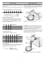
HB3x0W (sensor module)
HBLxW (lens module)
L7 lens may require pliers
to remove the lens. (Grab
one of the fins to remove.)
Tightening ring
Sensor Assembly
DIP switches
HB3x0W L2W/
HB3x0W L3W
HB3x0W L7W

2
Switch 1 2 PIR SENSITIVITY
OFF OFF High
ON OFF NORMAL
OFF ON Medium
ON ON Low
1 2 3 4 5 6 7 8 9 10
ON OFF OFF OFF OFF ON ON OFF N/A N/A
Switch 3 4 5 6 7 TIME DELAY
ON ON ON ON ON 15 seconds
OFF ON ON ON ON 5 minutes
OFF OFF ON ON ON 10 minutes
OFF OFF OFF ON ON 15 minutes
OFF OFF OFF OFF ON 20 minutes
OFF OFF OFF OFF OFF 30 minutes
PIR Sensitivity (Switches 1-2)
The factory setting (Normal) is suitable for most applications, but
it may be necessary to adjust the PIR sensitivity if there is any
environmental interference causing false triggers or if sensitivity
needs to be increased for your particular application. Use DIP
switches 1 & 2 to adjust sensitivity.
PIR Sensitivity (switches 1&2) .....................Normal
Time Delay (switches 3-7) .................... 15 minutes
Override (switch 8) ....Occupancy control enabled
Factory Switch Settings (N/A = not applicable, no effect)
Time Delay (Switches 3-7)
Use DIP switches 3 to 7 to adjust the time delay.
ADJUSTMENTS
The sensor is pre-set at the factory to meet the requirements of most
applications. Review this section if your application requires changing
factory pre-sets.
Sensor factory pre-sets are as follows (default settings are bold):
Override (Switch 8)
The override disables the occupancy control feature of the HB3x0W
sensor module. When occupancy control is disabled, the load
remains ON as long as the sensor is powered.
Switch 8 Load Effect
OFF Controlled by Occupancy
ON PIR override. Load always ON
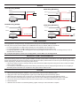
Wet location
light fixture
(supplied by others)
HB3xxW sensor
HBEM3W
Extender
housing
Chase nipple
Threaded nut
Rubber washer
Wet location
light fixture
(supplied by
others)
Threaded female
1
/
2
”
connector (supplied by others)
HB3x0W
sensor
MOUNTING OPTIONS
As shown in the illustration, the HB3x0W can be attached
directly to a watertight fixture or junction box that is equipped
with a threaded nipple. The center of the threaded nipple should
be no more than approximately one inch (1”) from the bottom of
the fixture to avoid blocking the sensor’s view.
The HBEM3W extender module allows attaching the sensor to
the side of the fixture so that the lens can be positioned below
the bottom edge of the fixture. The wiring cable is threaded
through it and into the fixture for connection. The two sides of
the HBEM3W snap together to protect the cable.
The extender housing is not watertight, but the inner flange rings
on the chase nipple and the HB3x0W housing fit into grooved
rubber rings on the the cable. This keeps moisture from entering
the fixture and sensor at those locations.
HB3x0W attached to a watertight light xture
HB3x0W attached to a watertight light xture using HBEM3W

3
LENS COVERAGE
Coverage patterns, density and range, are determined by the type of Lens attached to the HB3x0W.
Currently, there are three lenses available for the HB3x0W series sensors: HBL2W, HBL3W, and HBL7W.
• For low bay applications, the HBL2 pattern spreads over a 48’ diameter area at a height of 8’
• For mid bay applications, the HBL3 pattern spreads over a 40’ diameter area at a height of 20’.
• For high bay applications, the HBL7 is designed for mounting at heights between 20’ to 40’, with a coverage area up to 100’ in
diameter when mounted at 40’.
For a complete description of each lens coverage pattern, see the HBLx Lens Coverage Guide.
IMPORTANT START-UP INFORMATION
A 60-second start-up period occurs during initial installation and after a power failure of 5 minutes or more. After applying power to the
sensor wait at least 60 seconds for the sensor to begin detecting occupancy and the load to turn ON. It may turn ON during the start-up
period, depending on the state of the relay when power was off.
• If the sensor detects occupancy during the start-up, when the load turns ON it stays ON as long as the sensor continues to detect
motion, plus the Time Delay.
• If no occupancy is detected during the 60-second start-up, the load may come on anyway during the start-up. If no occupancy is
detected by the time the start-up is complete, the relay opens and the load turns OFF.
TESTING
1. When mounting and wiring are complete, cover up the sensor to prevent it from detecting motion.
2. Apply power to the sensor and light fixture. Lights may turn ON during the 60-second start-up period.
3. Wait for the start-up period to end. For the next 1 to 2 minutes the sensor runs through a self-diagnostic routine.
4. If the load came on during the start-up period, wait for it to turn OFF, indicating the self diagnostic routine is complete.
5. Uncover the sensor and confirm that when the sensor detects motion, it’s red LED blinks and the light turns ON.
6. Disconnect power.
7. Attach the lens as shown in the assembly drawing. Tighten securely to ensure that seal is complete.
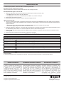
Neutral
Black Red
White
Line (Hot)
HB350W
Load
120/277VAC Wiring (HB350W)
Phase A
White
Red w/White Stripes
(Load B)
Phase B
HB340W-Lx
Load
480V
AC Wiring (HB-340W-Lx)
Black
Red
(Load A)
Line (Hot)
White
Red w/White Stripes
(Load B)
Neutral
HB340W-Lx
Load
347V
AC Wiring (HB-340W-Lx)
Black
Red
(Load A)
Cap
the
wire
Neutral
Phase A
White
Red w/White Stripes
(Load B)
Phase B
HB330W
Load
208/240VAC Wiring (HB330W)
Black
Red
(Load A)
WIRING

800.879.8585
www.legrand.us/wattstopper
No. 24140 – 8/17 rev. 2
© Copyright 2017 Legrand All Rights Reserved.
© Copyright 2017 Tous droits réservés Legrand.
© Copyright 2017 Legrand Todos los derechos reservados.
Wattstopper warranties its products to be free
of defects in materials and workmanship for a
period of five (5) years. There are no obligations
or liabilities on the part of Wattstopper for
consequential damages arising out of, or in
connection with, the use or performance of this
product or other indirect damages with respect
to loss of property, revenue or profit, or cost of
removal, installation or reinstallation.
Wattstopper garantit que ses produits sont
exempts de défauts de matériaux et de fabrication
pour une période de cinq (5) ans. Wattstopper
ne peut être tenu responsable de tout dommage
consécutif causé par ou lié à l’utilisation ou
à la performance de ce produit ou tout autre
dommage indirect lié à la perte de propriété, de
revenus, ou de profits, ou aux coûts d’enlèvement,
d’installation ou de réinstallation.
Wattstopper garantiza que sus productos
están libres de defectos en materiales y mano
de obra por un período de cinco (5) años. No
existen obligaciones ni responsabilidades por
parte de Wattstopper por daños consecuentes
que se deriven o estén relacionados con el
uso o el rendimiento de este producto u otros
daños indirectos con respecto a la pérdida
de propiedad, renta o ganancias, o al costo
de extracción, instalación o reinstalación.
WARRANTY INFORMATION INFORMATIONS RELATIVES À LA GARANTIE INFORMACIÓN DE LA GARANTÍA
TROUBLESHOOTING
To confirm proper operation, review the Start-Up and Testing information.
Red LED on sensor module does not blink:
Check for proper sensor wire connections and make sure they are tightly secured.
Red LED blinks but lights do not turn ON:
1. Make sure that power to the sensor has been ON continuously for at least one minute, then
a. Turn OFF power to the sensor. The relay will close.
b. Turn ON power to the sensor. The load should come ON. If not, continue with step 2.
2. Check power connections to the load.
3. Check all sensor wire connections. Verify the load wire is tightly secured.
Lights will not turn OFF:
1. If there is no motion from people or equipment in the sensor’s view but the red LED blinks, look for any nearby source of infrared
energy (heat) in motion, such as turbulent air from a heating or cooling supply, or other sources such as heat from the fluorescent
lamps in the fixture.
• Mount the sensor so that it’s lens is below the edge of the fixture and does not directly view the lamps.
• Divert the air supply away from the sensor, or move the sensor.
2. Verify time delay set in switches 3-7. The time delay can be set from 15 seconds to 30 minutes. Ensure that the time delay is set to
the desired delay and that there is no movement within the sensor’s view for that time period.
3. Check Override DIP switch setting. If switch 8 is ON, the PIR is overridden. Occupancy control functions are overridden and the
load stays ON.
4. Check sensor wire connections. Verify that all connections are complete.
ORDERING INFORMATION
Catalog # Description
A complete high bay line voltage occupancy sensor for wet locations consists of:
HB350W 120/277VAC IP65 Sensor module in watertight enclosure
HB340W 347/480VAC IP65 Sensor module in watertight enclosure
HB330W 208/240VAC IP65 Sensor module in watertight enclosure
HBL2W Wet location 360° lens, maximum coverage 48’ diameter at 8’ height
HBL3W Wet location 360° lens, maximum coverage 40’ diameter at 20’ height
HBL7W Wet location 360° lens, maximum coverage 100’ diameter at 40’ height
Optional mounting accessories
HBEM3W Extender module with 1 chase nipple, extender housing, rubber washer, two threaded nuts
All units are White.
To order preassembled custom configurations of sensors, lenses and mounting accessories, contact technical support.
-
 1
1
-
 2
2
-
 3
3
-
 4
4


dans d''autres langues
Documents connexes
Autres documents
-
Legrand HB350W-L3 High Bay Line Voltage Occupancy Sensor for Wet Locations Guide d'installation
-
-
-
-
-
-
Pass and Seymour PSHB120277WL3 Guide d'installation
-
-
-