Miller MG050034L Le manuel du propriétaire
- Catégorie
- Système de soudage
- Taper
- Le manuel du propriétaire
Ce manuel convient également à

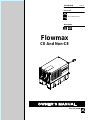
Flowmax
Processes
Description
TIG (GTAW) Welding
OM-248 626E 2015−12
File: TIG (GTAW)
CE And Non-CE
MIG (GMAW) Welding

TABLE OF CONTENTS
SECTION 1 − SAFETY PRECAUTIONS - READ BEFORE USING 1.................................
1-1. Symbol Usage 1.......................................................................
1-2. Cooling Equipment Hazards 1............................................................
1-3. Additional Symbols For Installation, Operation, And Maintenance 1.............................
1-4. California Proposition 65 Warnings 2......................................................
1-5. Principal Safety Standards 2.............................................................
SECTION 2 − CONSIGNES DE SÉCURITÉ − LIRE AVANT UTILISATION 3...........................
2-1. Symboles utilisés 3.....................................................................
2-2. Dangers liés aux équipements de refroidissement 3.........................................
2-3. Dangers supplémentaires en relation avec l’installation, le fonctionnement et la maintenance 3.....
2-4. Proposition californienne 65 Avertissements 4..............................................
2-5. Principales normes de sécurité 4.........................................................
SECTION 3 − DEFINITIONS 5..................................................................
3-1. Additional Safety Symbols And Definitions 5................................................
3-2. Miscellaneous Symbols And Definitions 6..................................................
SECTION 4 − SPECIFICATIONS 7..............................................................
4-1. Serial Number And Rating Label Location 7................................................
4-2. Specifications 7........................................................................
4-3. Coolant Chart 7........................................................................
4-4. Environmental Specifications 7...........................................................
SECTION 5 − INSTALLATION 8................................................................
5-1. GTAW Connections 8...................................................................
5-2. GMAW Connections 9..................................................................
SECTION 6 − MAINTENANCE & TROUBLESHOOTING 10.........................................
6-1. Routine Maintenance 10.................................................................
6-2. Coolant Maintenance 10.................................................................
6-3. Troubleshooting 10......................................................................
SECTION 7 − PARTS LIST 12...................................................................
WARRANTY

− 3 −
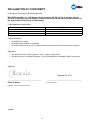
DECLARATION OF CONFORMITY
for European Community (CE marked) products.
MILLER Electric Mfg. Co., 1635 Spencer Street, Appleton, WI 54914 U.S.A. declares that the
product(s) identified in this declaration conform to the essential requirements and provisions of
the stated Council Directive(s) and Standard(s).
Product/Apparatus Identification:
Product
Stock Number
Flowmax 230 VAC 043008001
Council Directives:
• 2014/35/EU Low Voltage
• 2014/30/EU Electromagnetic Compatibility
• 2011/65/EU Restriction of the use of certain hazardous substances in electrical and electronic equipment
Standards:
• IEC 60974-2:2013 Arc welding equipment – Part 2: Liquid cooling systems
• IEC 60974-10:2007 Arc Welding Equipment – Part 10: Electromagnetic compatibility (EMC) requirements
Signatory:
_____________________________________ ___________________________________________
David A. Werba
Date of Declaration
MANAGER, PRODUCT DESIGN COMPLIANCE
December 02, 2015
245863D


OM-248 626 Page 1
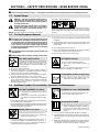
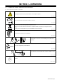
SECTION 1 − SAFETY PRECAUTIONS - READ BEFORE USING
coolers 2015-09
7
Protect yourself and others from injury — read, follow, and save these important safety precautions and operating instructions.
1-1. Symbol Usage
DANGER! − Indicates a hazardous situation which, if
not avoided, will result in death or serious injury. The
possible hazards are shown in the adjoining symbols
or explained in the text.
Indicates a hazardous situation which, if not avoided,
could result in death or serious injury. The possible
hazards are shown in the adjoining symbols or ex-
plained in the text.
NOTICE − Indicates statements not related to personal injury.
. Indicates special instructions.
This group of symbols means Warning! Watch Out! ELECTRIC
SHOCK, MOVING PARTS, and HOT PARTS hazards. Consult sym-
bols and related instructions below for necessary actions to avoid the
hazards.
1-2. Cooling Equipment Hazards
The symbols shown below are used throughout this manual
to call attention to and identify possible hazards. When you
see the symbol, watch out, and follow the related instructions
to avoid the hazard. The safety information given below is
only a summary of the more complete safety information
found in the Safety Standards listed in Section 1-5. Read and
follow all Safety Standards.
Only qualified persons should install, operate, maintain, and
repair this unit.
During operation, keep everybody, especially children, away.
Touching live electrical parts can cause fatal shock
s
or severe burns. The input power circuit and machine
internal circuits are also live when power is on
.
Incorrectly installed or improperly grounded equip
-
ment is a hazard.
ELECTRIC SHOCK can kill.
D Do not touch live electrical parts.
D Disconnect input power or stop engine before installing or
servicing this equipment. Lockout/tagout input power according to
OSHA 29 CFR 1910.147 (see Safety Standards).
D Properly install, ground, and operate this equipment according to
its Owner’s Manual and national, state, and local codes.
D Always verify the supply ground − check and be sure that input
power cord ground wire is properly connected to ground terminal in
disconnect box or that cord plug is connected to a properly
grounded receptacle outlet.
D Keep cords dry, free of oil and grease, and protected from hot metal
and sparks.
D Frequently inspect input power cord and ground conductor for
damage or bare wiring – replace immediately if damaged – bare
wiring can kill.
D Turn off all equipment when not in use.
D Use only well-maintained equipment. Repair or replace damaged
parts at once. Maintain unit according to manual.
D Keep all panels and covers securely in place.
HOT PARTS can burn.
D Do not touch hot parts bare handed.
D Allow cooling period before working on
equipment.
D To handle hot parts, use proper tools and/or wear heavy, insu-
lated welding gloves and clothing to prevent burns.
FLYING METAL or DIRT can injure eyes.
D Wear approved safety glasses with side
shields even under your welding helmet.
1-3. Additional Symbols For Installation, Operation, And Maintenance
FALLING EQUIPMENT can injure.
D Use equipment of adequate capacity to lift and
support unit.
D If using lift forks to move unit, be sure forks are
long enough to extend beyond opposite side of
unit.
D Keep equipment (cables and cords) away from moving vehicles
when working from an aerial location.
D Follow the guidelines in the Applications Manual for the Revised
NIOSH Lifting Equation (Publication No. 94−110) when manu-
ally lifting heavy parts or equipment.
MOVING PARTS can injure.
D Keep away from moving parts such as fans.
D Keep all doors, panels, covers, and guards
closed and securely in place.
D Have only qualified persons remove doors, panels, covers, or
guards for maintenance and troubleshooting as necessary.
D Reinstall doors, panels, covers, or guards when maintenance is
finished and before reconnecting input power.
OVERUSE can cause OVERHEATING
D Allow cooling period; follow rated duty cycle.
D Do not block or filter airflow to unit.
READ INSTRUCTIONS.
D Read and follow all labels and the Owner’s
Manual carefully before installing, operating, or
servicing unit. Read the safety information at
the beginning of the manual and in each
section.
D Use only genuine replacement parts from the manufacturer.
D Perform installation, maintenance, and service according to the
Owner’s Manuals, industry standards, and national, state, and
local codes.
D Read and understand the Safety Data Sheets (SDSs) and the
manufacturer’s instructions for adhesives, coatings, cleaners,
consumables, coolants, degreasers, fluxes, and metals.

OM-248 626 Page 2
1-4. California Proposition 65 Warnings
Welding or cutting equipment produces fumes or gases
which contain chemicals known to the State of California to
cause birth defects and, in some cases, cancer. (California
Health & Safety Code Section 25249.5 et seq.)
This product contains or produces a chemical known to the
state of California to cause cancer or birth defects (or other
reproductive harm). (California Health & Safety Code Section
25249.5 et seq.)
This product contains chemicals, including lead, known to
the state of California to cause cancer, birth defects, or other
reproductive harm. Wash hands after use.
1-5. Principal Safety Standards
Safety in Welding, Cutting, and Allied Processes, ANSI Standard Z49.1,
is available as a free download from the American Welding Society at
http://www.aws.org or purchased from Global Engineering Documents
(phone: 1-877-413-5184, website: www.global.ihs.com).
Safe Practices for the Preparation of Containers and Piping for Welding
and Cutting, American Welding Society Standard AWS F4.1, from Glob-
al Engineering Documents (phone: 1-877-413-5184, website:
www.global.ihs.com).
Safe Practices for Welding and Cutting Containers that have Held Com-
bustibles, American Welding Society Standard AWS A6.0, from Global
Engineering Documents (phone: 1-877-413-5184,
website: www.global.ihs.com).
National Electrical Code, NFPA Standard 70, from National Fire Protec-
tion Association, Quincy, MA 02269 (phone: 1-800-344-3555, website:
www.nfpa.org and www. sparky.org).
Safe Handling of Compressed Gases in Cylinders, CGA Pamphlet P-1,
from Compressed Gas Association, 14501 George Carter Way, Suite
103, Chantilly, VA 20151 (phone: 703-788-2700, website:
www.cganet.com).
Safety in Welding, Cutting, and Allied Processes, CSA Standard
W117.2, from Canadian Standards Association, Standards Sales, 5060
Spectrum Way, Suite 100, Mississauga, Ontario, Canada L4W 5NS
(phone: 800-463-6727, website: www.csagroup.org).
Safe Practice For Occupational And Educational Eye And Face Protec-
tion, ANSI Standard Z87.1, from American National Standards Institute,
25 West 43rd Street, New York, NY 10036 (phone: 212-642-4900, web-
site: www.ansi.org).
Standard for Fire Prevention During Welding, Cutting, and Other Hot
Work, NFPA Standard 51B, from National Fire Protection Association,
Quincy, MA 02269 (phone: 1-800-344-3555, website: www.nfpa.org).
OSHA, Occupational Safety and Health Standards for General Indus-
try, Title 29, Code of Federal Regulations (CFR), Part 1910, Subpart Q,
and Part 1926, Subpart J, from U.S. Government Printing Office, Super-
intendent of Documents, P.O. Box 371954, Pittsburgh, PA 15250-7954
(phone: 1-866-512-1800) (there are 10 OSHA Regional Offices—
phone for Region 5, Chicago, is 312-353-2220, website:
www.osha.gov).
Applications Manual for the Revised NIOSH Lifting Equation, The Na-
tional Institute for Occupational Safety and Health (NIOSH), 1600
Clifton Rd, Atlanta, GA 30329-4027 (phone: 1-800-232-4636, website:
www.cdc.gov/NIOSH).

OM-248 626 Page 3
SECTION 2 − CONSIGNES DE SÉCURITÉ − LIRE AVANT UTILISATION
Cooler 2015−09_fre
Pour écarter les risques de blessure pour vous−même et pour autrui — lire, appliquer et ranger en lieu sûr ces consignes relatives
aux précautions de sécurité et au mode opératoire.
2-1. Symboles utilisés
DANGER! − Indique une situation dangereuse qui si on
l’évite pas peut donner la mort ou des blessures graves.
Les dangers possibles sont montrés par les symboles
joints ou sont expliqués dans le texte.
Indique une situation dangereuse qui si on l’évite pas
peut donner la mort ou des blessures graves. Les
dangers possibles sont montrés par les symboles
joints ou sont expliqués dans le texte.
AVIS − Indique des déclarations pas en relation avec des blessures
personnelles.
. Indique des instructions spécifiques.
Ce groupe de symboles veut dire Avertissement! Attention! DANGER
DE CHOC ELECTRIQUE, PIECES EN MOUVEMENT, et PIECES
CHAUDES. Consulter les symboles et les instructions ci-dessous y
afférant pour les actions nécessaires afin d’éviter le danger.
2-2. Dangers liés aux équipements de refroidissement
Les symboles représentés ci-dessous sont utilisés dans ce
manuel pour attirer l’attention et identifier les dangers possibles.
En présence de l’un de ces symboles, prendre garde et suivre
les instructions afférentes pour éviter tout risque. Les
instructions en matière de sécurité indiquées ci-dessous ne
constituent qu’un sommaire des instructions de sécurité plus
complètes fournies dans les normes de sécurité énumérées
dans la Section 2-5. Lire et observer toutes les normes de
sécurité.
Seul un personnel qualifié est autorisé à installer, faire
fonctionner, entretenir et réparer cet appareil.
Pendant le fonctionnement, maintenir à distance toutes les
personnes, notamment les enfants de l’appareil.
Le contact d’organes électriques sous tension peut
provoquer des accidents mortels ou des brûlures
graves. Le circuit d’alimentation et les circuits
internes de la machine sont également sous tension
lorsque l’alimentation est sur Marche. Un équipement installé ou mis
à la terre de manière incorrecte ou impropre constitue un danger.
UNE DÉCHARGE ÉLECTRIQUE peut
entraîner la mort.
D Ne pas toucher aux pièces électriques sous tension.
D Couper l’alimentation ou arrêter le moteur avant de procéder
à l’installation, à la réparation ou à l’entretien de l’appareil.
Déverrouiller l’alimentation selon la norme OSHA 29 CFR
1910.147 (voir normes de sécurité).
D Installez, mettez à la terre et utilisez correctement cet équipement
conformément à son Manuel d’Utilisation et aux réglementations
nationales, gouvernementales et locales.
D Toujours vérifier la terre du cordon d’alimentation. Vérifier et
s’assurer que le fil de terre du cordon d’alimentation est bien
raccordé à la borne de terre du sectionneur ou que la fiche du
cordon est raccordée à une prise correctement mise à la terre.
D Les câbles doivent être exempts d’humidité, d’huile et de graisse;
protégez−les contre les étincelles et les pièces métalliques
chaudes.
D Vérifier fréquemment le cordon d’alimentation afin de s’assurer
qu’il n’est pas altéré ou à nu, le remplacer immédiatement s’il l’est.
Un fil à nu peut entraîner la mort.
D L’équipement doit être hors tension lorsqu’il n’est pas utilisé.
D N’utiliser qu’un matériel en bon état. Réparer ou remplacer
sur-le-champ les pièces endommagées. Entretenir l’appareil
conformément à ce manuel.
D S’assurer que tous les panneaux et couvercles sont correctement
en place.
LES PIÈCES CHAUDES peuvent
provoquer des brûlures.
D Ne pas toucher à mains nues les parti
es
chaudes.
D Prévoir une période de refroidissement avant
de
travailler à l’équipement.
D Ne pas toucher aux pièces chaudes, utiliser les outils recomma
n-
dés et porter des gants de soudage et des vêtements épais po
ur
éviter les brûlures.
DES PIECES DE METAL ou DES
SALETES peuvent provoquer des
blessures dans les yeux.
D Porter des lunettes de sécurité avec écrans
latéraux ou un écran facial.
2-3. Dangers supplémentaires en relation avec l’installation, le fonctionnement et la maintenanc
e
LA CHUTE DE L’ÉQUIPEMENT peut
provoquer des blessures.
D Utiliser un équipement de levage de capacité
suffisante pour lever l’appareil.
D En utilisant des fourches de levage pour
déplacer l’unité, s’assurer que les fourches
sont suffisamment longues pour dépasser du
côté opposé de l’appareil.
D Tenir l’équipement (câbles et cordons) à distance des véhicules
mobiles lors de toute opération en hauteur.
D Suivre les consignes du Manuel des applications pour l’équation
de levage NIOSH révisée (Publication Nº94–110) lors du levage
manuelle de pièces ou équipements lourds.
L’EMPLOI EXCESSIF peut
SURCHAUFFER L’ÉQUIPEMENT.
D Prévoir une période de refroidissement ;
respecter le cycle opératoire nominal.
D Ne pas obstruer les passages d’air du poste.

OM-248 626 Page 4
Les PIÈCES MOBILES peuvent
causer des blessures.
D S’abstenir de toucher des organes mobiles tels
que des ventilateurs.
D Maintenir fermés et verrouillés les portes,
panneaux, recouvrements et dispositifs de
protection.
D Lorsque cela est nécessaire pour des travaux d’entretien et de
dépannage, faire retirer les portes, panneaux, recouvrements
ou dispositifs de protection uniquement par du personnel
qualifié.
D Remettre les portes, panneaux, recouvrements ou dispositifs de
protection quand l’entretien est terminé et avant de rebrancher
l’alimentation électrique.
LIRE LES INSTRUCTIONS.
D Lire et appliquer les instructions sur les
étiquettes et le Mode d’emploi avant
l’installation, l’utilisation ou l’entretien de
l’appareil. Lire les informations de sécurité au
début du manuel et dans chaque section.
D N’utiliser que les pièces de rechange recommandées par le
constructeur.
D Effectuer l’installation, l’entretien et toute intervention selon les
manuels d’utilisateurs, les normes nationales, provinciales et de
l’industrie, ainsi que les codes municipaux.
D Lire et comprendre les fiches de données de sécurité et les
instructions du fabricant concernant les adhésifs, les revêtements,
les nettoyants, les consommables, les produits de refroidissement,
les dégraisseurs, les flux et les métaux.
2-4. Proposition californienne 65 Avertissements
Les équipements de soudage et de coupage produisent des
fumées et des gaz qui contiennent des produits chimiques
dont l’État de Californie reconnaît qu’ils provoquent des
malformations congénitales et, dans certains cas, des
cancers. (Code de santé et de sécurité de Californie, chapitre
25249.5 et suivants)
Ce produit contient ou forme un produit chimique reconnu
par l’état de Californie de provoquer le cancer ou
malformations de naissance (ou autre problèmes
reproductifs. (Code de santé et de sécurité de Californie,
chapitre 25249.5 et suivants).
Ce produit contient des produits chimiques, notamment du
plomb, dont l’État de Californie reconnaît qu’ils provoquent
des cancers, des malformations congénitales ou d’autres
problèmes de procréation. Se laver les mains après
utilisation.
2-5. Principales normes de sécurité
Safety in Welding, Cutting, and Allied Processes, ANSI Standard Z49.1,
is available as a free download from the American Welding Society at
http://www.aws.org or purchased from Global Engineering Documents
(phone: 1-877-413-5184, website: www.global.ihs.com).
Safe Practices for the Preparation of Containers and Piping for Welding
and Cutting, American Welding Society Standard AWS F4.1, from
Global Engineering Documents (phone: 1-877-413-5184, website:
www.global.ihs.com).
Safe Practices for Welding and Cutting Containers that have Held
Combustibles, American Welding Society Standard AWS A6.0, from
Global Engineering Documents (phone: 1-877-413-5184,
website: www.global.ihs.com).
National Electrical Code, NFPA Standard 70, from National Fire
Protection Association, Quincy, MA 02269 (phone: 1-800-344-3555,
website: www.nfpa.org and www. sparky.org).
Safe Handling of Compressed Gases in Cylinders, CGA Pamphlet P-1,
from Compressed Gas Association, 14501 George Carter Way, Suite
103, Chantilly, VA 20151 (phone: 703-788-2700, website:
www.cganet.com).
Safety in Welding, Cutting, and Allied Processes, CSA Standard
W117.2, from Canadian Standards Association, Standards Sales, 5060
Spectrum Way, Suite 100, Mississauga, Ontario, Canada L4W 5NS
(phone: 800-463-6727, website: www.csagroup.org).
Safe Practice For Occupational And Educational Eye And Face
Protection, ANSI Standard Z87.1, from American National Standards
Institute, 25 West 43rd Street, New York, NY 10036 (phone:
212-642-4900, website: www.ansi.org).
Standard for Fire Prevention During Welding, Cutting, and Other Hot
Work, NFPA Standard 51B, from National Fire Protection Association,
Quincy, MA 02269 (phone: 1-800-344-3555, website: www.nfpa.org).
OSHA, Occupational Safety and Health Standards for General
Industry, Title 29, Code of Federal Regulations (CFR), Part 1910,
Subpart Q, and Part 1926, Subpart J, from U.S. Government Printing
Office, Superintendent of Documents, P.O. Box 371954, Pittsburgh, PA
15250-7954 (phone: 1-866-512-1800) (there are 10 OSHA Regional
Offices—phone for Region 5, Chicago, is 312-353-2220, website:
www.osha.gov).
Applications Manual for the Revised NIOSH Lifting Equation, The
National Institute for Occupational Safety and Health (NIOSH), 1600
Clifton Rd, Atlanta, GA 30329-4027 (phone: 1-800-232-4636, website:
www.cdc.gov/NIOSH).

OM-248 626 Page 5
SECTION 3 − DEFINITIONS
3-1. Additional Safety Symbols And Definitions
. Some symbols are found only on CE products.
Warning! Watch Out! There are possible hazards as shown by the symbols.
Safe1 2012−05
Disconnect input plug or power before working on machine.
Safe5 2012−05
Do not discard product (where applicable) with general waste.
Reuse or recycle Waste Electrical and Electronic Equipment (WEEE) by disposing at a designated collection
facility.
Contact your local recycling office or your local distributor for further information.
Safe37 2012−05
Do not remove or paint over (cover) the label.
Safe20 2012−05
Safe50 2012−05
Plugged filter or hoses can cause overheating to the power source
and torch.
XXXXX
Use coolant suggested by the manufacturer.
Safe52 2012−05
100 h. Std.
Safe51 2012−05
Every 100 hours, check and clean filter and check condition of hoses.
Recycle.
Safe103 2012−09

OM-248 626 Page 6
3-2. Miscellaneous Symbols And Definitions
A
Amperes Alternating Current Voltage Input
Circulating Unit
With Coolant Pump
V
Volts
Water (Coolant)
Input
Water (Coolant)
Output
Line Connection
Protective Earth
(Ground)
IP
Degree Of
Protection
I
1
Primary Current
Hz
Hertz
On Off
U
1
Primary Voltage Single Phase
Notes

OM-248 626 Page 7
SECTION 4 − SPECIFICATIONS
4-1. Serial Number And Rating Label Location
The serial number and rating information for this product is located on the back panel. Use rating label to determine input power requirements and/or
rated output. For future reference, write serial number in space provided on cover of this manual.
4-2. Specifications
801 189-D
Recirculating Coolant System For Water-Cooled GTAW Torches, GMAW Guns, And Induction Heaters
Use With Guns/Torches Rated Up To 600 Amperes
3 gal (11.4 L) Coolant Tank Capacity;
Maximum Cooling Capacity: 14,000 BTU/hr At 1.25 qt/min (1.2 L/min)
Dimensions: 23 in. (584 mm) Long, 12 in. (305 mm) Wide, 13-1/4 in. (337 mm) High
Weight: 39 lb (18 kg)
115 Volt Model Use 5.9 Amperes, 50/60 Hertz, Single-Phase Input Power
230 Volt CE Model Use 3 Amperes, 50/60 Hertz, Single-Phase Input Power
Ratings Developed At An Ambient Temperature Of 68°F to 77° F (20° C To 25° C)
4-3. Coolant Chart
Low Conductivity Coolant
No. 043 810**;
Distilled Or Deionized Water
OK Above 32° F (0° C)
Low Conductivity Coolant
No. 043 810**; Or
Aluminum Protecting Coolant
No. 043 809**;
Distilled Or Deionized Water
OK Above 32° F (0° C)
GTAW Or Where
HF* Is Used
GMAW Or Where
HF* Is Not Used
Application
*HF: High Frequency Current
**Coolants 043 810 and 043 809 protect to -37° F (-38°C) and resist algae growth.
Coolant
Aluminum Protecting
Coolant No. 043 809**
Where Coolant Contacts
Aluminum Parts
NOTICE − Use of any coolant other than those listed in the table voids the warranty on any parts
that come in contact with the coolant (pump, radiator, etc.).
4-4. Environmental Specifications
A. IP Rating
IP Rating Operating Temperature Range
IP23
This equipment is designed for outdoor use. It
may be stored, but is not intended to be used
for welding outside during precipitation unless
sheltered.
14 to 104 °F (-10 to 40°C)
IP23 2014−06
B. Information On Electromagnetic Fields (EMF)
! This equipment shall not be used by the general public as the EMF limits for the general public might be exceeded during welding.
This equipment is built in accordance with EN 60974−1 and is intended to be used only in an occupational environment (where the general public
access is prohibited or regulated in such a way as to be similar to occupational use) by an expert or an instructed person.
Wire feeders and ancillary equipment (such as torches, liquid cooling systems and arc striking and stabilizing devices) as part of the welding
circuit may not be a major contributor to the EMF. See the Owner’s Manuals for all components of the welding circuit for additional EMF exposure
information.
S The EMF assessment on this equipment was conducted at 0.5 meter.
S At a distance of 1 meter the EMF exposure values were less than 20% of the permissible values.
ce-emf 1 2010-10

OM-248 626 Page 8
C. Information On Electromagnetic Compatibility (EMC)
! This Class A equipment is not intended for use in residential locations where the electrical power is provided by the public low−
voltage supply system. There can be potential difficulties in ensuring electromagnetic compatibility in those locations, due to con-
ducted as well as radiated disturbances.
This equipment complies with IEC 61000-3-11 and IEC 61000-3-12.
ce-emc 4 2014-07
Notes

OM-248 626 Page 9
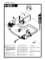
SECTION 5 − INSTALLATION
5-1. GTAW Connections
801 190-E
! Do not move or operate unit where
it could tip.
! 230 volt AC coolers only: Replace
power cord plug if supplied plug
does not match receptacle. Have a
qualified person install correct 230
volt AC plug according to national
and local codes.
1 Lift -Eye
If placing cooling unit on welding power
source, slots are provided in bottom of unit
so it fits over lift-eye.
To prevent overheating, make sure cooling
unit is positioned so airflow is not restricted.
2 115 Or 230 Volt AC Grounded Re-
ceptacle (Depending On Model)
An individual circuit capable of carrying 15
amperes and protected by fuses or circuit
breakers is recommended. Recom-
mended fuse or circuit breaker size is 15
amperes. For 230 volt models, an individu-
al branch circuit capable of carrying 10 am-
peres and protected by fuses or circuit
breakers is recommended. Recom-
mended fuse or circuit breaker size is 10
amperes.
NOTICE − If welding power source has a
water valve, do not connect hoses to water
valve. Connect hoses as shown.
3 Coolant Out Hose
4 Coolant In Hose
Fittings have 5/8-18 left-hand threads.
Connect hoses with proper fittings as
shown.
5 TIG Block
Customer supplied for use with some weld-
ing power sources, or use proper connec-
tor supplied with welding power source.
6 Coolant Tank Cap
Use table in Section 4-3 to select proper
coolant, and fill tank. Maintain coolant level
at approximately 1 in. (25 mm) below top of
filler neck.
7 Power Switch
Operation:
Turn power switch On.
1
Tools Needed:
5/8 in.
3
4
6
7
5
2

OM-248 626 Page 10
5-2. GMAW Connections
801 191-E
Tools Needed:
5/8 in.
! Do not move or operate unit where
it could tip.
! 230 volt AC coolers only: Replace
power cord plug if supplied plug
does not match receptacle. Have a
qualified person install correct 230
volt AC plug according to national
and local codes.
1 Lift -Eye
If placing cooling unit on welding power
source, slots are provided in bottom of unit
so it fits over lift-eye.
To prevent overheating, make sure cooling
unit is positioned so airflow is not restricted.
2 115 Or 230 Volt AC Grounded Re-
ceptacle (Depending On Model)
An individual circuit capable of carrying 15
amperes and protected by fuses or circuit
breakers is recommended. Recom-
mended fuse or circuit breaker size is 15
amperes. For 230 volt models, an individu-
al branch circuit capable of carrying 10 am-
peres and protected by fuses or circuit
breakers is recommended. Recom-
mended fuse or circuit breaker size is 10
amperes.
NOTICE − If welding power source has a
water valve, do not connect hoses to water
valve. Connect hoses as shown.
3 Coolant Out Hose
4 Coolant In Hose
Fittings have 5/8-18 left-hand threads.
Connect hoses with proper fittings as
shown.
5 Coolant Tank Cap
Use table in Section 4-3 to select proper
coolant, and fill tank. Maintain coolant level
at approximately 1 in. (25 mm) below top of
filler neck.
6 Power Switch
Operation:
Turn power switch On.
3
4
5
6
1
2

OM-248 626 Page 11
SECTION 6 − MAINTENANCE & TROUBLESHOOTING
6-1. Routine Maintenance
! Disconnect power
before maintaining.
n = Check Z = Change ~ = Clean Δ = Repair l = Replace
* To be done by Factory Authorized Service Agent
Every
3
Months
~Coolant Filter, durning heavy
service, clean more frequently.
~ Blow out heat exchanger fins.
nCheck coolant level. Top off with
distilled or deionized water if necessary.
Every
6
Months
nlHoses
nl Labels
ZReplace coolant.
Change
Coolant (If
Using Water)
Every
12
Months
ZReplace coolant.
Change
Coolant (If
Using 043 809
or 043 810
Coolant)
3/8 in.
Tools Needed:
6-2. Coolant Maintenance
801 189-D / 803 557-A
1 Coolant Filter
Unscrew housing to clean filter.
Changing coolant: Drain coolant by
tipping unit forward. Fill with clean
water and run for 10 minutes. Drain
and refill.
. If replacing hoses, use hoses
compatible with ethylene gly-
col, such as Buna-n, Neo-
prene, or Hypalon. Oxy-acety-
lene hoses are not compatible
with any product containing
ethylene glycol.
1
6-3. Troubleshooting
Trouble Remedy
Coolant system does not work. Be sure input power cord is plugged in to energized receptacle.
Check line fuses or circuit breaker, and replace or reset if necessary.
Motor overheated. Unit starts running when motor has cooled.
Have Factory Authorized Service Agent check Power switch S1 and motor (Mot).
Decreased or no coolant flow. Add coolant.
Check for clogged hoses or coolant filter. Clean filter or clean / replace hoses if necessary.
Disconnect pump, and check for sheared coupling. Replace coupling if necessary.

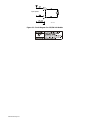
OM-248 626 Page 12
135 796-D
Figure 6-1. Circuit Diagram For 115/230 Volt Models
Input power

OM-248 626 Page 13
Notes

OM-248 626 Page 14
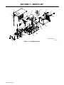
SECTION 7 − PARTS LIST
805 487-D
*included with item 25
1
2
4
5
6
7
8
9
10
11
12
13
14
15
16
17
12
18
12
21
20
21
22
24
23
12
22
26
25
29
27
28
30
31
23
*
Figure 7-1. Complete Assembly

OM-248 626 Page 15
Description
Part
No.
Dia.
Mkgs.
Item
No.
Figure 7-1. Complete Assembly
Quantit
y
Flowmax-115
Flowmax-230 CE
1 +166 562 Wrapper 1.... .......... ..... .......................................................
2 253 514 Label, Warning General Precautionary Static (Eng/Fr) 1... ........... ..... ...............
4 255 480 Pump Coolant W/Fittings, (Includes) 1... ........... ..... ...............................
5 5523 Fitting, Hose Brs Barbed M 3/8tbg X 3/8 NPT 2... .............. ....... .....................
6 134 795 Coupler, Drive Pump 1... ........... ....... ...........................................
7 196 990 Fitting, Hose Brs Barbed 1... ........... ..... .......................................
8 149 332 Clamp, Hose .405 − .485 Clip 1... ........... ..... .....................................
9 196 991 Hose, Nprn Brd No 1 X .250ID 1... ........... ..... ....................................
10 MOT 173 264 Motor, 1/4hp 230VAC 50/60HZ 1425/1725RPM (230V CE Model) 1... ... .. ..... .....
10 MOT 173 263 Motor, 1/4hp 115VAC 50/60hz 1425/1725RPM (115V Model) 1... ... .. ..... ..........
11 166 570 Blade, Fan 9.000 5wg 38deg .500 Bore CW (Setscrew Included) 1... ........... ..... ......
12 231 400 Hose, Rubber Braided .375 ID X .650 OD X 17.000 2... ........... ..... ..................
13 094 263 Clamp, 1-Ear Type Nom Dim .718 X .276 Wide 8... ........... ..... .....................
14 192 454 Panel, Rear 1... ........... ..... ....................................................
15 139 042 Bushing, Strain Relief .270/.480 ID X .804 Mtg Hol 1... ........... ..... ..................
16 PLG1 192 457 Cable, Power 10ft 16ga (115V Model) 1... .. .. ..... ..............................
16 PLG1 192 458 Cable, Pwr 11ft (230V CE Model) 1... .. .. ..... .................................
17 196 515 Radiator, Heat Exchanger 1... ........... ..... ........................................
18 269 910 Tank Coolant 1... ........... ..... ...................................................
20 166 608 Cap, Tank Screw-On W/Vent 1... ........... ..... .....................................
21 255 481 Hose, Pick-up Coolant W/Clamp 1... ........... ..... ..................................
22 236 084 Hose, Rubber Braided .375 ID X .650 OD X 10.500 1... ........... ..... ..................
23 255 485 Hose, Rubber Braided .375 ID X .650 OD X 3.750 1... ........... ..... ...................
24 166 560 Ring, Ring Ext .500 Shaft Grv X .042thk 2... ........... ..... ............................
25 166 564 Filter, In-Line 1... ........... ..... ...................................................
27 S1 177 396 Switch, Rocker DPST 15A 250VAC 1... .... ... ..... ................................
28 177 399 Panel, Front 1... ........... ..... ....................................................
29 GB0002 Plug, Knock-Out 1-11/16 1... ........... ..... .........................................
30 Nameplate, (Order By Model And Serial Number) 1... ......................... ...................
31 166 571 Fitting, Coolant Barbed 3/8tbg 5/8-18 Female 2... ........... ..... .......................
+When ordering a component originally displaying a precautionary label, the label should also be ordered.
BE SURE TO PROVIDE MODEL AND SERIAL NUMBER WHEN ORDERING REPLACEMENT PARTS.

TM-222 Page 16 Gold Star Series
Notes
La page est en cours de chargement...
La page est en cours de chargement...
La page est en cours de chargement...
La page est en cours de chargement...
-
 1
1
-
 2
2
-
 3
3
-
 4
4
-
 5
5
-
 6
6
-
 7
7
-
 8
8
-
 9
9
-
 10
10
-
 11
11
-
 12
12
-
 13
13
-
 14
14
-
 15
15
-
 16
16
-
 17
17
-
 18
18
-
 19
19
-
 20
20
-
 21
21
-
 22
22
-
 23
23
-
 24
24


Miller MG050034L Le manuel du propriétaire
- Catégorie
- Système de soudage
- Taper
- Le manuel du propriétaire
- Ce manuel convient également à
dans d''autres langues
- English: Miller MG050034L Owner's manual
Documents connexes
-
Miller FLOWMAX Le manuel du propriétaire
-
-
Miller Coolmate V3 Le manuel du propriétaire
-
-
-
-
Miller Coolmate 1 Le manuel du propriétaire
-
Miller MC170519J Le manuel du propriétaire
-
Miller Coolmate 3 Le manuel du propriétaire
-