Jenn-Air JXL6536CSS Guide d'installation
- Catégorie
- Hottes
- Taper
- Guide d'installation

36" (91.4 CM) HOOD LINER
CAISSE DE HOTTE
36" (91,4 CM)
Installation Instructions and Use & Care Guide
For questions about features, operation/performance, parts, accessories, or service in the U.S.A., call:
1-800-JENNAIR (1-800-536-6247), or visit our website at www.jennair.com.
In Canada, call: 1-800-JENNAIR (1-800-536-6247), or visit our website at www.jennair.ca.
Instructions d’installation et Guide d’utilisation et d’entretien
Au Canada, pour assistance, installation ou service, composez le 1-800-JENNAIR (1-800-536-6247) ou visitez notre site web à
www.jennair.ca.
Table of Contents/Table des matières................... 2
IMPORTANT: READ AND SAVE THESE INSTRUCTIONS.
FOR RESIDENTIAL USE ONLY.
IMPORTANT : LIRE ET CONSERVER CES INSTRUCTIONS.
POUR UTILISATION RÉSIDENTIELLE UNIQUEMENT.
LI310A/W10635570A

2
TABLE OF CONTENTS
RANGE HOOD SAFETY .................................................................2
INSTALLATION REQUIREMENTS................................................4
Tools and Parts ............................................................................4
Location Requirements................................................................4
Venting Requirements..................................................................5
Electrical Requirements ...............................................................6
INSTALLATION INSTRUCTIONS..................................................7
Prepare Location..........................................................................7
Install Hood Liner Internal Blower Motor .....................................8
Install Hood Liner In-Line (External Type) Blower Motor...........10
Make Electrical Connections for In-Line Blower Motor System ...
11
Make Electrical Power Supply Connection to Hood Liner........12
Complete Installation and Check Operation..............................13
RANGE HOOD USE......................................................................14
Range Hood Controls ................................................................14
RANGE HOOD CARE...................................................................15
Cleaning......................................................................................15
WIRING DIAGRAM .......................................................................16
ASSISTANCE OR SERVICE.........................................................17
In the U.S.A. ...............................................................................17
In Canada ...................................................................................17
Accessories................................................................................17
WARRANTY ..................................................................................18
TABLE DES MATIÈRES
SÉCURITÉ DE LA HOTTE DE CUISINIÈRE................................20
EXIGENCES D'INSTALLATION...................................................22
Outils et pièces...........................................................................22
Exigences d'emplacement.........................................................22
Exigences concernant l’évacuation ...........................................23
Spécifications électriques ..........................................................24
INSTRUCTIONS D’INSTALLATION.............................................25
Préparation de l'emplacement...................................................25
Installation du moteur du ventilateur interne de
la caisse de la hotte....................................................................26
Installation du moteur du ventilateur en ligne (externe)
de la caisse de la hotte ..............................................................28
Réalisation des connexions électriques du système du moteur du
ventilateur en ligne .....................................................................29
Réalisation des connexions de l’alimentation électrique à
la caisse de la hotte....................................................................31
Achever l'installation et vérifier le fonctionnement ....................31
UTILISATION DE LA HOTTE .......................................................32
Commandes de la hotte de cuisinière .......................................32
ENTRETIEN DE LA HOTTE..........................................................33
Nettoyage ...................................................................................33
SCHÉMA DE CÂBLAGE...............................................................34
ASSISTANCE OU SERVICE.........................................................35
Au Canada..................................................................................35
Accessoires ................................................................................35
GARANTIE.....................................................................................35
RANGE HOOD SAFETY
You can be killed or seriously injured if you don't immediately
You
can be killed or seriously injured if you don't
follow
All safety messages will tell you what the potential hazard is, tell you how to reduce the chance of injury, and tell you what can
happen if the instructions are not followed.
Your safety and the safety of others are very important.
We have provided many important safety messages in this manual and on your appliance. Always read and obey all safety
messages.
This is the safety alert symbol.
This symbol alerts you to potential hazards that can kill or hurt you and others.
All safety messages will follow the safety alert symbol and either the word “DANGER” or “WARNING.”
These words mean:
follow instructions.
instructions.
DANGER
WARNING
State of California Proposition 65 Warnings:
WARNING: This product contains one or more chemicals known to the State of California to cause cancer.
WARNING: This product contains one or more chemicals known to the State of California to cause birth defects or other
reproductive harm.

3
IMPORTANT SAFETY INSTRUCTIONS
READ AND SAVE THESE INSTRUCTIONS
WARNING: TO REDUCE THE RISK OF FIRE, ELECTRIC
SHOCK, OR INJURY TO PERSONS, OBSERVE THE
FOLLOWING:
■ Use this unit only in the manner intended by the
manufacturer. If you have questions, contact the
manufacturer.
■ Before servicing or cleaning the unit, switch power off at
service panel and lock the service disconnecting means to
prevent power from being switched on accidentally. When
the service disconnecting means cannot be locked,
securely fasten a prominent warning device, such as a tag,
to the service panel.
■ Installation work and electrical wiring must be done by
qualified person(s) in accordance with all applicable codes
and standards, including fire-rated construction.
■ Do not operate any fan with a damaged cord or plug.
Discard fan or return to an authorized service facility for
examination and/or repair.
■ Sufficient air is needed for proper combustion and
exhausting of gases through the flue (chimney) of fuel
burning equipment to prevent backdrafting. Follow the
heating equipment manufacturer's guideline and safety
standards such as those published by the National Fire
Protection Association (NFPA), the American Society for
Heating, Refrigeration and Air Conditioning Engineers
(ASHRAE), and the local code authorities.
■ When cutting or drilling into wall or ceiling; do not damage
electrical wiring and other utilities.
■ Ducted fans must always be vented outdoors.
CAUTION: For general ventilating use only. Do not use
to exhaust hazardous or explosive materials and vapors.
CAUTION: To reduce risk of fire and to properly exhaust
air, be sure to duct air outside - do not vent exhaust air into
spaces within walls or ceilings, attics or into crawl spaces,
or garages.
WARNING: TO REDUCE THE RISK OF FIRE, USE ONLY
METAL DUCTWORK.
WARNING: TO REDUCE THE RISK OF A RANGE TOP
GREASE FIRE:
■ Never leave surface units unattended at high settings.
Boilovers cause smoking and greasy spillovers that may
ignite. Heat oils slowly on low or medium settings.
■ Always turn hood ON when cooking at high heat or when
flambeing food (i.e. Crepes Suzette, Cherries Jubilee,
Peppercorn Beef Flambé).
■ Clean ventilating fans frequently. Grease should not be
allowed to accumulate on fan or filter.
■ Use proper pan size. Always use cookware appropriate for
the size of the surface element.
WARNING: TO REDUCE THE RISK OF INJURY TO
PERSONS IN THE EVENT OF A RANGE TOP GREASE
FIRE, OBSERVE THE FOLLOWING:
a
■ SMOTHER FLAMES with a close fitting lid, cookie sheet, or
metal tray, then turn off the burner. BE CAREFUL TO
PREVENT BURNS. If the flames do not go out
immediately, EVACUATE AND CALL THE FIRE
DEPARTMENT.
■ NEVER PICK UP A FLAMING PAN - you may be burned.
■ DO NOT USE WATER, including wet dishcloths or towels -
a violent steam explosion will result.
■ Use an extinguisher ONLY if:
– You know you have a class ABC extinguisher, and you
already know how to operate it.
– The fire is small and contained in the area where it
started.
– The fire department is being called.
– You can fight the fire with your back to an exit.
a
Based on "Kitchen Fire Safety Tips" published by NFPA.
■ WARNING: To reduce the risk of fire or electrical shock,
do not use this fan with any solid-state speed control
device.

4
INSTALLATION REQUIREMENTS
Tools and Parts
Gather the required tools and parts before starting installation.
Read and follow the instructions provided with any tools listed
here.
Tools needed
■ Level
■ Drill
■ 1¼" (3 cm) drill bit
■ ¹⁄₈" (3 mm) drill bit
■ Pencil
■ Wire stripper or utility knife
■ Tape measure or ruler
■ Pliers
■ Caulking gun and weatherproof caulking compound
■ Vent clamps
■ Jigsaw or keyhole saw
■ Flat-blade screwdriver
■ Metal snips
■ Phillips screwdriver
Parts needed
■ Home power supply cable
■ 1 - ½" (1.3 cm) UL listed or CSA approved strain relief
■ 3 UL listed wire connectors
■ 1 wall or roof cap
■ Metal vent system
■ Blower motor system - internal or external (see “Blower
Motor System” in the “Accessories” section).
Parts supplied
Remove parts from packages. Check that all parts are included.
■ 2 metal grease filters
■ Hood liner with halogen lamps installed.
■ 1 - 10" (25.4 cm) square to 10" (25.4 cm) round duct
transition with damper.
■ 4 - 5 x 45 mm mounting screws
■ 4 - 4.2 x 8 mm screws
Location Requirements
IMPORTANT: Observe all governing codes and ordinances.
Have a qualified technician install the hood liner. It is the
installer's responsibility to comply with installation clearances
specified on the model/serial rating plate. The model/serial rating
plate is located behind the left filter on the rear wall of the hood
liner.
The hood liner location should be away from strong draft areas,
such as windows, doors and strong heating vents.
Cabinet opening dimensions that are shown must be used. Given
dimensions provide minimum clearance.
The hood liner must be surrounded by a custom built enclosure
with hood support capable of supporting 75 lb (34 kg).
This hood liner is recommended for use with cooktops with a
maximum total rating of 105,000 Btus or less.
Grounded electrical outlet is required. See “Electrical
Requirements” section.
All openings in ceiling and wall where canopy hood will be
installed must be sealed.
For Mobile Home Installations
The installation of this range hood must conform to the
Manufactured Home Construction Safety Standards, Title 24
CFR, Part 328 (formerly the Federal Standard for Mobile Home
Construction and Safety, Title 24, HUD, Part 280) or when such
standard is not applicable, the standard for Manufactured Home
Installation 1982 (Manufactured Home Sites, Communities and
Setups) ANSI A225.1/NFPA 501A, or latest edition, or with local
codes.
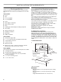
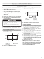
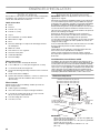
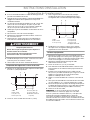
Cabinet Dimensions
*Spacer kit required
IMPORTANT:
Minimum distance “X”: 24" (61 cm) from electric cooking
surfaces.
Minimum distance “X”: 30" (76.2 cm) from gas cooking
surfaces.
Suggested maximum distance “X”: 36" (91.4 cm).
“X“ bottom
of canopy to
cooking surface
36" (91.4 cm) cabinet opening
42" (106.7 cm) cabinet opening*
48" (121.9 cm) cabinet opening*
Hood support must be
capable of supporting
75 lb (34 kg)
22" (55.9 cm)
hood liner depth

5
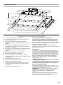
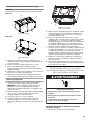
Product Dimensions
Venting Requirements
■ Vent system must terminate to the outdoors.
■ Do not terminate the vent system in an attic or other enclosed
area.
■ Do not use 4" (10.2 cm) laundry-type wall caps.
■ Use metal vent only. Rigid metal vent is recommended.
Plastic or metal foil vent is not recommended.
■ The length of vent system and number of elbows should be
kept to a minimum to provide efficient performance.
For the most efficient and quiet operation:
■ Use no more than three 90° elbows.
■ Make sure there is a minimum of 24" (61.0 cm) of straight
vent between the elbows if more than 1 elbow is used.
■ Do not install 2 elbows together.
■ Use clamps to seal all joints in the vent system.
■ Use caulking to seal exterior wall or roof opening around the
cap.
■ The size of the vent should be uniform.
Cold weather installations
An additional back draft damper should be installed to minimize
backward cold air flow and a thermal break should be installed to
minimize conduction of outside temperatures as part of the vent
system. The damper should be on the cold air side of the thermal
break.
The break should be as close as possible to where the vent
system enters the heated portion of the house.
Makeup air
Local building codes may require the use of makeup air systems
when using ventilation systems greater than specified CFM of air
movement. The specified CFM varies from locale to locale.
Consult your HVAC professional for specific requirements in your
area.
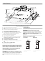
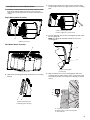
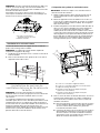
Venting Methods
Typical Internal Blower Motor System Venting
Installations
A 10" (25.4 cm) round vent system is needed for installation (not
included). The hood exhaust opening is 10" (25.4 cm) round.
NOTE: Flexible vent is not recommended. Flexible vent creates
back pressure and air turbulence that greatly reduce
performance.
Vent system can terminate either through the roof or wall. To vent
through the wall, a 90° elbow is needed.
27⁵⁄₈" (70.1 cm)
29¹³⁄₁₆" (75.8 cm)
4¹³⁄₁₆" (12.2 cm)
12³⁄₈"
(31.4 cm)
11¹⁄₂"
(29.2 cm)
5¹⁄₁₆"
(12.8 cm)
11" (27.9 cm)
18" (45.7 cm)
35⁷⁄₈" (91.1 cm)
10¹⁄₈" (25.7 cm)
22" (55.9 cm)
41⁷⁄₈" (106.4 cm) with 42" (106.7 cm) spacer kit
47⁷⁄₈" (121.6 cm) with 48" (121.9 cm) spacer kit
Roof Venting Wall Venting
A. 10" (25.4 cm) round vent
B. Roof cap
A. 10" (25.4 cm) round vent
B. Wall cap
A
B
B
A

6
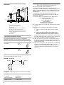
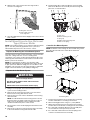
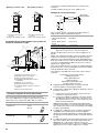
Typical In-line Blower Motor System Venting
Installations
Calculating Vent System Length
To calculate the length of the system you need, add the
equivalent feet (meters) for each vent piece used in the system.
The maximum equivalent vent lengths are:
10" (25.4 cm) round vents - 60 ft (18.3 m)
Example vent system
The following example falls within the maximum recommended
vent length.
Electrical Requirements
Observe all governing codes and ordinances.
Ensure that the electrical installation is adequate and in
conformance with National Electrical Code, ANSI/NFPA 70 (latest
edition), or CSA Standards C22.1-94, Canadian Electrical Code,
Part 1 and C22.2 No. 0-M91 (latest edition) and all local codes
and ordinances.
If codes permit and a separate ground wire is used, it is
recommended that a qualified electrician determine that the
ground path is adequate.
A copy of the above code standards can be obtained from:
National Fire Protection Association
1 Batterymarch Park
Quincy, MA 02169-7471
CSA International
8501 East Pleasant Valley Road
Cleveland, OH 44131-5575
■ A 120 volt, 60 Hz., AC only, 15-amp, fused electrical circuit is
required.
■ If the house has aluminum wiring, follow the procedure
below:
1. Connect a section of solid copper wire to the pigtail
leads.
2. Connect the aluminum wiring to the added section of
copper wire using special connectors and/or tools
designed and UL listed for joining copper to aluminum.
Follow the electrical connector manufacturer's recommended
procedure. Aluminum/copper connection must conform with
local codes and industry accepted wiring practices.
■ Wire sizes and connections must conform with the rating of
the appliance as specified on the model/serial rating plate.
The model/serial plate is located behind the filter on the rear
wall of the range hood.
■ Wire sizes must conform to the requirements of the National
Electrical Code, ANSI/NFPA 70 (latest edition), or CSA
Standards C22. 1-94, Canadian Electrical Code, Part 1 and
C22.2 No. 0-M91 (latest edition) and all local codes and
ordinances.
A. 10" (25.4 cm) round vent
B. Mount on top of ceiling joists.
C. Roof caps
D. Plywood (optional for some installations)
E. Mount on underside of roof rafters.
F. Mount from cross-members tied to trusses.
G. Duct horizontal; mount to cross-members
tied to trusses.
H. Wall cap
Vent Piece Equivalent Length
45° elbow 2.5 ft
(0.8 m)
90° elbow 5.0 ft
(1.5 m)
1 - 90° elbow = 5.0 ft (1.5 m)
1 - wall cap = 0.0 ft (0.0 m)
8 ft (2.4 m) straight = 8.0 ft (2.4 m)
Length of system = 13.0 ft (3.9 m)
F
G
D
A
A
B
C
D
A
A
H
E
90 elbow
6 ft (1.8 m)
2 ft
(0.6 m)
Wall cap

7
INSTALLATION INSTRUCTIONS
Prepare Location
■ It is recommended that the vent system be installed before
hood is installed.
■ Before making cutouts, make sure there is proper clearance
within the ceiling or wall for exhaust vent.
■ Hood liner is to be installed 24" (61.0 cm) minimum for
electric cooking surfaces, 30" (76.2 cm) minimum for gas
cooking surfaces, to a suggested maximum of 36" (91.4 cm)
above the cooking surface.
■ Check that all installation parts have been removed from the
shipping carton.
1. Disconnect power.
2. Determine which venting method to use: roof or wall exhaust.
3. Select a flat surface for assembling the range hood. Place
covering over that surface.
4. Using 2 or more people, lift hood liner onto covered surface.
5. Remove the filters. See the “Range Hood Care” section.
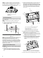
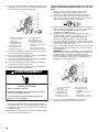
Hood Liner Support Preparation
1. Mark the locations for the four ¹⁄₈" (3 mm) diameter holes on
the hood support as shown.
2. Using a ¹⁄₈" (3 mm) drill bit, drill the 4 holes.
3. Mark the cutout for the rectangular clearance hole for the
upper hood liner housing as shown.
4. Using a jigsaw or keyhole saw, cut out the rectangular
clearance hole for the upper hood liner housing.
Complete Preparation
1. Determine and make all necessary cuts in the wall or roof for
the vent system. Install the vent system before installing the
range hood. See the “Venting Requirements” section.
2. Determine the location where the power supply cable will be
run through the wall.
3. Drill a 1¹⁄₄" (3.2 cm) hole at this location.
4. Pull enough power supply cable through the wall to allow for
easy connection to the terminal box.
5. Install the 10" (25.4 cm) square x 10" (25.4 cm) round vent
transition with damper to top of the range hood liner using
four 4.2 x 8 mm screws.
6. Remove terminal box cover and set aside.
7. Remove knockout from the top of the vent hood and install a
UL listed or CSA approved ¹⁄₂" (1.3 cm) strain relief.
8. Place the range hood near its mounting position and run the
power supply cable through the strain relief into terminal box
(enough to make connection).
9. Tighten the strain relief screws.
NOTE: Your range hood requires you to purchase either an
internal type or an in-line (external type) blower motor system.
For internal blower systems, there are blower motor mounting
parts in the blower motor installation packet that must be added
to the range hood prior to mounting the range hood. See the
“Install Range Hood Internal Blower Motor” section and the
instructions supplied with the blower motor.
A. Wall
B. Centerline
C. 6" (15.2 cm)
D. 10
¹⁄₈
" (25.7 cm)
E. 14
¹⁵⁄₁₆
" (38.0 cm)
F. 2 9
¹³⁄₁₆
" (75.8 cm)
G.
¹⁄₈
"
(3 mm) hole
diameter
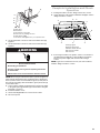
WARNING
Excessive Weight Hazard
Use two or more people to move and install
range hood.
Failure to do so can result in back or other injury.
A
B
C
D
E
F
G
A. Wall
B. Centerline
C. 4
¹⁄₂
" (11.4 cm)
D. 13" (33.0 cm)
E. 14" (35.5 cm)
F. 28" (71.1 cm)
G.Hood support
A
B
C
D
E
F
G

8
NOTE: For 42" (106.7 cm) and 48" (121.9 cm) wide cabinet
openings, a spacer kit is required. The kit must be assembled to
the range hood prior to mounting the hood to the cabinet.
See “Accessories” in the “Assistance or Service” section to order.
The assembly instructions come with the spacer kits.
Install Range Hood Liner
The hood liner attaches to the hood support using four mounting
screws and washers.
NOTE: Hood support must be capable of supporting 75 lb
(34 kg).
1. Using 2 or more people, lift the hood liner into place.
2. Install the hood liner using four 5 x 45 mm screws to the hood
support and tighten securely.
Install Hood Liner Internal Blower
Motor
NOTE: Your hood liner requires you to purchase either an internal
type or an in-line (external type) blower motor system. See
“Blower Motor System” in the “Accessories” section.
The internal blower system can be mounted for top venting or
rear venting. For top venting, the mounting bracket and spring
clip that come with the blower system will mount to the top panel
of the hood liner. For rear venting, the mounting bracket and
spring clip that come with the blower system will mount to the
rear panel of the hood liner.
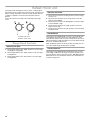
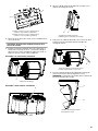
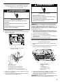
Prepare the Internal Blower System
IMPORTANT: Perform steps 1-4 before mounting the hood liner.
1. Remove grease filters from hood liner. See the “Range Hood
Care” section.
2. Install the motor support bracket using three 4.2 x 8 mm
screws. Screw bracket to the inside top or back (alternate
location on some models), toward the left side of the hood
liner.
3. Install motor spring clip using two 4.2 x 8 mm screws. Screw
spring clip to the inside top or back (alternate location on
some models) of the hood liner at the proper location for the
selected motor system. Slide the mounting tab of the spring
clip through the slot in the panel and secure with the screws.
Use the inside set of mounting holes for the single motor
system. Use the outside set of mounting holes for the dual
motor system.
4. Install the 6 mm nuts to the outside top or outside back
(alternate location on some models) of the hood liner at the
proper location for the selected motor system.
■ Two 6 mm nuts are required for the single motor system.
Clip nuts into the small square notches located at the left
and right end of the square vent opening.
■ Five 6 mm nuts are required for the dual motor system.
Clip nuts into the small square notches, one located in the
front of the square vent opening and the other four
located at the left and right ends of the square vent
opening.
5. Mount hood liner. See the “Install Range Hood Liner” section.
A. 42" (106.7 cm) or 48" (121.9 cm)
spacer kit
B. Range Hood
A
A
B
A. 4.2 x 8 mm screws (3) for motor support bracket
B. 4.2 x 8 mm screws (2) for motor spring clip
C. Motor support bracket
D. Motor spring clip (single motor assembly location)
E. Motor spring clip (dual motor assembly location)
A. Clip nut (6 mm) locations for dual motor assembly (quantity 5)
B. Clip nut (6 mm) locations for single motor assembly (quantity 2)
C
A
B
D
E
A
A
A
B

9
Install Hood Liner Internal Blower Motor
1. Install the hood liner blower motor assembly inside the hood
liner canopy with the wiring connection to the left for the
single motor system and to the front or top for the dual motor
system.
Single Blower Motor Assembly
Dual Blower Motor Assembly
2. Slide the left mounting plate flange under the motor mounting
bracket.
3. Run the power supply wires and connector from the range
hood through the hole in the right end of the motor mounting
plate.
4. Push the right end of the motor mounting plate up and snap it
into the spring tab.
NOTE: The spring tab should be outside the slot in the
mounting plate.
5. Align mounting holes in motor mounting plate with motor
mounting clip nuts and install 6 x 16 mm screws and 6.4 mm
lock washers (quantity 2 for single motor; quantity 5 for dual
motor).
A. Wiring connection
A. Wiring connection
A. Motor mounting bracket
B. Mounting plate left flange
A
A
B
A
A. Motor mounting plate hole
B. Power supply wires and connector
A. Motor mounting plate
B. Spring clip
A. Screw with lock washer
B. Mounting hole in motor mounting plate
C. Clip nut (6 mm)
A
B
A
B
A
B
C

10
6. Attach power cord connector from the range hood to
connector on wiring box.
7. Go to the “Make Electrical Power Supply Connection to Hood
Liner” section.
Install Hood Liner In-line (External
Type) Blower Motor
NOTE: Your hood liner requires you to purchase either an internal
type or an in-line (external type) blower motor system. See
“Blower Motor System” in the “Accessories” section.
Prepare for Mounting the In-line Blower System
The in-line blower system must be fastened to a secure structure
of the roof, ceiling, wall, floor, or new or existing frame
construction. The 4 holes on either the inlet (bottom) side or the
outlet (top) side of the blower must be used to mount the in-line
blower system to the structure.
NOTE: The mounting hole locations must span the studs.
Additional stud framing may be required. Plywood may be used
to span open areas between ceiling joists or roof rafters to aid
installation. This structure must be strong enough to support the
weight of the in-line blower system (50 lb [22.6 kg] min).
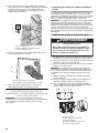
Prepare the In-line Blower System
1. Using 2 or more people, move the in-line blower motor
system to the mounting location.
2. Remove the 10 screws from the front cover of the in-line
blower motor housing and set them aside.
3. Remove the front cover of the in-line blower motor housing
and set it aside.
NOTE: To make the blower motor housing easier to mount,
the blower motor assembly can be removed. If you do not
want to remove the blower motor assembly, proceed to
“Install In-line Blower System” in this section.
4. Disconnect the motor electrical plug from the blower motor
assembly.
5. Remove the screws that secure the blower motor assembly
to the in-line blower housing and set them aside.
6. Pull the spring clip to release the blower motor assembly.
Remove the blower motor assembly from the housing and
place it on a covered surface.
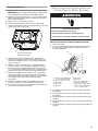
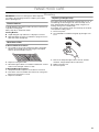
Install In-line Blower System
NOTE: The blower motor housing can be mounted using 4 holes
from either the inlet side or the outlet side of the blower.
Outlet Side
Inlet Side
1. Position the in-line blower motor housing in its mounting
location and mark the 4 mounting hole locations.
2. Drill 4 mounting pilot holes using a ³⁄₁₆" (5 mm) drill bit.
3. Attach the in-line blower motor housing to the mounting
location with four 6 x 80 mm mounting screws and washers.
4. If it is removed, reinstall the blower motor assembly and
secure it with the screws previously removed.
5. If it is removed, reattach the motor electrical plug to the
connector on the blower motor assembly.
A. Wiring box connector
B. Power supply connector
from range hood
B
A
WARNING
Excessive Weight Hazard
Use two or more people to move and install in-line
blower motor system.
Failure to do so can result in back or other injury.
A. Front cover
B. Blower mounting screws
C. Spring clip
D. Bottom housing mounting holes
E. Motor electrical plug
A. Mounting holes
A. Mounting holes
A
B
C
D
A
A
A
A
A
A

11
Complete Preparation
1. Determine and make all necessary cuts for the vent system.
IMPORTANT: When cutting or drilling into the ceiling or wall,
do not damage electrical wiring or other hidden utilities.
2. Determine the location where the ¹⁄₂" (1.3 cm) wiring conduit
will be routed through the ceiling or wall between the in-line
blower and the hood liner.
3. Drill a 1¹⁄₄" (3.2 cm) hole at this location.
4. Locate the electrical terminal boxes in the in-line blower
housing and hood liner. Remove the terminal box covers and
set the covers and screws aside.
5. Remove the electrical knockout from the in-line blower
housing and hood liner to prepare for the installation of the
UL listed or CSA approved ¹⁄₂" (1.3 cm) wiring conduit and
conduit connector.
6. With the hood liner mounted (see the “Install Hood Liner”
section), run the ¹⁄₂" (1.3 cm) wiring conduit between the in-
line blower motor housing and the hood liner. Pull enough
¹⁄₂" (1.3 cm) wiring conduit to allow for easy connection to the
terminal boxes in the in-line blower housing and hood liner.
7. Run the six 18 AWG wires through the ¹⁄₂" (1.3 cm) wiring
conduit and conduit connectors and into the terminal boxes
on the in-line blower housing and hood liner. Leave enough
wire length in each terminal box to make the wiring
connections.
8. Install the conduit connectors and conduit to the in-line
blower housing and hood liner electrical terminal boxes.
9. Connect the vent system to the hood liner and in-line blower
system and seal all joints with clamps.
Make Electrical Connections for
In-line Blower Motor System
Electrical Connection Inside In-line Blower System
1. Disconnect power.
2. Connect the wires from the wiring conduit to the wires from
the motor electrical plug cable inside the in-line blower
housing terminal box.
3. Use UL listed wire connectors and connect the black wires
(C) together.
4. Use UL listed wire connectors and connect the white wires
(D) together.
5. Use UL listed wire connectors and connect the red wires (E)
together.
6. Use UL listed wire connectors and connect the blue wires (F)
together.
7. Use UL listed wire connectors and connect the gray wires (G)
together.
A. Electrical terminal box
B. Electrical knockout
A
B
A. UL listed or CSA approved
¹⁄₂
" (1.3 cm) wiring conduit
B. UL listed wire connectors
C. Black wires
D. White wires
E. Red wires
F. Blue wires
G. Gray wires
H. Green (or yellow/green)
and green/yellow wires
I. Motor electrical plug cable
J. UL listed or CSA approved
¹⁄₂
" (1.3 cm) strain relief
WARNING
Electrical Shock Hazard
Disconnect power before servicing.
Replace all parts and panels before operating.
Failure to do so can result in death or electrical shock.
A
B
C
D
E
F
G
H
I
J

12
8. Connect the green (or yellow/green) ground wire to the
green/yellow ground wire (H) in the terminal box using UL
listed wire connectors.
9. Reinstall the in-line blower terminal box cover and screw.
10. Reinstall the front cover of the in-line blower housing and
secure it with 10 mounting screws.
Electrical Connection Inside Hood Liner Between
In-line Blower System and Hood Liner
1. With the hood liner mounted (see the “Install Hood Liner”
section), locate the wiring cable connector inside the hood
liner.
2. Connect the 6-wire connector assembly supplied with the
in-line blower motor system to the mating cable connector
from the hood liner.
3. Locate the terminal box inside the hood liner and install a
¹⁄₂" (1.3 cm) UL listed or CSA approved strain relief (see
“Complete Preparation” in the “Prepare Location” section).
4. Run the wire ends from the 6-wire connector assembly
through the ¹⁄₂" (1.3 cm) strain relief, leaving enough wire
length to make the wiring connections. Tighten the strain
relief screws.
5. Connect the wires from the 6-wire connector assembly to the
wires from the wiring conduit inside the hood liner terminal
box.
6. Connect the same color wires to each other (black to black,
white to white, etc.) using UL listed wire connectors.
NOTE: Connect the green (or green/yellow) ground wire from
the wiring conduit to the green (or bare) ground wire from the
home power supply using UL listed wire connectors (see the
“Make Electrical Power Supply Connection to Hood Liner”
section).
7. Go to the “Make Electrical Power Supply Connection to Hood
Liner” section.
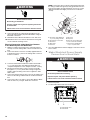
Make Electrical Power Supply
Connection to Hood Liner
1. Disconnect power.
2. Locate terminal box inside of the hood liner.
WARNING
Electrical Shock Hazard
Electrically ground blower.
Connect ground wire to green and yellow ground wire
in terminal box.
Failure to do so can result in death or electrical shock.
A. UL listed or CSA approved
¹⁄₂
" (1.3 cm) wiring conduit
B. UL listed wire connectors
C. Black wires
D. White wires
E. Red wires
F. Bl ue wir es
G. Gray wires
H. Green (or green/yellow) wire
I. 6-wire connector assembly
J. UL listed or CSA approved
¹⁄₂
" (1.3 cm) strain relief
A. Terminal box cover
B. Terminal box
A
B
C
D
E
F
G
H
I
J
WARNING
Electrical Shock Hazard
Disconnect power before servicing.
Replace all parts and panels before operating.
Failure to do so can result in death or electrical shock.
A
B

13
3. Use UL listed wire connectors and connect black wires (B)
together.
4. Use UL listed wire connectors and connect white wires (A)
together.
NOTE: When using an in-line blower motor system, the green (or
green/yellow) ground wire in the conduit from the in-line blower
motor system is to be connected with the green (or bare) wire of
the home power supply cable and with the green/yellow wire (D)
in the terminal box.
5. Connect green (or bare) ground wire from home power supply
to the green/yellow ground wire (D) in terminal box using UL
listed wire connectors.
6. Install terminal box cover.
7. Check that all light bulbs are secure in their sockets.
8. Reconnect power.
Complete Installation and Check
Operation
1. Install grease filters. See the “Range Hood Care” section.
2. Check operation of the range hood blower and lights. See the
“Range Hood Use” section.
3. If the range hood does not operate, check to see whether a
circuit breaker has tripped or a household fuse has blown.
Disconnect power supply and check that the wiring is
correct.
NOTE: To get the most efficient use from your new hood liner,
read the “Range Hood Use” section.
A. White wires
B. Black wires
C. UL listed wire connectors
D. Green, bare or yellow/green wires
E. Home power supply
F. UL listed or CSA approved
¹⁄₂
" (1.3 cm) strain relief
A
B
C
D
E
F
WARNING
Electrical Shock Hazard
Electrically ground blower.
Connect ground wire to green and yellow ground wire
in terminal box.
Failure to do so can result in death or electrical shock.
A. Halogen lights
B. Halogen light switch
C. Blower control switches
D. Grease filter handle
E. Grease filter
C
A
A
A
A
B
D
E

14
RANGE HOOD USE
The range hood is designed to remove smoke, cooking vapors
and odors from the cooktop area. For best results, start the hood
before cooking and allow it to operate several minutes after the
cooking is complete to clear all smoke and odors from the
kitchen.
The hood controls are located on the underside of the range
hood.
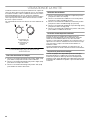
Range Hood Controls
Operating the lights
1. Turn the light switch to the “Night” position to use the range
hood lights as a night light.
2. Turn the light switch to the “High” position to turn the range
hood lights On.
3. Turn the light switch to the “Off” position to turn the range
hood lights Off.
Operating the blower
1. Turn the blower switch to the first position to turn the range
hood on Low.
2. Turn the blower switch to the second position to turn the
range hood on Medium.
3. Turn the blower switch to the third position to turn the range
hood on Medium - High.
4. Turn the blower switch to the “High” position to turn the
range hood on High.
5. Turn the blower switch to the “Off” position to turn the range
hood blower Off.
Auto On Blower
The range hood is equipped with a sensor to automatically turn
on the blower when excessive heat is detected in the control
area. When the blower switch is in the “Off” position, this sensor
will turn the blower to high speed when necessary. When the heat
decreases, the blower will turn off.
When the blower switch is in the On position, the heat sensor is
not active and the range hood functions normally.
Thermal Protector
The range hood is equipped with a thermal protector to avoid
overheating conditions. If the range hood shuts off while in use,
move the blower switch to the “Off” position. Wait approximately
60 minutes, then move the blower switch to the first position to
restart the range hood.
A. Halogen light switch
B. Blower control switch
A
B

15
RANGE HOOD CARE
Cleaning
IMPORTANT: Clean the hood and grease filters frequently
according to the following instructions. Replace grease filters
before operating hood.
Exterior Surfaces:
To avoid damage to the exterior surface, do not use steel wool or
soap-filled scouring pads.
Always wipe dry to avoid water marks.
Cleaning Method:
■ Liquid detergent soap and water, or all-purpose cleanser
■ Wipe with damp soft cloth or nonabrasive sponge, then rinse
with clean water and wipe dry.
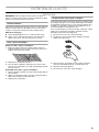
Metal Grease Filter
To Remove Metal Grease Filters:
1. Use 2 hands to remove the metal grease filters. Grasp filter
handles, push toward the rear of the range hood and pull
down on the front handle to remove.
2. Repeat for each grease filter.
3. Wash metal grease filters as needed in a dishwasher or hand
wash in a hot detergent solution to clean.
To Reinstall Metal Grease Filters:
1. Grasp filter handles and place rear of filter into rear track.
2. Push down on the rear handle and set the front of the grease
filter into the front track to secure.
3. Repeat for each filter.
Replacing a Halogen Lamp
Turn off the range hood and allow the halogen lamp to cool. To
avoid damage or decreasing the life of the new lamp, do not
touch lamp with bare fingers. Replace lamp, using tissue or
wearing cotton gloves to handle lamp.
If new lights do not operate, make sure the lamps are inserted
correctly before calling service.
1. Disconnect power.
2. Use a flat-blade screwdriver and gently pry the light cover
loose.
3. Remove the lamp and replace with a 120-volt, 40-watt
maximum, halogen lamp made for a G-9 base.
4. Replace the light cover.
5. Reconnect power.

16
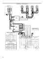
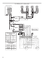
WIRING DIAGRAM
SE13RA
M
M
Junction box
GND
N
L
Y/G
WBK
BK
BK
BK
BK BK
BK
BK
BK
W
WWW
Y
Y
YY Y
Y
Y
Y
Y
Y
Y
Y
BR
BR
W
Light
switch
Thermo
switch
Motor
switch
W
R
GY
W
R
GY
BU
BU
25uF 25uF
BR BR
BU GY
BK
R
W
Y/G
BR BR
YYBU
GY R
W Y/G
Single or double motor
Optional kit
a
c
1
2
3
a
e
1
2
3
4
5
1
23
V
1
Motor Resistance
(Ohms)
Blue - Black
9.8Ω max.
Blue - Gray
14.3Ω
Blue - Red
18Ω
Blue - White
21.6Ω min.
Room temp. 73.4˚F (23˚C)
Motor
Characteristics
Power supply
120 VAC
Frequency
60 Hz
Power absorption
420 W
Current
3.7 A

17
ASSISTANCE OR SERVICE
When calling for assistance or service, please know the purchase
date and the complete model and serial number of your
appliance. This information will help us to better respond to your
request.
If you need replacement parts
If you need to order replacement parts, we recommend that you
use only factory specified parts. Factory specified parts will fit
right and work right because they are made with the same
precision used to build every new appliance. To locate factory
specified replacement parts in your area, call us or your nearest
designated service center.
In the U.S.A.
If the problem is not due to one of the items listed in
the “Troubleshooting” section…
Call the dealer from whom your appliance was purchased, or call
Jenn-Air at 1-800-JENNAIR (1-800-536-6247) to locate an
authorized service company. When calling, please know the
purchase date and the complete model and serial number of your
appliance. Be sure to retain proof of purchase to verify warranty
status.
If the dealer or service company cannot resolve your problem,
write to:
Jenn-Air Brand Home Appliances
Customer eXperience Center
553 Benson Road
Benton Harbor, MI 49022-2692
Web address: www.jennair.com
Or call: 1-800-JENNAIR (1-800-536-6247)
U.S. customers using TTY for deaf, hearing impaired or speech
impaired, call: 1-800-688-2080.
NOTE: When writing or calling about a service problem, please
include the following information:
1. Your name, address and daytime telephone number.
2. Appliance model number and serial number.
3. Name and address of your dealer or servicer.
4. A clear description of the problem you are having.
5. Proof of purchase (sales receipt).
User’s guides, service manuals and parts information are
available from Jenn-Air Brand Home Appliances, Customer
eXperience Center.
In Canada
If the problem is not due to one of the items listed in
the “Troubleshooting” section…
Call the dealer from whom your appliance was purchased, or call
Jenn-Air at 1-800-JENNAIR (1-800-536-6247) to locate an
authorized service company. When calling, please know the
purchase date and the complete model and serial number of your
appliance. Be sure to retain proof of purchase to verify warranty
status.
If the dealer or service company cannot resolve your problem,
write to:
Jenn-Air Brand Home Appliances
Customer eXperience Centre
200 - 6750 Century Ave.
Mississauga, ON L5N 0B7
Web address: www.jennair.ca
Or call: 1-800-JENNAIR (1-800-536-6247).
NOTE: When writing or calling about a service problem, please
include the following information:
1. Your name, address and daytime telephone number.
2. Appliance model number and serial number.
3. Name and address of your dealer or servicer.
4. A clear description of the problem you are having.
5. Proof of purchase (sales receipt).
User’s guides, service manuals and parts information are
available from Jenn-Air Brand Home Appliances, Customer
eXperience Centre.
Accessories
Blower Motor Systems (1 system is required)
NOTE: Internal Blower Motor Systems: UXB0600DYS - 600 CFM
Internal Blower Motor System is for use in the 36" (91.4 cm) hood
liner above a cooktop with a maximum of 65,000 Btus.
Use UXB1200DYS - 1200 CFM Internal Blower Motor System
above cooktops rated higher than 65,000 Btus.
600 CFM Internal Blower Motor System - Order Model Number
UXB0600DYS
1200 CFM Internal Blower Motor System - Order Model Number
UXB1200DYS
1200 CFM In-Line Blower Motor System - Order Model Number
UXI1200DYS
Spacer Kits (contain [2] spacers and [8] screws)
42" (106.7 cm) cabinet opening - Order Part Number W10646268
48" (121.9 cm) cabinet opening - Order Part Number W10646269

18
JENN-AIR
®
MAJOR APPLIANCE WARRANTY
ONE YEAR LIMITED WARRANTY
For one year from the date of purchase, when this major appliance is installed, operated and maintained according to instructions
attached to or furnished with the product, Jenn-Air brand of Whirlpool Corporation or Whirlpool Canada LP (hereafter “Jenn-Air”) will
pay for factory specified replacement parts and repair labor to correct defects in materials or workmanship that existed when this major
appliance was purchased.
YOUR SOLE AND EXCLUSIVE REMEDY UNDER THIS LIMITED WARRANTY SHALL BE PRODUCT REPAIR AS PROVIDED HEREIN.
Service must be provided by a Jenn-Air designated service company. This limited warranty is valid only in the United States or Canada
and applies only when the major appliance is used in the country in which it was purchased. Outside the 50 United States and Canada,
this limited warranty does not apply. This limited warranty is effective from the date of original consumer purchase. Proof of original
purchase date is required to obtain service under this limited warranty.
ITEMS EXCLUDED FROM WARRANTY
This limited warranty does not cover:
1. Service calls to correct the installation of your major appliance, to instruct you on how to use your major appliance, to replace or
repair house fuses, or to correct house wiring or plumbing.
2. Service calls to repair or replace appliance light bulbs, air filters or water filters. Consumable parts are excluded from warranty
coverage.
3. Replacement parts or repair labor if this major appliance is used for other than normal, single-family household use or when it is
used in a manner that is contrary to published user or operator instructions and/or installation instructions.
4. Damage resulting from accident, alteration, misuse, abuse, fire, flood, acts of God, improper installation, installation not in
accordance with electrical or plumbing codes, or use of products including but not limited to consumables or cleaning products not
approved by Jenn-Air.
5. Cosmetic damage, including scratches, dents, chips or other damage to the finish of your major appliance, unless such damage
results from defects in materials or workmanship and is reported to Jenn-Air within 30 days from the date of purchase.
6. Any food loss due to refrigerator or freezer product failures.
7. Costs associated with the removal from your home of your major appliance for repairs. This major appliance is designed to be
repaired in the home and only in-home service is covered by this warranty.
8. Repairs to parts or systems resulting from unauthorized modifications made to the appliance.
9. Expenses for travel and transportation for product service if your major appliance is located in a remote area where service by an
authorized Jenn-Air servicer is not available.
10. The removal and reinstallation of your major appliance if it is installed in an inaccessible location or is not installed in accordance
with published installation instructions.
11. Replacement parts or repair labor for major appliances with original model/serial numbers that have been removed, altered or
cannot be easily determined. This warranty is void if the factory applied serial number has been altered or removed from your major
appliance.
12. Removal or replacement of trim, decorative panels, flooring, cabinetry, islands, countertops, drywall or other built-in fixtures that
interfere with servicing, removal or replacement of the product.
The cost of repair or replacement under these excluded circumstances shall be borne by the customer.
DISCLAIMER OF IMPLIED WARRANTIES
IMPLIED WARRANTIES, INCLUDING ANY IMPLIED WARRANTY OF MERCHANTABILITY OR IMPLIED WARRANTY OF FITNESS FOR
A PARTICULAR PURPOSE, ARE LIMITED TO ONE YEAR OR THE SHORTEST PERIOD ALLOWED BY LAW. Some states and provinces
do not allow limitations on the duration of implied warranties of merchantability or fitness, so this limitation may not apply to you. This
warranty gives you specific legal rights, and you also may have other rights that vary from state to state or province to province.
DISCLAIMER OF REPRESENTATIONS OUTSIDE OF WARRANTY
Jenn-Air makes no representations about the quality, durability, or need for service or repair of this major appliance other than the
representations contained in this warranty. If you want a longer or more comprehensive warranty than the limited warranty that comes
with this major appliance, you should ask Jenn-Air or your retailer about buying an extended warranty.
LIMITATION OF REMEDIES; EXCLUSION OF INCIDENTAL AND CONSEQUENTIAL DAMAGES
YOUR SOLE AND EXCLUSIVE REMEDY UNDER THIS LIMITED WARRANTY SHALL BE PRODUCT REPAIR AS PROVIDED HEREIN.
JENN-AIR SHALL NOT BE LIABLE FOR INCIDENTAL OR CONSEQUENTIAL DAMAGES. Some states and provinces do not allow the
exclusion or limitation of incidental or consequential damages, so these limitations and exclusions may not apply to you. This warranty
gives you specific legal rights, and you also may have other rights that vary from state to state or province to province.
If outside the 50 United States and Canada, contact your authorized Jenn-Air dealer to determine if another warranty applies.
If you need service, first see the “Troubleshooting” section of the Use & Care Guide. After checking “Troubleshooting,” you may find
additional help by checking the “Assistance or Service” section or by calling us at 1-800-JENNAIR (1-800-536-6247). 2/13

19
Keep this book and your sales slip together for future
reference. You must provide proof of purchase or installation
date for in-warranty service.
Write down the following information about your major appliance
to better help you obtain assistance or service if you ever need it.
You will need to know your complete model number and serial
number. You can find this information on the model and serial
number label located on the product.
Dealer name____________________________________________________
Address________________________________________________________
Phone number__________________________________________________
Model number __________________________________________________
Serial number __________________________________________________
Purchase date __________________________________________________

20
SÉCURITÉ DE LA HOTTE DE CUISINIÈRE
Risque possible de décès ou de blessure grave si vous ne
suivez pas immédiatement les instructions.
Risque possible de décès ou de blessure grave si vous
ne suivez pas les instructions.
Tous les messages de sécurité vous diront quel est le danger potentiel et vous disent comment réduire le risque de blessure et
ce qui peut se produire en cas de non-respect des instructions.
Votre sécurité et celle des autres est très importante.
Nous donnons de nombreux messages de sécurité importants dans ce manuel et sur votre appareil ménager. Assurez-vous de
toujours lire tous les messages de sécurité et de vous y conformer.
AVERTISSEMENT
DANGER
Voici le symbole d’alerte de sécurité.
Ce symbole d’alerte de sécurité vous signale les dangers potentiels de décès et de blessures graves à vous
et à d’autres.
Tous les messages de sécurité suivront le symbole d’alerte de sécurité et le mot “DANGER” ou
“AVERTISSEMENT”. Ces mots signifient :
Avertissements de la proposition 65 de l'État de Californie :
AVERTISSEMENT : Ce produit contient au moins un produit chimique connu par l’État de Californie pour être à l’origine de
cancers.
AVERTISSEMENT : Ce produit contient au moins un produit chimique connu par l’État de Californie pour être à l’origine de
malformations et autres déficiences de naissance.
La page est en cours de chargement...
La page est en cours de chargement...
La page est en cours de chargement...
La page est en cours de chargement...
La page est en cours de chargement...
La page est en cours de chargement...
La page est en cours de chargement...
La page est en cours de chargement...
La page est en cours de chargement...
La page est en cours de chargement...
La page est en cours de chargement...
La page est en cours de chargement...
La page est en cours de chargement...
La page est en cours de chargement...
La page est en cours de chargement...
La page est en cours de chargement...
-
 1
1
-
 2
2
-
 3
3
-
 4
4
-
 5
5
-
 6
6
-
 7
7
-
 8
8
-
 9
9
-
 10
10
-
 11
11
-
 12
12
-
 13
13
-
 14
14
-
 15
15
-
 16
16
-
 17
17
-
 18
18
-
 19
19
-
 20
20
-
 21
21
-
 22
22
-
 23
23
-
 24
24
-
 25
25
-
 26
26
-
 27
27
-
 28
28
-
 29
29
-
 30
30
-
 31
31
-
 32
32
-
 33
33
-
 34
34
-
 35
35
-
 36
36


Jenn-Air JXL6536CSS Guide d'installation
- Catégorie
- Hottes
- Taper
- Guide d'installation
dans d''autres langues
Autres documents
-
KitchenAid 36 Inch and 48 Inch Hood Liner Guide d'installation
-
KitchenAid UVL6048JSS Le manuel du propriétaire
-
Whirlpool UVL6036JSS Mode d'emploi
-
JennAir JXL6536HSS Le manuel du propriétaire
-
Maytag 48" Manuel utilisateur
-
KitchenAid KXW9748YSS Manuel utilisateur
-