Simplicity 030334-0 Manuel utilisateur
- Catégorie
- Groupes électrogènes
- Taper
- Manuel utilisateur

Printed in U.S.A. Manual No. 203985GS Revision A (08/14/2008)
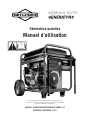
Portable Generator
Operator’s Manual
BRIGGS & STRATTON POWER PRODUCTS GROUP, LLC
JEFFERSON, WISCONSIN, U.S.A.
This generator is rated and certified to be compliant with CSA (Canadian
Standards Association) standard C22.2 No. 100-04 (motors and generators).

2 BRIGGSandSTRATTON.COM
Briggs & Stratton Power Products Group, LLC
900 North Parkway
Jefferson, WI 53549
Copyright © 2008 Briggs & Stratton Power Products Group,
LLC. All rights reserved. No part of this material may be
reproduced or transmitted in any form by any means without
the express written permission of Briggs & Stratton Power
Products Group, LLC.
Thank you for purchasing this quality-built Briggs & Stratton generator. We are pleased that you’ve placed your confidence in
the Briggs & Stratton brand. When operated and maintained according to the instructions in this manual, your Briggs &
Stratton generator will provide many years of dependable service.
This manual contains safety information to make you aware of the hazards and risks associated with generator products and
how to avoid them. This generator is designed and intended only for supplying electrical power for operating compatible
electrical lighting, appliances, tools and motor loads, and is not intended for any other purpose. It is important that you read
and understand these instructions thoroughly before attempting to start or operate this equipment. Save these instructions for
future reference.
This generator requires final assembly before use. Refer to the Assembly section of this manual for instructions on final
assembly procedures. Follow the instructions completely.
Where to Find Us
You never have to look far to find Briggs & Stratton support and service for your generator. Consult your Yellow Pages. There
are over 30,000 Briggs & Stratton authorized service dealers worldwide who provide quality service. You can also contact
Briggs & Stratton Customer Service by phone at (800) 743-4115 or on the Internet at BRIGGSandSTRATTON.COM.
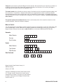
Generator
Model Number
Revision
Serial Number
Engine
Model Number
Type Number
Code Number
Date Purchased

Table of Contents
Operator Safety . . . . . . . . . . . . . . . . . . . . . . . . . . . . . . . . . 4
Equipment Description. . . . . . . . . . . . . . . . . . . . . . . . . . . . . . . . . . . . . . . . . 4
Important Safety Information. . . . . . . . . . . . . . . . . . . . . . . . . . . . . . . . . . . . 4
Assembly . . . . . . . . . . . . . . . . . . . . . . . . . . . . . . . . . . . . . 7
Unpack Generator . . . . . . . . . . . . . . . . . . . . . . . . . . . . . . . . . . . . . . . . . . . . 7
Install Wheel Kit. . . . . . . . . . . . . . . . . . . . . . . . . . . . . . . . . . . . . . . . . . . . . . 7
Add Engine Oil . . . . . . . . . . . . . . . . . . . . . . . . . . . . . . . . . . . . . . . . . . . . . . . 8
Add Fuel. . . . . . . . . . . . . . . . . . . . . . . . . . . . . . . . . . . . . . . . . . . . . . . . . . . . 8
Attach Negative Battery Cable . . . . . . . . . . . . . . . . . . . . . . . . . . . . . . . . . . . 8
System Ground . . . . . . . . . . . . . . . . . . . . . . . . . . . . . . . . . . . . . . . . . . . . . . 9
Connecting to a Building’s Electrical System. . . . . . . . . . . . . . . . . . . . . . . . 9
Generator Location . . . . . . . . . . . . . . . . . . . . . . . . . . . . . . . . . . . . . . . . . . . 9
Features and Controls . . . . . . . . . . . . . . . . . . . . . . . . . . . . 10
Cord Sets and Receptacles . . . . . . . . . . . . . . . . . . . . . . . . . . . . . . . . . . . . 11
Battery Float Charger . . . . . . . . . . . . . . . . . . . . . . . . . . . . . . . . . . . . . . . . . 11
Operation . . . . . . . . . . . . . . . . . . . . . . . . . . . . . . . . . . . . 12
Starting the Engine . . . . . . . . . . . . . . . . . . . . . . . . . . . . . . . . . . . . . . . . . . 12
Connecting Electrical Loads. . . . . . . . . . . . . . . . . . . . . . . . . . . . . . . . . . . . 13
Oil Pressure Shutdown . . . . . . . . . . . . . . . . . . . . . . . . . . . . . . . . . . . . . . . 13
Stopping the Engine. . . . . . . . . . . . . . . . . . . . . . . . . . . . . . . . . . . . . . . . . . 13
Cold Weather Operation. . . . . . . . . . . . . . . . . . . . . . . . . . . . . . . . . . . . . . . 13
Don’t Overload Generator . . . . . . . . . . . . . . . . . . . . . . . . . . . . . . . . . . . . . 15
Maintenance . . . . . . . . . . . . . . . . . . . . . . . . . . . . . . . . . . 16
Maintenance Schedule. . . . . . . . . . . . . . . . . . . . . . . . . . . . . . . . . . . . . . . . 16
Generator Maintenance . . . . . . . . . . . . . . . . . . . . . . . . . . . . . . . . . . . . . . . 16
Battery Maintenance . . . . . . . . . . . . . . . . . . . . . . . . . . . . . . . . . . . . . . . . . 16
Fuel Valve Maintenance . . . . . . . . . . . . . . . . . . . . . . . . . . . . . . . . . . . . . . . 17
Engine Maintenance. . . . . . . . . . . . . . . . . . . . . . . . . . . . . . . . . . . . . . . . . . 17
Storage . . . . . . . . . . . . . . . . . . . . . . . . . . . . . . . . . . . . . . . . . . . . . . . . . . . 20
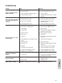
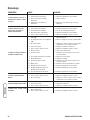
Troubleshooting . . . . . . . . . . . . . . . . . . . . . . . . . . . . . . . . 21
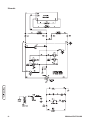
Schematic . . . . . . . . . . . . . . . . . . . . . . . . . . . . . . . . . . . . . . . . . . . . . . . . . 22
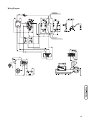
Wiring Diagram . . . . . . . . . . . . . . . . . . . . . . . . . . . . . . . . . . . . . . . . . . . . . 23
Warranties. . . . . . . . . . . . . . . . . . . . . . . . . . . . . . . . . . . . 24
Emissions Control System Warranty . . . . . . . . . . . . . . . . . . . . . . . . . . . . . 24
Generator Owner Warranty . . . . . . . . . . . . . . . . . . . . . . . . . . . . . . . . . . . . 26
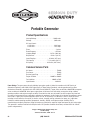
Specifications . . . . . . . . . . . . . . . . . . . . . . . . . . . . . . . . . 28
Product Specifications. . . . . . . . . . . . . . . . . . . . . . . . . . . . . . . . . . . . . . . . 28
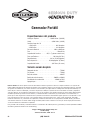
Common Service Parts . . . . . . . . . . . . . . . . . . . . . . . . . . . . . . . . . . . . . . . 28
3

Operator Safety
Equipment Description
Read this manual carefully and become familiar
with your generator. Know its applications, its
limitations and any hazards involved.
The generator is an engine–driven, revolving field, alternating
current (AC) generator. It was designed to supply electrical
power for operating compatible electrical lighting, appliances,
tools and motor loads. The generator’s revolving field is
driven at about 3,600 rpm by a single-cylinder engine.
NOTICE:
Exceeding generators wattage/amperage capacity
can damage generator and/or electrical devices connected to
it.
• DO NOT exceed the generator’s wattage/amperage capacity. See
Don’t Overload Generator in the Operation section.
Every effort has been made to ensure that the information in
this manual is both accurate and current. However, the
manufacturer reserves the right to change, alter or otherwise
improve the generator and this documentation at any time
without prior notice.
The Emission Control System for this generator is warranted
for standards set by the Environmental Protection Agency
and the California Air Resources Board.
Important Safety Information
The manufacturer cannot possibly anticipate every possible
circumstance that might involve a hazard. The warnings in
this manual, and the tags and decals affixed to the unit are,
therefore, not all-inclusive. If you use a procedure, work
method or operating technique that the manufacturer does
not specifically recommend, you must satisfy yourself that it
is safe for you and others. You must also make sure that the
procedure, work method or operating technique that you
choose does not render the generator unsafe.
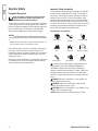
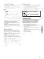
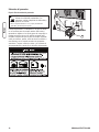
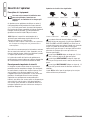
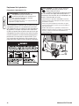
Safety Symbols and Meanings
The safety alert symbol indicates a potential personal
injury hazard. A signal word (DANGER, WARNING, or
CAUTION) is used with the alert symbol to designate a
degree or level of hazard seriousness. A safety symbol may
be used to represent the type of hazard. The signal word
NOTICE is used to address practices not related to personal
injury.
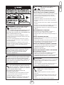
DANGER indicates a hazard which, if not avoided, will
result in death or serious injury.
WARNING indicates a hazard which, if not avoided,
could result in death or serious injury.
CAUTION indicates a hazard which, if not avoided, could
result in minor or moderate injury.
NOTICE address pratices not related to personal injury.
4 BRIGGSandSTRATTON.COM
Fire
Explosion
Toxic Fumes
Hot Surface
Moving Parts
Electrical Shock
Kickback
Flying Objects
Operator’s Manual

5
WARNING: Running engine gives off carbon
monoxide, an odorless, colorless, poison gas.
Breathing carbon monoxide can cause headache,
fatigue, dizziness, vomiting, confusion, seizures,
nausea, fainting or death.
• Operate generator ONLY outdoors.
• Install a battery operated carbon monoxide alarm near the
bedrooms.
• Keep exhaust gas from entering a confined area through
windows, doors, ventilation intakes, or other openings.
• DO NOT start or run engine indoors or in an enclosed area,
(even if windows and doors are open), including the generator
compartment of a recreational vehicle (RV).
WARNING: The engine exhaust from this product
contains chemicals known to the State of California to
cause cancer, birth defects, or other reproductive harm.
WARNING: Certain components in this product and
related accessories contain chemicals known to the State
of California to cause cancer, birth defects or other
reproductive harm. Wash hands after handling.
WARNING:
Generator produces hazardous voltage.
Failure to isolate generator from power utility can
result in death or injury to electric utility workers
due to backfeed of electrical energy.
• When using generator for backup power, notify utility company.
Use approved transfer equipment to isolate generator from
electric utility.
• Use a ground fault circuit interrupter (GFCI) in any damp or
highly conductive area, such as metal decking or steel work.
• DO NOT touch bare wires or receptacles.
• DO NOT use generator with electrical cords which are worn,
frayed, bare or otherwise damaged.
• DO NOT operate generator in the rain or wet weather.
• DO NOT handle generator or electrical cords while standing in
water, while barefoot, or while hands or feet are wet.
• DO NOT allow unqualified persons or children to operate or
service generator.
WARNING: Starter cord kickback (rapid retraction) can
result in bodily injury. Kickback will pull hand and
arm toward engine faster than you can let go.
Broken bones, fractures, bruises, or sprains
could result.
• When starting engine, pull cord slowly until resistance is felt
and then pull rapidly to avoid kickback.
• NEVER start or stop engine with electrical devices plugged in
and turned on.
WARNING: Fuel and its vapors are extremely
flammable and explosive.
Fire or explosion can cause severe burns
or death.
WHEN ADDING OR DRAINING FUEL
• Turn generator OFF and let it cool at least 2 minutes before
removing fuel cap. Loosen cap slowly to relieve pressure in
tank.
• Fill or drain fuel tank outdoors.
• DO NOT overfill tank. Allow space for fuel expansion.
• If fuel spills, wait until it evaporates before starting engine.
• Keep fuel away from sparks, open flames, pilot lights, heat, and
other ignition sources.
• DO NOT light a cigarette or smoke.
WHEN STARTING EQUIPMENT
• Ensure spark plug, muffler, fuel cap, and air cleaner are in place.
• DO NOT crank engine with spark plug removed.
WHEN OPERATING EQUIPMENT
• DO NOT tip engine or equipment at angle which causes fuel to
spill.
• This generator is not for use in mobile equipment or marine
applications.
WHEN TRANSPORTING OR REPAIRING EQUIPMENT
• Transport/repair with fuel tank EMPTY or with fuel shutoff valve
OFF.
• Disconnect spark plug wire.
WHEN STORING FUEL OR EQUIPMENT WITH FUEL IN TANK
• Store away from furnaces, stoves, water heaters, clothes
dryers, or other appliances that have pilot light or other ignition
source because they can ignite fuel vapors.
WARNING:
• This generator does not meet U. S. Coast Guard Regulation
33CFR-183 and should not be used on marine applications.
• Failure to use the appropriate U. S. Coast Guard approved
generator could result in death or serious injury and/or
property damage.

6 BRIGGSandSTRATTON.COM
NOTICE:
Exceeding generators wattage/amperage capacity
can damage generator and/or electrical devices connected to
it.
• DO NOT exceed the generator’s wattage/amperage capacity. See
Don’t Overload Generator in the Operation section.
• Start generator and let engine stabilize before connecting
electrical loads.
• Connect electrical loads in OFF position, then turn ON for
operation.
• Turn electrical loads OFF and disconnect from generator before
stopping generator.
NOTICE:
Improper treatment of generator can damage it
and shorten its life.
• Use generator only for intended uses.
• If you have questions about intended use, ask dealer or contact
local service center.
• Operate generator only on level surfaces.
• DO NOT expose generator to excessive moisture, dust, dirt, or
corrosive vapors.
• DO NOT insert any objects through cooling slots.
• If connected devices overheat, turn them off and disconnect them
from generator.
• Shut off generator if:
-electrical output is lost;
-equipment sparks, smokes, or emits flames;
-unit vibrates excessively.
WARNING: Contact with muffler area can result in
serious burns.
Exhaust heat/gases can ignite
combustibles, structures or damage
fuel tank causing a fire.
• DO NOT touch hot parts and AVOID hot exhaust gases.
• Allow equipment to cool before touching.
• Keep at least 5 feet (152 cm) of clearance on all sides of
generator including overhead.
• It is a violation of California Public Resource Code, Section
4442, to use or operate the engine on any forest-covered,
brush-covered, or grass-covered land unless the exhaust
system is equipped with a spark arrester, as defined in Section
4442, maintained in effective working order. Other states or
federal jurisdictions may have similar laws.
Contact the original equipment manufacturer, retailer, or dealer
to obtain a spark arrester designed for the exhaust system
installed on this engine.
• Replacement parts must be the same and installed in the same
position as the original parts.
WARNING: Unintentional sparking can result in fire or
electric shock.
WHEN ADJUSTING OR MAKING REPAIRS TO YOUR GENERATOR
• Disconnect the spark plug wire from the spark plug and place
the wire where it cannot contact spark plug.
WHEN TESTING FOR ENGINE SPARK
• Use approved spark plug tester.
• DO NOT check for spark with spark plug removed.
WARNING: Starter and other rotating parts can
entangle hands, hair, clothing, or accessories.
• NEVER operate generator without protective housing or covers.
• DO NOT wear loose clothing, jewelry or anything that may be
caught in the starter or other rotating parts.
• Tie up long hair and remove jewelry.
CAUTION:
Excessively high operating speeds increase
risk of injury and damage to generator.
Excessively low speeds impose a heavy load.
• DO NOT tamper with governed speed. Generator supplies
correct rated frequency and voltage when running at governed
speed.
• DO NOT modify generator in any way.

7
Assembly
Your generator requires some assembly and is ready for use
after it has been properly serviced with the recommended
fuel and oil.
If you have any problems with the assembly of your generator,
please call the generator helpline at (800) 743-4115. If calling
for assistance, please have the model, revision, and serial
number from the identification label available. See Controls
and Features for identification label location.
Unpack Generator
1. Set the carton on a rigid, flat surface.
2. Remove everything from carton except generator and
confirm all listed parts are present.
3. Open carton completely by cutting each corner from
top to bottom.
4. Leave generator on carton to install wheel kit.
The generator is supplied with:
• Operator’s manual
• Battery float charger
• Oil bottles
• Wheel kit
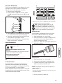
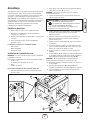
Install Wheel Kit
The wheel kit is designed to greatly improve the portability of
your generator.
NOTE: Wheel kit is not intended for over-the-road use.
You will need the following tools to install these
components:
• 13mm socket wrench
• 13mm open end wrench
• Pliers
• Safety glasses
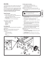
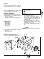
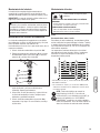
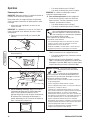
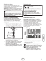
Install the wheel kit as follows:
1. Tip generator so that engine end is up.
2. Slide axle (A) through both mounting brackets.
3. Slide a wheel (B) over axle.
NOTE: Be sure to install wheel with raised hub inboard.
4. Place a washer (C) on axle and then place an e-ring (D)
in axle groove.
5. Install e-ring with pliers, squeezing from top of e-ring
to bottom of axle.
6. Repeat steps 3 through 5 to secure second wheel.
7. Tip generator so that engine side is down.
8. Line up holes in support leg (E) with holes in generator
frame.
9. Attach support leg using 2 capscrews (M8 x 20 mm)
(F) and 2 hex nuts (G). Tighten with a 13 mm socket
wrench and 13 mm wrench.
10. Repeat steps 8 and 9 to secure second support leg.
11. Attach handles (H) to brackets on generator frame as
shown, with 45 mm capscrews (J), flat washers (K),
nylon washers (L), and M8 lock nuts (M).
NOTE: DO NOT overtighten. Handles must be able to move
up and down freely.
12. Return generator to normal operating position (resting
on wheels and support leg).
13. Loop handle pins (N) on generator frame just above
handle brackets.
14. Raise handles and insert handle pins to move generator.
G
F
H
E
C
D
N
K
M
A
B
J
L
CAUTION:
E-rings can cause eye injury.
E-rings can spring back and become airborne
when installing or removing.
• Always wear eye protection when installing/removing e-rings.

Add Engine Oil
1. Place generator on a flat, level surface.
2. Clean area around oil fill and remove yellow oil fill cap.
NOTE: See Oil in Engine Maintenance to review oil
recommendations. Verify provided oil bottle is correct
viscosity for current ambient temperature.
3. Using oil funnel (optional), slowly pour contents of
provided oil bottle into oil fill opening until oil level
reaches the “Full” mark on the dipstick.
NOTICE:
Improper treatment of generator can damage it
and shorten its life.
• DO NOT attempt to crank or start the engine before it has been
properly serviced with the recommended oil. This may result in an
engine failure.
4. Replace oil fill cap and fully tighten.
Add Fuel
Fuel must meet these requirements:
• Clean, fresh, unleaded gasoline.
• A minimum of 87 octane/87 AKI (91 RON). High
altitude use, see High Altitude.
• Gasoline with up to 10% ethanol (gasohol) or up to
15% MTBE (methyl tertiary butyl ether) is acceptable.
NOTICE: Avoid generator damage.
Failure to follow Operator’s Manual for fuel
recommendations voids warranty.
• DO NOT use unapproved gasoline such as E85.
• DO NOT mix oil in gasoline.
• DO NOT modify engine to run on alternate fuels.
To protect the fuel system from gum formation, mix in a fuel
stabilizer when adding fuel. See Storage. All fuel is not the
same. If you experience starting or performance problems after
using fuel, switch to a different fuel provider or change brands.
This engine is certified to operate on gasoline. The emission
control system for this engine is EM (Engine Modifications).
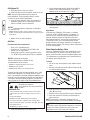
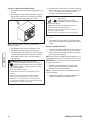
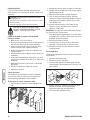
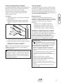
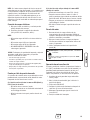
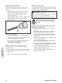
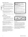
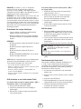
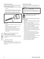
1. Clean area around fuel fill cap, remove cap.
2. Slowly add unleaded gasoline (A) to fuel tank (B). Be
careful not to fill above the baffle (C). This allows
adequate space for fuel expansion as shown.
3. Install fuel cap and let any spilled fuel evaporate before
starting engine.
High Altitude
At altitudes over 5,000 feet (1524 meters), a minimum
85 octane / 85 AKI (89 RON) gasoline is acceptable. To
remain emissions compliant, high altitude adjustment is
required. Operation without this adjustment will cause
decreased performance, increased fuel consumption, and
increased emissions. See an authorized dealer for high
altitude adjustment information. Operation of the engine at
altitudes below 2,500 feet (762 meters) with the high altitude
kit is not recommended.
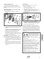
Attach Negative Battery Cable
Your unit is equipped with electric start capability but can be
started manually. If you choose not to use the electric start
feature, you do not need to connect the negative battery cable.
The sealed battery on the generator pre–installed except for
the negative (black) battery cable.
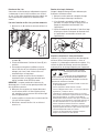
To install:
1. Cut off tie wrap securing loose end of negative (black)
cable.
2. Remove screw (A), lock washer (B) and flat washer (C)
on negative battery terminal.
3. Slide lock washer, flat washer and negative battery
cable (D) over screw.
4. Reattach screw to negative battery terminal and tighten.
5. Verify that connections to battery and generator are
tight and secure.
NOTE: If your battery is discharged, charge prior to use
following the instructions in the section Battery Float Charger.
8 BRIGGSandSTRATTON.COM
B
A
C
D
FUEL
TANK
C
B
A
WARNING: Fuel and its vapors are extremely
flammable and explosive.
Fire or explosion can cause severe burns
or death.
WHEN ADDING FUEL
• Turn generator OFF and let it cool at least 2 minutes before
removing fuel cap. Loosen cap slowly to relieve pressure in
tank.
• Fill fuel tank outdoors.
• DO NOT overfill tank. Allow space for fuel expansion.
• If fuel spills, wait until it evaporates before starting engine.
• Keep fuel away from sparks, open flames, pilot lights, heat, and
other ignition sources.
• DO NOT light a cigarette or smoke.
WARNING: Battery posts, terminals and related
accessories contain lead and lead compounds - chemicals
known to the State of California to cause cancer and
reproductive harm. Wash hands after handling.

9
System Ground
The generator has a system ground that connects the
generator frame components to the ground terminals on the
AC output receptacles. The system ground is connected to
the AC neutral wire (the neutral is bonded to the generator
frame).
Special Requirements
There may be Federal or State Occupational Safety and
Health Administration (OSHA) regulations, local codes, or
ordinances that apply to the intended use of the generator.
Please consult a qualified electrician, electrical inspector, or
the local agency having jurisdiction:
• In some areas, generators are required to be registered
with local utility companies.
• If the generator is used at a construction site, there
may be additional regulations which must be observed.
Connecting to a Building’s Electrical System
Connections for standby power to a building’s electrical
system must be made by a qualified electrician. The
connection must isolate the generator power from utility
power or other alternative power sources and must comply
with all applicable laws and electrical codes.
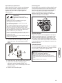
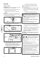
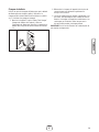
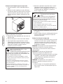
Generator Location
Clearances and Air Movement
Place generator outdoors in an area that will not accumulate
deadly exhaust gas. DO NOT place generator where exhaust
gas (A) could accumulate and enter inside or be drawn into a
potentially occupied building. Ensure exhaust gas is kept
away from any windows, doors, ventilation intakes, or other
openings that can allow exhaust gas to collect in a confined
area. Prevailing winds and air currents should be taken into
consideration when positioning generator.
A
WARNING:
Generator produces hazardous voltage.
Failure to isolate generator from power utility can
result in death or injury to electric utility workers
due to backfeed of electrical energy.
• When using generator for backup power, notify utility company.
Use approved transfer equipment to isolate generator from
electric utility.
• Use a ground fault circuit interrupter (GFCI) in any damp or
highly conductive area, such as metal decking or steel work.
• DO NOT touch bare wires or receptacles.
• DO NOT use generator with electrical cords which are worn,
frayed, bare or otherwise damaged.
• DO NOT operate generator in the rain or wet weather.
• DO NOT handle generator or electrical cords while standing in
water, while barefoot, or while hands or feet are wet.
• DO NOT allow unqualified persons or children to operate or
service generator.
WARNING: Exhaust heat/gases can ignite
combustibles, structures or damage fuel tank
causing a fire.
• Keep at least 5 ft. (152 cm) clearance on all sides of generator
including overhead.

10 BRIGGSandSTRATTON.COM
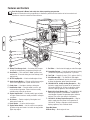
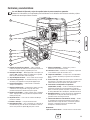
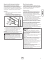
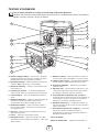
Features and Controls
Read this Operator’s Manual and safety rules before operating your generator.
Compare the illustrations with your generator, to familiarize yourself with the locations of various controls and
adjustments. Save this manual for future reference.
A - Battery Float Charger Jack — Use battery float charger
to keep the starting battery charged and ready for use.
B - Start Switch — Push and hold in “Start” position for a
maximum of 15 seconds during each start attempt, until
engine starts.
C - Oil Fill Cap/Dipstick — Check and add engine oil here.
D - Spark Arrester Muffler — Exhaust muffler lowers engine
noise and is equipped with a spark arrester screen.
E - Choke Lever — Used when starting a cold engine.
F - Identification Label — Provides model, revision, and
serial number of generator. Please have these readily
available when calling for assistance.
G - Engine Identification — Provides model, type and code
of engine. Please have these readily available if calling for
assistance.
H - Air Cleaner — Protects engine by filtering dust and
debris out of intake air.
J - Recoil Starter — Used to start the engine.
K - Engine Rocker Switch — Set this switch to run position
(I) before using recoil starter. Set switch to stop position
(O) to stop engine.
L - Fuel Valve — Used to turn fuel supply on and off to engine.
M - Grounding Fastener — Consult your local agency having
jurisdiction for grounding requirements in your area.
N - Fuel Tank — Capacity of seven (7) U.S. gallons (26.5 L).
P - Circuit Breakers (AC) — The 120 Volt AC, 20A duplex
receptacles are provided with "push to reset" circuit breakers
to protect the generator against electrical overload.
R - 120/240 Volt AC, 30 Amp Locking Receptacle — May
be used to supply electrical power for the operation of
120 and/or 240 Volt AC, 30 Amp, single phase, 60 Hz
electrical, lighting, appliance, tool and motor loads.
S - Double Pole Circuit Breaker (AC) — The 120/240 Volt AC,
30A locking receptacle is provided with a double pole
circuit breaker to protect the generator against electrical
overload. This switch also controls all receptacles.
T - 120 Volt AC, 20 Amp, Duplex Receptacles — May be
used to supply electrical power for the operation of
120 Volt AC, 20 Amp, single phase, 60 Hz electrical,
lighting, appliance, tool, and motor loads.
Items Not Shown:
Oil Drain Plug — Drain engine oil here.
A
B
D
E
K
T
J
S
P
N
H
C
M
F
L
G
R

11
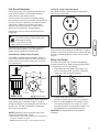
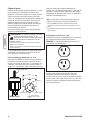
Cord Sets and Receptacles
Use only high quality, well-insulated, grounded extension
cords with the generator’s 120 Volt duplex receptacle.
Inspect extension cords before each use.
Check the ratings of all extension cords before you use
them. Extension cord sets used should be rated for 125 Volt
AC loads at 20 Amps or greater for most electrical devices.
Some devices, however, may not require this type of
extension cord. Check the operator’s manuals of those
devices for the manufacturer’s recommendations.
Keep extension cords as short as possible to minimize
voltage drop.
A double pole rocker switch circuit breaker is provided to
protect the locking receptacle. If this circuit breaker is
tripped, all panel receptacles are disconnected.
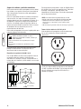
120/240 Volt AC, 30 Amp, Locking Receptacle
Use a NEMA L14-30 plug with this receptacle. Connect a
4-wire cord set rated for 250 Volt AC loads at 30 Amps (or
greater). You can use the same 4-wire cord if you plan to
run a 120 Volt load.
This receptacle powers 120/240 Volt AC, 60 Hz, single phase
loads requiring up to 7,200 watts of power (7.2 kW) at
30 Amps for 240 Volts or two independent 120 Volt loads at
30 Amps each. The outlet is protected by a double pole
rocker switch circuit breaker.
NOTICE:
Receptacles may be marked with rating value
greater than generator output capacity.
• NEVER attempt to power a device requiring more amperage than
generator or receptacle can supply.
• DO NOT overload the generator. See Don’t Overload Generator.
120 Volt AC, 20 Amp, Duplex Receptacles
Each duplex receptacle is protected against overload by a
push-to-reset circuit breaker.
Use each receptacle to operate 120 Volt AC, single-phase,
60 Hz electrical loads requiring up to 2,400 watts (2.4 kW) at
20 Amps of current. Use cord sets that are rated for 125 Volt
AC loads at 20 Amps (or greater). Inspect cord sets before
each use.
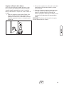
Battery Float Charger
Use battery float charger jack to keep the starting battery
charged and ready for use. Battery charging should be done
in a dry location, such as inside a garage.
1. Plug charger into unit’s “Battery Float Charger” jack,
which is located next to the start switch. Plug battery
charger into a 120 Volt AC wall receptacle.
2. Unplug charger from unit and wall outlet when
generator is being started and while it is in operation.
3. Keep this charger plugged in when generator is not in
use to prolong battery life. The charger has a built in
float equalizer and will not overcharge the battery, even
when plugged in for an extended period of time.
IMPORTANT: See Battery Maintenance for additional
information.
4-Wire Cord Set
240V
120V
120V
W (Neutral)
X (Hot)
Y (Hot)
NEMA L14-30
Ground (Green)
WARNING:
Overloaded electrical cords can overheat,
arc, and burn resulting in death, bodily injury,
and/or property damage.
• ONLY use cords rated for your loads.
• Follow all safeties on electrical cords.

12 BRIGGSandSTRATTON.COM
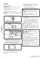
Operation
Starting the Engine
IMPORTANT: Always unplug the battery float charger before
starting the generator.
Disconnect all electrical loads from the generator. Use the
following start instructions:
1. Make sure unit is on a level surface.
IMPORTANT: Failure to start and operate the unit on a level
surface will cause the unit not to start or shut down during
operation.
2. Turn fuel valve (A) to “On” position.
3. Push engine rocker switch to run position (I).
4. Push choke lever (B) to “Choke” position.
5A. For electric starting, push and hold the start switch in
“Start” position until generator starts. To prolong the
life of starter components, DO NOT hold start switch in
“Start” position for more than 15 seconds, and pause
for at least 1 minute between starting attempts.
• If engine starts, proceed to step 7.
• If engine fails to start, proceed to step 6.
NOTE: If battery is discharged, use manual starting
instructions.
5B. For manual starting, grasp recoil handle and pull
slowly until slight resistance is felt. Then pull rapidly
one time only to start engine.
• If engine starts, proceed to step 7.
• If engine fails to start, proceed to step 6.
6. Move choke lever to “Half” choke position, and pull
recoil handle twice.
• If engine fails to start, repeat steps 5 thru 7.
7. Slowly move choke lever to “Run” position. If engine
falters, move choke lever to “Half” choke position until
engine runs smoothly, and then to “Run” position.
IMPORTANT: If engine floods, place choke lever in “Run”
position and crank until engine starts.
NOTE: If engine starts after 3 pulls but fails to run, or if unit
shuts down during operation, make sure unit is on a level
surface and check for proper oil level in crankcase. This unit
may be equipped with a low oil protection device. If so, oil
must be at proper level for engine to start.
A
B
WARNING: Starter cord kickback (rapid retraction) can
result in bodily injury. Kickback will pull hand and
arm toward engine faster than you can let go.
Broken bones, fractures, bruises, or sprains
could result.
• When starting engine, pull cord slowly until resistance is felt
and then pull rapidly to avoid kickback.
• NEVER start or stop engine with electrical devices plugged in
and turned on.
WARNING: Contact with muffler area can result in
serious burns.
Exhaust heat/gases can ignite
combustibles, structures or damage
fuel tank causing a fire.
• DO NOT touch hot parts and AVOID hot exhaust gases.
• Allow equipment to cool before touching.
• Keep at least 5 feet (152 cm) of clearance on all sides of
generator including overhead.
• It is a violation of California Public Resource Code, Section
4442, to use or operate the engine on any forest-covered,
brush-covered, or grass-covered land unless the exhaust
system is equipped with a spark arrester, as defined in Section
4442, maintained in effective working order. Other states or
federal jurisdictions may have similar laws.
Contact the original equipment manufacturer, retailer, or dealer
to obtain a spark arrester designed for the exhaust system
installed on this engine.
• Replacement parts must be the same and installed in the same
position as the original parts.

13
Connecting Electrical Loads
1. Let engine stabilize and warm up for a few minutes
after starting.
2. Plug in and turn on the desired 120 and/or 240 Volt AC,
single phase, 60 Hz electrical loads.
NOTE:
• DO NOT connect 240 Volt loads to the 120 Volt duplex
receptacles.
• DO NOT connect 3-phase loads to the generator.
• DO NOT connect 50 Hz loads to the generator.
• DO NOT OVERLOAD THE GENERATOR. See Don’t
Overload Generator.
NOTICE:
Exceeding generators wattage/amperage capacity
can damage generator and/or electrical devices connected to
it.
• DO NOT exceed the generator’s wattage/amperage capacity. See
Don’t Overload Generator in the Operation section.
• Start generator and let engine stabilize before connecting
electrical loads.
• Connect electrical loads in OFF position, then turn ON for
operation.
• Turn electrical loads OFF and disconnect from generator before
stopping generator.
Oil Pressure Shutdown
If engine oil pressure drops below a preset level, an oil
switch will stop the engine. Check oil level with dipstick.
If oil level is between ADD and FULL mark on dipstick:
1. DO NOT try to restart the engine.
2. Contact a Briggs & Stratton Authorized Dealer.
3. DO NOT operate engine until oil pressure is corrected.
If oil level is below ADD mark on dipstick:
1. Add oil to bring level to FULL mark.
2. Restart engine. If the engine stops again a low oil
pressure condition may still exist. DO NOT try to restart
the engine.
3. Contact a Briggs & Stratton Authorized Dealer.
4. DO NOT operate engine until oil pressure is corrected.
Stopping the Engine
1. Turn OFF and unplug all electrical loads from generator
panel receptacles. NEVER start or stop engine with
electrical devices plugged in and turned ON.
2. Let engine run at no-load for several minutes to
stabilize internal temperatures of engine and generator.
3. Push engine rocker switch to stop position (O).
4. Move fuel valve to “Off” position.
Cold Weather Operation
Under certain weather conditions (temperatures below 40°F
[4°C] combined with high humidity), your generator may
experience icing of the carburetor and/or the crankcase
breather system. To reduce this problem, you need to
perform the following:
1. Make sure generator has clean, fresh fuel.
2. Open fuel valve (turn valve to open position).
3. Use SAE 5W-30 oil.
4. Check oil level daily or after every eight (8) hours of
operation.
5. Maintain generator following Maintenance Schedule in
Maintenance section.
6. Shelter unit from elements.
WARNING:
Backfire, fire or engine damage could
occur.
• DO NOT stop engine by moving choke control to “Choke”
position
().

14 BRIGGSandSTRATTON.COM
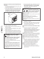
Creating a Temporary Cold Weather Shelter
1. For temporary shelter, the original shipping carton can
be used.
2. Cut off top carton flaps and one long side of carton to
expose muffler side of unit. If required, tape up other
sides of carton to fit over generator as shown.
NOTE: If required, remove wheel kit to fit carton over
generator as shown.
3. Cut appropriate slots to access receptacles of unit.
4. Face exposed end away from wind and elements.
5. Locate generator as described in the section Generator
Location. Keep exhaust gas from entering a confined
area through windows, doors, ventilation intakes or
other openings.
6. Start generator as described in the section Starting the
Engine, then place carton over generator. Keep at least
5 ft. (1.5 m) clearance on all sides of generator
including overhead with shelter in place.
7. Remove shelter when temperatures are above 40°F
[4°C].
8. Turn engine OFF and let cool two (2) minutes before
refueling. Let any spilled fuel evaporate before starting
engine.
Building a Cold Weather Shelter
1. Using non combustible material with a fire rating of at
least one hour, build a shelter that will enclose three
sides and the top of the generator. Make sure muffler
side of generator is exposed.
NOTE: Contact your local building material supplier for non
combustible materials with a fire rating of at least one hour.
IMPORTANT: Be sure shelter can easily be repositioned for
change in wind direction.
2. DO NOT enclose generator any more than shown.
Shelter should hold enough heat created by the
generator to prevent icing problem.
NOTE: If a wheel kit is installed on the generator, enlarge
shelter accordingly.
3. Follow steps 3 through 8 as described previously in
Creating a Temporary Cold Weather Shelter.
Wind
WARNING: Running engine gives off carbon
monoxide, an odorless, colorless, poison gas.
Breathing carbon monoxide can cause headache,
fatigue, dizziness, vomiting, confusion, seizures,
nausea, fainting or death.
• Operate generator ONLY outdoors.
• Install a battery operated carbon monoxide alarm near the
bedrooms.
• Keep exhaust gas from entering a confined area through
windows, doors, ventilation intakes, or other openings.
• DO NOT start or run engine indoors or in an enclosed area,
(even if windows and doors are open), including the generator
compartment of a recreational vehicle (RV).
WARNING: Contact with muffler area can result in
serious burns.
Exhaust heat/gases can ignite
combustibles, structures or damage
fuel tank causing a fire.
• DO NOT touch hot parts and AVOID hot exhaust gases.
• Allow equipment to cool before touching.
• Keep at least 5 feet (152 cm) of clearance on all sides of
generator including overhead.
• Remove shelter when temperatures are above 40°F [4°C].

15
Don’t Overload Generator
Capacity
You must make sure your generator can supply enough
rated (running) and surge (starting) watts for the items you
will power at the same time. Follow these simple steps:
1. Select the items you will power at the same time.
2. Total the rated (running) watts of these items. This is
the amount of power your generator must produce to
keep your items running. See Wattage Reference Guide.
3. Estimate how many surge (starting) watts you will need.
Surge wattage is the short burst of power needed to
start electric motor-driven tools or appliances such as a
circular saw or refrigerator. Because not all motors start
at the same time, total surge watts can be estimated by
adding only the item(s) with the highest additional surge
watts to the total rated watts from step 2.
Example:
Total Rated (Running) Watts = 3075
Highest Additional Surge Watts = 1800
Total Generator Output Required = 4875
Power Management
To prolong the life of your generator and attached devices, it
is important to take care when adding electrical loads to your
generator. There should be nothing connected to the
generator outlets before starting its engine. The correct and
safe way to manage generator power is to sequentially add
loads as follows:
1. With nothing connected to the generator, start the
engine as described in this manual.
2. Plug in and turn on the first load, preferably the largest
load you have.
3. Permit the generator output to stabilize (engine runs
smoothly and attached device operates properly).
4. Plug in and turn on the next load.
5. Again, permit the generator to stabilize.
6. Repeat steps 4 and 5 for each additional load.
NEVER add more loads than the generator capacity. Take
special care to consider surge loads in generator capacity, as
described above.
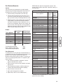
* Wattages listed are approximate only. Check tool or
appliance for actual wattage.
Tool or Appliance
Rated (Running)
Watts
Additional Surge
(Starting) Watts
Window Air
Conditioner
1200 1800
Refrigerator 800 1600
Deep Freezer 500 500
Television 500 —
Light (75 Watts) 75 —
3075 Total
Running Watts
1800 Highest
Surge Watts
Wattage Reference Guide
Tool or Appliance
Rated*
(Running)
Watts
Additional
Surge
(Starting)
Watts
Essentials
Light Bulb - 75 watt 75 —
Deep Freezer 500 500
Sump Pump 800 1200
Refrigerator/Freezer - 18 cf 800 1600
Water Well Pump - 1/3 hp 1000 2000
Heating/Cooling
Window AC - 10,000 BTU 1200 1800
Window Fan 300 600
Furnace Fan Blower - 1/2 hp 800 1300
Kitchen
Microwave Oven - 1000 Watt 1000 —
Coffee Maker 1500 —
Electric Stove - Single Element 1500 —
Hot Plate 2500 —
Family Room
DVD/CD Player 100 —
VCR 100 —
Stereo Receiver 450 —
Color Television - 27 in 500 —
Personal Computer w/17 in
monitor
800 —
Other
Security System 180 —
AM/FM Clock Radio 300 —
Garage Door Opener - 1/2 hp 480 520
Electric Water Heater - 40 gallon 4000 —
DIY/Job Site
Quartz Halogen Work Light 1000 —
Airless Sprayer - 1/3 hp 600 1200
Reciprocating Saw 960 960
Electric Drill - 1/2 hp 1000 1000
Circular Saw - 7-1/4 in 1500 1500
Miter Saw - 10 in 1800 1800
Table Planer - 6 in 1800 1800
Table Saw/Radial Arm Saw - 10 in 2000 2000
Air Compressor - 1-1/2 hp 2500 2500

16 BRIGGSandSTRATTON.COM
Maintenance
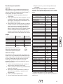
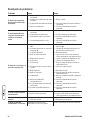
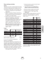
Maintenance Schedule
Follow the hourly or calendar intervals, whichever occurs
first. More frequent service is required when operating in
adverse conditions noted below.
1
Service more often under dirty or dusty conditions.
General Recommendations
Regular maintenance will improve the performance and
extend the life of the generator. See an authorized dealer for
service.
The generator’s warranty does not cover items that have
been subjected to operator abuse or negligence. To receive
full value from the warranty, the operator must maintain the
generator as instructed in this manual.
Some adjustments will need to be made periodically to
properly maintain your generator.
All service and adjustments should be made at least once
each season. Follow the requirements in the Maintenance
Schedule chart above.
NOTE: Once a year you should clean or replace the spark
plug and replace the air filter. A new spark plug and clean air
filter assure proper fuel-air mixture and help your engine run
better and last longer.
Emissions Control
Maintenance, replacement, or repair of the emissions
control devices and systems may be performed by any
non-road engine repair establishment or individual.
However, to obtain ”no charge” emissions control service,
the work must be performed by a factory authorized dealer.
See the Emissions Warranty.
Generator Maintenance
Generator maintenance consists of keeping the unit clean
and dry. Operate and store the unit in a clean dry
environment where it will not be exposed to excessive dust,
dirt, moisture, or any corrosive vapors. Cooling air slots in
the generator must not become clogged with snow, leaves,
or any other foreign material.
NOTE: DO NOT use water or other liquids to clean generator.
Liquids can enter engine fuel system, causing poor
performance and/or failure to occur. In addition, if liquid
enters generator through cooling air slots, some of the liquid
will be retained in voids and cracks of the rotor and stator
winding insulation. Liquid and dirt buildup on the generator
internal windings will eventually decrease the insulation
resistance of these windings.
Cleaning
Daily or before use, look around and underneath the
generator for signs of oil or fuel leaks. Clean accumulated
debris from inside and outside the generator. Keep the
linkage, spring and other engine controls clean. Inspect
cooling air slots and openings on generator. These openings
must be kept clean and unobstructed.
Engine parts should be kept clean to reduce the risk of
overheating and ignition of accumulated debris:
• Use a damp cloth to wipe exterior surfaces clean.
NOTICE:
Improper treatment of generator can damage it
and shorten its life.
• DO NOT expose generator to excessive moisture, dust, dirt, or
corrosive vapors.
• DO NOT insert any objects through cooling slots.
• Use a soft bristle brush to loosen caked on dirt or oil.
• Use a vacuum cleaner to pick up loose dirt and debris.
Battery Maintenance
Other than float charging, described elsewhere, no
maintenance is required for the starting battery. Keep the
battery and terminals clean and dry.
IMPORTANT: Battery charging should be performed in a dry
location, such as inside a garage.
First 5 Hours
• Change engine oil
Every 8 Hours or Daily
• Clean debris
• Check engine oil level
Every 25 Hours or Yearly
• Service engine air cleaner pre-filter
1
Every 50 Hours or Yearly
• Change engine oil
1
Every 100 Hours or Yearly
• Service air cleaner paper filter
1
• Service fuel filter
• Service spark plug
• Inspect muffler and spark arrester
• Clean cooling system
1
Every 250 Hours or Yearly
• Check valve clearance
WARNING: Battery posts, terminals and related
accessories contain lead and lead compounds - chemicals
known to the State of California to cause cancer and
reproductive harm. Wash hands after handling.

17
Fuel Valve Maintenance
The fuel valve is equipped with a fuel sediment cup, screen,
retaining ring and o-ring that need to be cleaned every
100 hours or once a year (whichever occurs first).
1. Move fuel valve to “Off” position.
2. Remove sediment cup (A) from fuel valve. Remove
o-ring (B), retaining ring (C) and screen (D) from fuel
valve.
3. Wash sediment cup, o-ring, retaining ring, and screen
in a nonflammable solvent. Dry them thoroughly.
4. Place screen, retaining ring, and o-ring into fuel valve.
Install sediment cup and tighten securely.
5. Move fuel valve to “On” position, and check for leaks.
Replace o-ring if there is any leakage.
Engine Maintenance
Oil
Oil Recommendations
We recommend the use of Briggs & Stratton Warranty
Certified oils for best performance. Other high-quality
detergent oils are acceptable if classified for service SF, SG,
SH, SJ or higher. DO NOT use special additives.
Outdoor temperatures determine the proper oil viscosity for
the engine. Use the chart to select the best viscosity for the
outdoor temperature range expected.
* Below 40°F (4°C) the use of SAE 30 will result in hard starting.
** Above 80°F (27°C) the use of 10W30 may cause increased oil
consumption. Check oil level more frequently.
NOTE: Synthetic oil meeting ILSAC GF-2, API
certification mark and API service symbol with
“SJ/CF ENERGY CONSERVING” or higher, is an
acceptable oil at all temperatures. Use of synthetic
oil does not alter required oil change intervals.
Checking Oil Level
Oil level should be checked prior to each use or at least
every 8 hours of operation. Keep oil level maintained.
1. Make sure generator is on a level surface.
2. Clean area around oil fill, remove oil cap/dipstick and
wipe dipstick with clean cloth. Replace dipstick.
Remove and and check oil level.
3. Verify oil is at “Full” mark (A) on dipstick. Replace and
tighten oil cap/dipstick.
Adding Engine Oil
1. Make sure generator is on a level surface.
2. Check oil level as described in Checking Oil Level.
3. If needed, slowly pour oil into oil fill opening to the
“Full” mark on dipstick. DO NOT overfill.
NOTICE: Overfilling with oil may cause the engine to not
start, or hard starting.
• DO NOT overfill.
• If over the FULL mark on dipstick, drain oil to reduce oil level to
FULL mark on dipstick.
4. Replace and tighten oil cap/dipstick.
A
B
C
D
WARNING: Unintentional sparking can result in fire or
electric shock.
WHEN ADJUSTING OR MAKING REPAIRS TO YOUR
GENERATOR
• Disconnect the spark plug wire from the spark plug and place
the wire where it cannot contact spark plug.
WHEN TESTING FOR ENGINE SPARK
• Use approved spark plug tester.
• DO NOT check for spark with spark plug removed.
A

18 BRIGGSandSTRATTON.COM
Changing Engine Oil
If you are using your generator under extremely dirty or
dusty conditions, or in extremely hot weather, change the oil
more often.
KEEP OUT OF REACH OF CHILDREN. DON’T
POLLUTE. CONSERVE RESOURCES. RETURN
USED OIL TO COLLECTION CENTERS.
Change the oil while the engine is still warm from
running, as follows:
1. Make sure unit is on a level surface.
2. Disconnect the spark plug wire from the spark plug and
place the wire where it cannot contact spark plug.
3. Clean area around oil drain plug. The oil drain plug is
located at base of engine, opposite carburetor.
4. Remove oil drain plug and drain oil completely into a
suitable container.
5. Reinstall oil drain plug and tighten securely. Remove oil
cap/dipstick.
6. Slowly pour recommended oil (about 32 oz.) into oil fill
opening. Pause to permit oil to settle. Fill to “Full” mark
on dipstick.
7. Wipe dipstick clean each time oil level is checked. DO
NOT overfill.
8. Reinstall oil cap/dipstick. Tighten cap securely.
9. Wipe up any spilled oil.
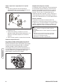
Service Air Cleaner
Your engine will not run properly and may be damaged if
you run it with a dirty air cleaner. Clean or replace more
often if operating under dusty or dirty conditions.
To service the air cleaner, follow these steps:
1. Loosen knobs and swing air cleaner cover (A) to the
side.
2. Remove cover and air cleaner assembly from base (B).
3. Carefully remove cartridge retainer (C) and pre-cleaner
(D) from paper filter (E).
4. Wipe clean inside of base and cover thoroughly.
5. Clean or replace the foam pre-cleaner. Wash pre-
cleaner in a solution of household detergent and warm
water, then rinse thoroughly. Squeeze dry in a clean
cloth. DO NOT twist.
6. Saturate foam pre-cleaner in clean engine oil and
squeeze in a clean, absorbent cloth to remove all
excess oil. DO NOT twist.
IMPORTANT: The engine will smoke during initial start-up if
too much oil is left in the pre-cleaner.
7. Clean paper filter by tapping it gently on a solid surface.
If the paper filter is too dirty, replace it with a new one.
Dispose of the old filter properly.
8. Reinstall pre-cleaner on retainer.
9. Install pre-cleaner in cover with mesh side toward
paper filter. Install paper filter in cover or on base.
10. Assemble air cleaner assembly and cover onto base
and tighten knobs.
Service Spark Plug
Changing the spark plug will help your engine to start easier
and run better.
1. Clean area around spark plug.
2. Remove and inspect spark plug.
3. Check electrode gap with wire feeler gauge and reset
spark plug gap to recommended gap if necessary (see
Specifications).
4. Replace spark plug if electrodes are pitted, burned or
porcelain is cracked. Use the recommended
replacement spark plug. See Specifications.
5. Install spark plug and tighten firmly.
CAUTION: Avoid prolonged or repeated skin contact
with used motor oil.
• Used motor oil has been shown to cause skin cancer in certain
laboratory animals.
• Thoroughly wash exposed areas with soap and water.
E
B
C
D
A

19
Inspect Muffler and Spark Arrester
Inspect the muffler for cracks, corrosion, or other damage.
Remove the spark arrester, if equipped, and inspect for
damage or carbon blockage. If replacement parts are
required, make sure to use only original equipement
replacement parts.
Clean and inspect the spark arrester as follows:
1. To remove muffler heat shield (A) from muffler (B),
remove four screws that connect guard to muffler
bracket.
2. Remove four screws that attach spark arrester screen (C).
3. Inspect screen and obtain a replacement if torn,
perforated or otherwise damaged. DO NOT use a
defective screen. If screen is not damaged, clean it with
commercial solvent.
4. Reattach screen and muffler guard.
Air Cooling System
Over time debris may accumulate in cylinder cooling fins and
cannot be observed without partial engine disassembly. For
this reason, we recommend you have an authorized service
dealer clean the cooling system (D) per recommended
intervals (see Maintenance Schedule in beginning of
Maintenance section). Equally important is to keep top of
engine free from debris. See Clean Debris.
Check Valve Clearance
Regular valve clearance check and adjustment will improve
performance and extend engine life. This procedure cannot
be done without partial engine disassembly and the use of
special tools. For this reason we recommend that you have
an authorized service dealer check and adjust valve clearance
at recommended intervals (see Maintenance Schedule in the
Maintenance section).
Carburetor Adjustment
The carburetor on this engine is low emission. It is equipped
with a non-adjustable idle mixture valve. Top speed has been
set at the factory. If adjustment is required, see an
authorized service dealer.
A
B
C
D
WARNING: Contact with muffler area can result in
serious burns.
Exhaust heat/gases can ignite
combustibles, structures or damage
fuel tank causing a fire.
• DO NOT touch hot parts and AVOID hot exhaust gases.
• Allow equipment to cool before touching.
• Keep at least 5 feet (152 cm) of clearance on all sides of
generator including overhead.
• It is a violation of California Public Resource Code, Section
4442, to use or operate the engine on any forest-covered,
brush-covered, or grass-covered land unless the exhaust
system is equipped with a spark arrester, as defined in Section
4442, maintained in effective working order. Other states or
federal jurisdictions may have similar laws.
Contact the original equipment manufacturer, retailer, or dealer
to obtain a spark arrester designed for the exhaust system
installed on this engine.
• Replacement parts must be the same and installed in the same
position as the original parts.
CAUTION:
Excessively high operating speeds increase
risk of injury and damage to generator.
Excessively low speeds impose a heavy load.
• DO NOT tamper with governed speed. Generator supplies
correct rated frequency and voltage when running at governed
speed.
• DO NOT modify generator in any way.

20 BRIGGSandSTRATTON.COM
Storage
The generator should be started at least once every seven
days and allowed to run at least 30 minutes. If this cannot be
done and you must store the unit for more than 30 days, use
the following guidelines to prepare it for storage.
Generator Storage
• Clean the generator as outlined in Cleaning.
• Check that cooling air slots and openings on generator
are open and unobstructed.
Long Term Storage Instructions
Fuel can become stale when stored over 30 days. Stale fuel
causes acid and gum deposits to form in the fuel system or
on essential carburetor parts. To keep fuel fresh, use Briggs
& Stratton FRESH START® fuel stabilizer, available as a
liquid additive or a drip concentrate cartridge.
There is no need to drain gasoline from the engine if a fuel
stabilizer is added according to instructions. Run the engine
for 2 minutes to circulate the stabilizer throughout the fuel
system. The engine and fuel can then be stored up to
24 months.
If gasoline in the engine has not been treated with a fuel
stabilizer, it must be drained into an approved container. Run
the engine until it stops from lack of fuel. The use of a fuel
stabilizer in the storage container is recommended to
maintain freshness.
Change Oil
While engine is still warm, drain oil from crankcase. Refill
with recommended grade. See Changing Engine Oil.
Other Storage Tips
1. DO NOT store fuel from one season to another unless it
has been treated as described in Long Term Storage
Instructions.
2. Replace fuel container if it starts to rust. Rust and/or
dirt in fuel can cause problems if it’s used with this
unit.
3. Cover unit with a suitable protective cover that does not
retain moisture.
4. Store generator in clean, dry area.
WARNING: Fuel and its vapors are extremely
flammable and explosive.
Fire or explosion can cause severe burns
or death.
WHEN STORING FUEL OR EQUIPMENT WITH FUEL IN TANK
• Store away from furnaces, stoves, water heaters, clothes dryers
or other appliances that have pilot light or other ignition source
because they can ignite fuel vapors.
WHEN DRAINING FUEL
• Turn generator OFF and let it cool at least 2 minutes before
removing fuel cap. Loosen cap slowly to relieve pressure in
tank.
• Drain fuel tank outdoors.
• Keep fuel away from sparks, open flames, pilot lights, heat, and
other ignition sources.
• DO NOT light a cigarette or smoke.
WARNING:
Storage covers can be flammable.
• DO NOT place a storage cover over a hot generator.
• Let equipment cool for a sufficient time before placing the cover
on the equipment.
La page est en cours de chargement...
La page est en cours de chargement...
La page est en cours de chargement...
La page est en cours de chargement...
La page est en cours de chargement...
La page est en cours de chargement...
La page est en cours de chargement...
La page est en cours de chargement...
La page est en cours de chargement...
La page est en cours de chargement...
La page est en cours de chargement...
La page est en cours de chargement...
La page est en cours de chargement...
La page est en cours de chargement...
La page est en cours de chargement...
La page est en cours de chargement...
La page est en cours de chargement...
La page est en cours de chargement...
La page est en cours de chargement...
La page est en cours de chargement...
La page est en cours de chargement...
La page est en cours de chargement...
La page est en cours de chargement...
La page est en cours de chargement...
La page est en cours de chargement...
La page est en cours de chargement...
La page est en cours de chargement...
La page est en cours de chargement...
La page est en cours de chargement...
La page est en cours de chargement...
La page est en cours de chargement...
La page est en cours de chargement...
La page est en cours de chargement...
La page est en cours de chargement...
La page est en cours de chargement...
La page est en cours de chargement...
La page est en cours de chargement...
La page est en cours de chargement...
La page est en cours de chargement...
La page est en cours de chargement...
La page est en cours de chargement...
La page est en cours de chargement...
La page est en cours de chargement...
La page est en cours de chargement...
La page est en cours de chargement...
La page est en cours de chargement...
La page est en cours de chargement...
La page est en cours de chargement...
La page est en cours de chargement...
La page est en cours de chargement...
La page est en cours de chargement...
La page est en cours de chargement...
La page est en cours de chargement...
La page est en cours de chargement...
La page est en cours de chargement...
La page est en cours de chargement...
La page est en cours de chargement...
La page est en cours de chargement...
La page est en cours de chargement...
La page est en cours de chargement...
La page est en cours de chargement...
La page est en cours de chargement...
La page est en cours de chargement...
La page est en cours de chargement...
-
 1
1
-
 2
2
-
 3
3
-
 4
4
-
 5
5
-
 6
6
-
 7
7
-
 8
8
-
 9
9
-
 10
10
-
 11
11
-
 12
12
-
 13
13
-
 14
14
-
 15
15
-
 16
16
-
 17
17
-
 18
18
-
 19
19
-
 20
20
-
 21
21
-
 22
22
-
 23
23
-
 24
24
-
 25
25
-
 26
26
-
 27
27
-
 28
28
-
 29
29
-
 30
30
-
 31
31
-
 32
32
-
 33
33
-
 34
34
-
 35
35
-
 36
36
-
 37
37
-
 38
38
-
 39
39
-
 40
40
-
 41
41
-
 42
42
-
 43
43
-
 44
44
-
 45
45
-
 46
46
-
 47
47
-
 48
48
-
 49
49
-
 50
50
-
 51
51
-
 52
52
-
 53
53
-
 54
54
-
 55
55
-
 56
56
-
 57
57
-
 58
58
-
 59
59
-
 60
60
-
 61
61
-
 62
62
-
 63
63
-
 64
64
-
 65
65
-
 66
66
-
 67
67
-
 68
68
-
 69
69
-
 70
70
-
 71
71
-
 72
72
-
 73
73
-
 74
74
-
 75
75
-
 76
76
-
 77
77
-
 78
78
-
 79
79
-
 80
80
-
 81
81
-
 82
82
-
 83
83
-
 84
84


Simplicity 030334-0 Manuel utilisateur
- Catégorie
- Groupes électrogènes
- Taper
- Manuel utilisateur
dans d''autres langues
- English: Simplicity 030334-0 User manual
- español: Simplicity 030334-0 Manual de usuario
Documents connexes
-
Simplicity 030470-02 Manuel utilisateur
-
-
Briggs & Stratton 030439-0 Manuel utilisateur
-
-
Simplicity 030471-00 Manuel utilisateur
-
Simplicity 030664-00 Manuel utilisateur
-
Briggs & Stratton PRO10000 Manuel utilisateur
-
-
-