
Ceiling Hoods
HBC1 Series
INSTALLATION,
USE & CARE INSTRUCTIONS
Serial number:
1105483D
BEST 550 Lemire Blvd., Drummondville, Québec, Canada J2C 7W9 BestRangeHoods.ca 800-567-3855
BEST 926 West State Street, Hartford, Wisconsin, USA 53027 BestRangeHoods.com 800-558-1711

INSTALLATION, USE & CARE INSTRUCTIONS
SAFETY
INSTALLATION, USE & CARE INSTRUCTIONS
TABLE OF CONTENTS
22
Safety . . . . . . . . . . . . . . . . . . . . . . . . . . . . . . . . . . . . . . . . . . . . . . . . . . . . . 3-4
Installation . . . . . . . . . . . . . . . . . . . . . . . . . . . . . . . . . . . . . . . . . . . . . . . . . 5-11
Recommended Tools and Accessories . . . . . . . . . . . . . . . . . . . . . . . . . . . . . . . . . . . . . 5
Hood Specifications . . . . . . . . . . . . . . . . . . . . . . . . . . . . . . . . . . . . . . . . . . . . . . . . . . .5
Install the Ductwork . . . . . . . . . . . . . . . . . . . . . . . . . . . . . . . . . . . . . . . . . . . . . . . . . . 6
Blower Outlet Position . . . . . . . . . . . . . . . . . . . . . . . . . . . . . . . . . . . . . . . . . . . . . . . . .6
Prepare the Ceiling Opening and the Hood Support . . . . . . . . . . . . . . . . . . . . . . . . . . . .7
Install the Hood . . . . . . . . . . . . . . . . . . . . . . . . . . . . . . . . . . . . . . . . . . . . . . . . . . . . . .8
Prepare the Hood for Wiring Connection and Blower Installation . . . . . . . . . . . . . . . . . . .8
Wiring . . . . . . . . . . . . . . . . . . . . . . . . . . . . . . . . . . . . . . . . . . . . . . . . . . . . . . . . . . . . .9
Blower Installation . . . . . . . . . . . . . . . . . . . . . . . . . . . . . . . . . . . . . . . . . . . . . . . . 10-11
External Blower Programming Procedure . . . . . . . . . . . . . . . . . . . . . . . . . . . . . . . . . .11
Operation . . . . . . . . . . . . . . . . . . . . . . . . . . . . . . . . . . . . . . . . . . . . . . . . . . .12
Maintenance and Cleaning . . . . . . . . . . . . . . . . . . . . . . . . . . . . . . . . . . . . . .13
Grease Filters
Stainless Steel Cleaning
Service Parts . . . . . . . . . . . . . . . . . . . . . . . . . . . . . . . . . . . . . . . . . . . . . . . . .14
Warranty . . . . . . . . . . . . . . . . . . . . . . . . . . . . . . . . . . . . . . . . . . . . . . . . . . . .15

INSTALLATION, USE & CARE INSTRUCTIONS
SAFETY
3
To register your product, please visit our website:
In the United States - BestRangeHoods.com
In Canada - BestRangeHoods.ca
For Technical Support, call:
In the United States - 800-558-1711
In Canada - 800-567-3855
Installer: Leave this manual with the homeowner.
READ AND SAVE THESE INSTRUCTIONS
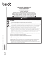
Intended for domestic cooking only !!
! WARNING
TO REDUCE THE RISK OF FIRE, ELECTRIC SHOCK, OR INJURY TO PERSONS, OBSERVE THE
FOLLOWING:
• Use this unit only in the manner intended by the manufacturer. If you have questions, contact the
manufacturer at the address or telephone number listed in the warranty.
• Before servicing or cleaning unit, switch power off at service panel and lock the service disconnecting
means to prevent power from being switched on accidentally. When the service disconnecting means
cannot be locked, securely fasten a prominent warning device, such as a tag, to the service panel.
• Installation work and electrical wiring must be done by qualified person(s) in accordance with all
applicable codes and standards, including fire-rated construction codes and standards.
• Sufficient air is needed for proper combustion and exhausting of gases through the flue (chimney)
of fuel burning equipment to prevent backdrafting. Follow the heating equipment manufacturer’s
guidelines and safety standards such as those published by the National Fire Protection Association
(NFPA), and the American Society for Heating, Refrigeration and Air Conditioning Engineers
(ASHRAE), and the local code authorities.
• When cutting or drilling into wall or ceiling, do not damage electrical wiring and other hidden utilities.
• Ducted fans must always be vented to the outdoors.
• Do not use this unit with any separate solid-state speed control device.
• To reduce the risk of fire, use only metal ductwork.
• This unit must be grounded.
• When installing, servicing or cleaning the unit, it is recommended to wear safety glasses and gloves.
• When applicable local regulations comprise more restrictive installation and/or certification
requirements, the aforementioned requirements prevail on those of this document and the installer
agrees to conform to these at his own expense.

INSTALLATION, USE & CARE INSTRUCTIONS
SAFETY
4
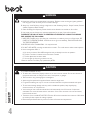
! WARNING
TO REDUCE THE RISK OF A RANGE TOP GREASE FIRE:
A. Never leave surface units unattended at high settings. Boilovers cause smoking and greasy spillovers
that may ignite. Heat oils slowly on low or medium settings.
B. Always turn hood ON when cooking at high heat or when flambeing food (i.e. Crepes Suzette, Cherries
Jubilee, Peppercorn Beef Flambé).
C. Clean ventilating fans frequently. Grease should not be allowed to accumulate on fan or filter.
D. Use proper pan size. Always use cookware appropriate for the size of the surface element.
TO REDUCE THE RISK OF INJURY TO PERSONS IN THE EVENT OF A RANGE TOP GREASE
FIRE, OBSERVE THE FOLLOWING:*
1. SMOTHER FLAMES with a close-fitting lid, cookie sheet, or metal tray, then turn off the burner. BE
CAREFUL TO PREVENT BURNS. If the flames do not go out immediately, EVACUATE AND CALL
THE FIRE DEPARTMENT.
2. NEVER PICK UP A FLAMING PAN - You may be burned.
3. DO NOT USE WATER, including wet dishcloths or towels - This could cause a violent steam explosion.
4. Use an extinguisher ONLY if:
A. You know you have a Class ABC extinguisher and you already know how to operate it.
B. The fire is small and contained in the area where it started.
C. The fire department has been called.
D. You can fight the fire with your back to an exit.
* Based on “Kitchen Fire Safety Tips” published by NFPA.
! CAUTION
!• For indoor residential use only.
• To reduce risk of fire and to properly exhaust air, be sure to duct air outside. Do not vent exhaust air
into spaces within walls or ceilings or into attics, crawl spaces, or garages.
• Take care when using cleaning agents or detergents.
• Avoid using food products that produce flames under the range hood.
• For general ventilating use only. Do not use to exhaust hazardous or explosive materials and vapors.
• To avoid motor bearing damage and noisy and/or unbalanced impellers, keep drywall spray,
construction dust, etc. off power unit.
• Your hood motor has a thermal overload which will automatically shut off the motor if it becomes
overheated. The motor will restart when it cools down. If the motor continues to shut off and restart,
have the hood serviced.
• The bottom of the hood MUST NOT BE LESS than 48" and recommended at a maximum of 84" above
the cooktop for best capture of cooking impurities.
• Please read specification label on product for further information and requirements.

INSTALLATION, USE & CARE INSTRUCTIONS
INSTALLATION
5
RECOMMENDED TOOLS AND ACCESSORIES
• Measuring tape
• Phillips screwdriver no. 2
• Nut driver or socket 3/8”
• Flat blade screwdriver (to open knockout holes)
• Saw
• Sheet metal shears
• Pliers
• Metal foil duct tape
• Scissors (to cut metal foil duct tape)
• Pencil
• Wire stripper
• Strain relief(s), 7/8” diameter (one to secure house
wiring cable to the hood and another one to secure
external blower cable to the hood)
• Drill and 1/8” drill bit
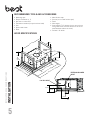
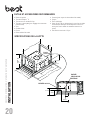
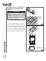
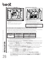
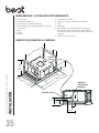
HOOD SPECIFICATIONS
43-
5
/1
6 | 63-1/2
27-9
/1
6
2-5/8
Min:
14
Max:
23-3/4
5-1/2
35-9/16
C/L
C/L
C/L
25-3
/1
6
41 |
61-
1/4
23-
1
1/
16
1-3/16
8-3/8
C/L
4-5/8
8-1/16
4-1/8
8-3/16
120 VAC INPUT
EXTERNAL BLOWER
INPUT
Electrical
input

INSTALLATION, USE & CARE INSTRUCTIONS
INSTALLATION
6
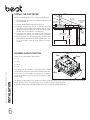
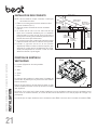
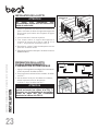
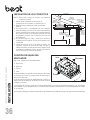
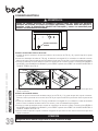
INSTALL THE DUCTWORK
NOTE: To reduce the risk of fire, use only metal ductwork.
1. Decide where the ductwork will run between the insert and
the outside (FIG. 1).
2. Choose desired blower outlet position (FIG. 2).
3. A straight, short duct run using 8" round damper (included
with blower kit) for single internal blower and 10" round
damper (included with the hood) for all other blower types
will allow the hood to perform most efficiently.
4. Long duct runs, elbows and transitions will reduce the
performance of the hood. Use as few of them as possible.
5. Install wall cap or roof cap (sold separately). Connect metal
ductwork to cap and work back towards the hood location. Use
2” foil duct tape to seal the joints between ductwork
sections.
FIG. 1
ROOF CAP
8" OR 10"
ROUND DUCT
48" TO 84" ABOVE
COOKING SURFACE
HOOD
8" OR 10"
ROUND DUCT
8" OR 10" ROUND
TO 3¼" X14"
REDUCER
84" ABOVE
THE FLOOR
MINIMUM
3¼" X14"
UNDER
EAVE
VENT
BLOWER OUTLET POSITION
There are four (4) possible outlet positions:
• Top
• Front
• Back
• Side
The damper can be installed on the housing prior to install
the hood in the ceiling with Side and Top outlet positions only.
In the case of Front and Back outlet positions, the damper
has to be installed on the housing once the hood is installed
in the ceiling. FIG. 2
TOP
FRONT
BACK
SIDE
10" damper included with the hood needs to be used for all exterior blower setup and internal blower PM12. With external
blower, ducting is to be connected directly on the damper (no rough-in plate required).
8" damper is needed only with PM6 internal blower. It is included in the PM6 blower kit.

INSTALLATION, USE & CARE INSTRUCTIONS
INSTALLATION
7
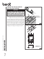
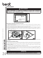
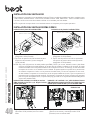
PREPARE THE CEILING OPENING
AND THE HOOD SUPPORT
CAUTION
Ducting through side/front/back may have
restrictions. Please take support frame
into consideration and leave enough space
between support frame and the ducting
chosen. Refer to Hood Specifications section
for hood dimensions and ducting position.
NOTE: Support frame shown in this document is only an
example. Follow local building code as required.
The hood should always be centered over the cooktop. Make
sure there is adequate space in the ceiling structure to install
the hood and ductwork. The bottom of the hood MUST NOT
BE LESS than 48" and recommended at a maximum of 84"
above the cooktop for best capture of cooking impurities.
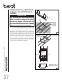
Construct a wood framing suitable for your installation (ex.
shown in FIG.3 and 4). Refer to Hood Specifications section
at page 5 for more details. The structure must be capable of
supporting its own weight plus the weight of the hood.
min 14"
max 23-3/4"
DOUBLE
HEADERS
A
B
MODEL HBC143:
A = 25 ¾", B = 41 ½"
MODEL HBC163:
A = 25 ¾", B = 61 ¾"
FIG. 3
MODEL HBC143: 95 LB
MODEL HBC163: 120 LB
FIG. 4
2 x 4
FRAMING
5-1/2"
35-9/16"
1/8" PILOT
HOLE (10)
25-3/4"
1-1/8"

INSTALLATION, USE & CARE INSTRUCTIONS
INSTALLATION
8
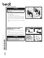
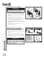
INSTALL THE HOOD
CAUTION
At least three installers are recommended
because of the large size and weight of this
range hood.
1. Adjust height of the telescoping support frame to ensure
a tight fit between the hood and finished ceiling. The
telescoping support frame height must be the same as the
wood support height.
2. Lift range hood into the ceiling opening.
3. Secure each suport frame to the wooden hood support
frame using 10 # 8 x 1-3/8" screws provided.See FIG. 5.
4. Connect ductwork. Duct tape all joints to ensure an air tight
seal.
5. Make all needed electrical connections. See WIRING
section.
FIG. 5
2X4 WOOD
FRAME
(10)
#8 X 1-3/8" SCREWS
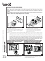
PREPARE THE HOOD FOR WIRING
CONNECTION AND BLOWER
INSTALLATION
1. Push in lock tabs (2) on the ends of perimeter panel. See
FIG. 6.
2. Open the panel and remove the mesh filters. See FIG. 7.
3. To ease access for blower installation, remove the central
panel by unscrewing the 3/16 x ¼" screws. See FIG. 7.
FIG. 6
FIG. 7
CAUTION
Re-install the aluminum mesh filters and
central panel as needed (See FIG. 7).
Make sure lock tabs are back in place once
installation is done (See FIG. 6).

INSTALLATION, USE & CARE INSTRUCTIONS
INSTALLATION
9
WIRING
WARNING
Risk of electric shock. Electrical wiring must be done by qualified personnel in
accordance with all applicable codes and standards. Before connecting wires, switch
power off at service panel and lock service disconnecting means to prevent power from
being switched on accidentally.
Home Power Wiring
1. Locate home power junction box (see FIG. 8 and 9) then remove the junction box cover.
2. Install a UL approved 7/8" strain relief (not included) on the house power cable. Run the power cable in the housing
then use the strain relief to secure it.
3. Connect power cable using included wire connectors. Connect BLACK to BLACK, WHITE to WHITE and GREEN or
BARE WIRE to GREEN. DO NOT FORGET TO CONNECT THE GROUND. See FIG. 9.
4. Reinstall the junction box cover. Make sure all wires are inside the junction box cover.
External Blower Wiring
1. Locate external blower junction box (see FIG. 8 and 10) then remove the junction box cover. Remove the knock-out
from the housing. See FIG. 8 for knock-out position. Remove wire protection.
2. Install a UL approved 7/8" strain relief (not included) on the external blower cable. Run the external blower cable in the
housing then use the strain relief to secure it.
3. Connect external blower cable using included wire connectors. Connect BLACK to BLACK, WHITE to WHITE and
GREEN or BARE WIRE to GREEN. DO NOT FORGET TO CONNECT THE GROUND. See FIG. 10.
4. Reinstall the junction box cover. Make sure all wires are inside the junction box cover.
CAUTION
Take care not to pinch wires while reinstalling wiring cover.
!
FIG. 9 FIG. 10
120 VAC INPUT
EXTERNAL BLOWER
INPUT
EXTERNAL BLOWER
INPUT
120 VAC
INPUT
STRAIN
RELIEF
STRAIN
RELIEF
FIG. 8

INSTALLATION, USE & CARE INSTRUCTIONS
INSTALLATION
10
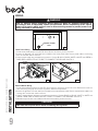
BLOWER INSTALLATION
This hood is compatible with the following blowers. Select a blower model among these: internal blower - PM6 or PM12,
exterior blower - EB9 or EB15, in-line blower - ILB6, ILB9 or ILB11. For exterior and in-line blowers, refer to the installation
instructions provided with the blower for more details.
NOTE: Rough-in plate included with exterior blower kit is not needed for ceiling hood application.
PM6 OR PM12 BLOWER INSTALLATION
PM6 Blower Plate Installation
FIG. 1
1. Attach blower to mounting plate with (6) 10-24 Hex
Nuts (included).
2. Attach ground wire from blower to ground stud with
(1) 10-24 Hex Nut (included).
GROUND STUD
PM12 Blower Plate Installation
FIG. 2
GROUND STUD
1. Attach blowers to mounting plate with (12) 10-24 Hex
Nuts (included).
2. Attach ground wires from blowers to ground studs
with (2) 10-24 Hex Nut (included).
GROUND STUD
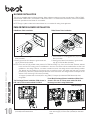
NOTES: There are four (4) possible outlet positions for PM6 and PM12: top, front, back and side. Remove selected
knock-out from the housing prior to install blower in the hood. The blower can be installed before or after hood
installation in the ceiling. However, it is easier to install the hood in the ceiling without internal blower installed.
The damper can be installed on the housing prior to install the hood in the ceiling with Side and Top outlet
positions only. Otherwise, install the damper once the hood is mounted in the ceiling. Position the damper on the
exterior of the hood using 8-18 screws (included).
10" damper (included with the hood) when using PM12, 8" damper (included with PM6 blower kit) when
using PM6.
Top Discharge Blower Installation (PM6 shown in
FIG. 3 & 5). Follow same method for PM12.
FIG. 3
1. Attach blower plate to hood with (4) 10-24 screws
(included) as illustrated above. 1. Attach blower plate to hood by inserting the hooks in the
slots and using (2) 10-24 screws (included) as illustrated
above.
Front/Back Discharge Blower Installation (PM12 Front
shown in FIG. 4 & 6). Follow same method for Side
Discharge and when using PM6 blower.
FIG. 4
Side Discharge

INSTALLATION, USE & CARE INSTRUCTIONS
INSTALLATION
11
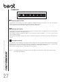
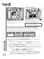
EXTERNAL BLOWER PROGRAMMING PROCEDURE
This range hood is designed to work with several different blower models. Before using the hood, the control must first
be programmed for your blower model in order to achieve proper operating speed:
1. Find the SETUP number that corresponds to the blower model that is installed with your range hood.
SETUP 1 SETUP 2 SETUP 3 (by default)
ILB6 EB15 EB9
ILB9 ILB11
NOTE: If no button is touched for more than 3 seconds while the hood is in programming mode, the hood will exit
the programming mode without saving the changes.
2. There must be power to the hood but the blower and lights must be turned off.
3. To change the setup, press and hold BLOWER and LIGHT buttons simultaneously for 6 seconds and release, then:
To set the range hood at SETUP 1, press BLOWER button until button 1 alone lights up.
To set the range hood at SETUP 2, press BLOWER button until both buttons 1 and 2 light up.
4. Press DELAY OFF button to save and leave programming mode.
5. If needed, verify which setting the hood is currently in. To do so:
Press and hold BLOWER and LIGHT buttons simultaneously for 6 seconds and release. Different
combinations of SPEED buttons (1 to 4) will turn ON for 3 seconds, depending on the setting.
If set at SETUP 3, SPEED buttons 1, 2, 3 and 4 will light up.
If set at SETUP 2, SPEED buttons 1 and 2 will light up.
If set at SETUP 1, SPEED button 1 will light up.
NOTE: To reset to default, press and hold BLOWER and LIGHT buttons simultaneously for 6 seconds and release.
Different combinations of SPEED buttons (1 to 4) will turn ON for 3 seconds. Press and hold LIGHT button
for 3 seconds then SPEED buttons will flash 3 times. Setting is back to original status.
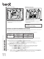
PM6 Blower Connection
FIG. 5
1. Swivel the connectors plate to unhide a connector.
2. Plug the blower power cord in the connector as
illustrated above.
Connectors plate
PM12 Blowers Connection
FIG. 6
1. Remove the connectors plate.
2. Plug each blower power cord in a connector as
illustrated above.
Service parts:
BLOWER (1) 600 CFM: S97021509
ADAPTER/DAMPER 8" ROUND: SV08543

INSTALLATION AND USE & CARE INSTRUCTIONS
OPERATION
12
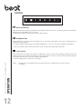
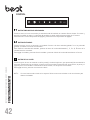
CONTROL
BLOWER BUTTON
When activated, the icon lights up and the blower turns on at the last saved speed. If there was no speed saved, the
blower will be set at speed 1.
To change the blower speed, press on the desired speed button 1, 2, 3 or 4. The current speed button will light up.
To turn off the blower, press on the blower button or press on the current speed button activated.
LIGHT BUTTON
When activated, the icon lights up as well as the dot(s) at the right of the icon that represent(s) the light intensity. By
pressing once on the icon, the first dot will light on. By pressing twice on the icon, the first and the second dots will light
on. By pressing three times on the icon, all three dots will light on.
To turn off the light, press a fourth time on the button.
DELAY OFF BUTTON
When activated, the icon lights up and blower current speed remains active for 10 min, then the blower turns off. Blower
speed can be changed within the 10 min delay.
To deactivate the delay off function, press on the delay off button.
NOTE: A remote control is included with the hood. See instructions included with the remote control for
more details.

INSTALLATION AND USE & CARE INSTRUCTIONS
MAINTENANCE & CLEANING
13
MAINTENANCE
ALWAYS SWITCH OFF THE ELECTRICITY SUPPLY
BEFORE CARRYING OUT ANY OPERATIONS ON THE
APPLIANCE.
Grease Filters
The grease filters should be cleaned frequently. Use a warm
dishwashing detergent solution. Grease filters are dishwasher
safe.
Clean the filters in the dishwasher using a non-phosphate
detergent. Discoloration of the filters may occur if using
phosphate detergents, or as a result of local water conditions
- but this will not affect filter performance. This discoloration
is not covered by the warranty. To minimize or prevent
discoloration, hand wash filters using a mild detergent.
Motor
The motor is permanently lubricated and never needs oiling If
the motor bearings make excessive or unusual noise, replace
the motor with the exact service motor. The impeller should
also be replaced.
STAINLESS STEEL CLEANING
Do:
• Regularly wash with clean cloth or rag soaked
with warm water and mild soap or liquid dish
detergent.
• Always clean in the direction of original polish
lines.
• Always rinse well with clear water (2 or 3 times)
after cleaning. Wipe dry completely.
• You may also use a specialized household
stainless steel cleaner.
Don’t:
• Use any steel or stainless steel wool or any
other scrapers to remove stubborn dirt.
• Use any harsh or abrasive cleansers.
• Allow dirt to accumulate.
• Let plaster dust or any other construction
residues reach the unit. During construction/
renovation, cover the unit to make sure no dust
sticks to the stainless steel surface.
Avoid when choosing a detergent:
• Any cleaners that contain bleach will attack
stainless steel.
• Any products containing: chloride, fluoride,
iodide, bromide will deteriorate surfaces
rapidly.
• Any combustible products used for cleaning
such as acetone, alcohol, ether, benzol,
etc., are highly explosive and should never be
used close to a range.

INSTALLATION, USE & CARE INSTRUCTIONS
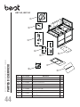
SERVICE PARTS
14
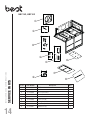
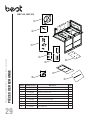
KEY NO.PART NUMBER DESCRIPTION QTY.
1 S1106832 10" ROUND ADAPTOR WITH DAMPER 1
2 S1106831 USER INTERFACE 1
3 S1106829 CAPACITOR ASSEMBLY 1
4 S1106833 REMOTE CONTROL KIT 1
5 S1106828 POWER UNIT ASSEMBLY 1
6 S1106836 PLASTIC CAP (8) 1
7 S1106835 FILTERS (SET OF 2) 1
8 S1106834 PARTS BAG (6 WIRE NUTS AND 10 SCREWS)1
9 S1106827 LED MODULE (1) 1
HBC143, HBC163

INSTALLATION, USE & CARE INSTRUCTIONS
WARRANTY
15
Limited Warranty
Warranty Period and Exclusions: Broan-NuTone LLC (the “Company”) warrants to the original consumer purchaser of its product (“you”) that the
product (the “Product”) will be free from material defects in the materials or its workmanship for a period of five (5) years from the date of original
purchase (or such longer period as may be required by applicable law) or a period of two (2) years from the date of service for any labor provided on the
Product. The limited warranty period for any replacement parts provided by the Company and for any Products repaired or replaced under this limited
warranty shall be the remainder of the original warranty period (or such longer period as may be required by applicable law).
THIS WARRANTY DOES NOT COVER FLUORESCENT LAMP STARTERS, TUBES AND BULBS, FUSES, FILTERS, DUCTS, ROOF CAPS,
WALL CAPS AND OTHER ACCESSORIES FOR DUCTING. This warranty does not cover (a) normal maintenance and service, (b) normal wear and
tear, (c) any Products or parts which have been subject to misuse, abuse, abnormal usage, negligence, accident, improper or insufficient maintenance,
storage or repair (other than repair by the Company), (d) damage caused by faulty installation, or installation or use contrary to recommendations or
instructions, (e) any Product that has been moved from its original point of installation, (f) damage caused by exposure to salt air, (g) damage in transit,
(h) natural wear of finish, (i) Products in commercial or nonresidential use, or (j) damage caused by fire, flood or other act of God or (k) Products with
altered, defaced or removed serial numbers. This warranty covers only Products sold to consumers in North America.
This warranty supersedes all prior warranties and, subject to applicable law, is not transferable from the original consumer purchaser.
No Other Warranties: This Limited Warranty contains the Company’s sole obligation and your sole remedy for defective products. The foregoing
warranties are exclusive and in lieu of any other warranties and conditions, express or implied. TO THE MAXIMUM EXTENT PERMITTED BY
APPLICABLE LAW, THE COMPANY DISCLAIMS AND EXCLUDES ALL OTHER EXPRESS WARRANTIES AND CONDITIONS, AND
DISCLAIMS AND EXCLUDES ALL WARRANTIES AND CONDITIONS IMPLIED BY LAW, INCLUDING WITHOUT LIMITATION THOSE OF
MERCHANTABILITY AND FITNESS FOR A PARTICULAR PURPOSE. To the extent that applicable law prohibits the exclusion of implied warranties
or conditions, the duration of any applicable implied warranty or condition is limited to the period specified for the express warranty above. Some
jurisdictions (which may include th eProvince of Québec or specific US states) do not allow limitations on how long an implied warranty lasts, so the
above limitation may not apply to you. Any oral or written description of the Product is for the sole purpose of identifying it and shall not be construed
as an express warranty.
Whenever possible, each provision of this Limited Warranty shall be interpreted in such manner as to be effective and valid under applicable law, but if
any provision is held to be prohibited or invalid, such provision shall be ineffective only to the extent of such prohibition or invalidity, without invalidating
the remainder of such provision or the other remaining provisions of the Limited Warranty.
Remedy: During the applicable limited warranty period, the Company will, at its option, provide replacement parts for, or repair or replace, without
charge, any Product or part thereof, to the extent the Company finds it to be covered by and in breach of this limited warranty under normal use and
service. The Company will ship the repaired or replaced Product or replacement parts to you at no charge. You are responsible for all costs for removal,
reinstallation and shipping, insurance or other freight charges incurred in the shipment of the Product or part to the Company. If you must send the
Product or part to the Company, as instructed by the Company, you must properly pack the Product or part—the Company is not responsible for
damage in transit. The Company reserves the right to utilize reconditioned, refurbished, repaired or remanufactured Products or parts in the warranty
repair or replacement process. Such Products and parts will be comparable in function and performance to an original Product or part and warranted
for the remainder of the original warranty period (or such longer period as may be required by applicable law).
Company reserves the right, in its sole discretion, to refund the money actually paid by you for the Product. If the Product or component is no longer
available, replacement may be made with a similar product of equal or greater value, at Company’s sole discretion. This is your sole and exclusive
remedy for breach of this limited warranty.
Exclusion of Damages: THE COMPANY’S OBLIGATION TO PROVIDE REPLACEMENT PARTS, OR REPAIR, REPLACE OR REFUND, AT
THE COMPANY’S OPTION, SHALL BE YOUR SOLE AND EXCLUSIVE REMEDY UNDER THIS LIMITED WARRANTY AND THE COMPANY’S
SOLE AND EXCLUSIVE OBLIGATION. THE COMPANY SHALL NOT BE LIABLE FOR INCIDENTAL, INDIRECT, CONSEQUENTIAL OR
SPECIAL DAMAGES ARISING OUT OF OR IN CONNECTION WITH THE PRODUCT, ITS USE OR PERFORMANCE.
Some jurisdictions do not allow the exclusion or limitation of incidental or consequential damages, so the above limitation or exclusion may not apply
to you. This warranty gives you specific legal rights, and you may also have other rights, which vary from jurisdiction to jurisdiction. The disclaimers,
exclusions, and limitations of liability under this warranty will not apply to the extent prohibited by applicable law.
This warranty covers only replacement or repair of defective Products or parts thereof at the Company’s main facility and does not include the cost of
field service travel and living expenses.
Any assistance the Company provides to or procures for you outside the terms, limitations or exclusions of this limited warranty
will not constitute a waiver of such terms, limitations or exclusions, nor will such assistance extend or revive the warranty.
The Company will not reimburse you for any expenses incurred by you in repairing or replacing any defective Product, except for those incurred with
the Company’s prior written permission.
How to Obtain Warranty Service: To qualify for warranty service, you must (a) notify the Company at the address or telephone number stated below
within seven (7) days of discovering the covered defect, (b) give the model number and part identification and (c) describe the nature of any defect in
the Product or part. At the time of requesting warranty service, you must present evidence of the original purchase date. If you cannot provide a copy
of the original written limited warranty, then the terms of the Company’s most current written limited warranty for your particular product will control.
PRODUCT SPECIFICATIONS
All illustrations and specifications in this catalog are based on the latest product information available at time of production. Broan-NuTone LLC and
Best® reserves the right to make changes at any time, without notice, in prices, colors, materials, specifictions and models, place of manufacture and
to discontinue models or equipment.
BEST 926 West State Street, Hartford, Wisconsin, USA 53027 BestRangeHoods.com 800-558-1711
BEST 550 Lemire Blvd., Drummondville, Québec, Canada J2C 7W9 BestRangeHoods.ca 800-567-3855

Hottes pour plafond
Série HBC1
DIRECTIVES D'INSTALLATION,
D'UTILISATION ET D'ENTRETIEN
Numéro de série :
1105483D
BEST 550 boul. Lemire, Drummondville, Québec, Canada J2C 7W9 BestRangeHoods.ca 800 567-3855
BEST 926 West State Street, Hartford, Wisconsin, USA 53027 BestRangeHoods.com 800 558-1711

DIRECTIVES D’INSTALLATION, D’UTILISATION ET D’ENTRETIEN
TABLE DES MATIÈRES
1717
Sécurité . . . . . . . . . . . . . . . . . . . . . . . . . . . . . . . . . . . . . . . . . . . . . . . . . . 18-19
Installation . . . . . . . . . . . . . . . . . . . . . . . . . . . . . . . . . . . . . . . . . . . . . . . . 20-26
Outils et accessoires recommandés . . . . . . . . . . . . . . . . . . . . . . . . . . . . . . . . . . . . . 20
Spécifications de la hotte . . . . . . . . . . . . . . . . . . . . . . . . . . . . . . . . . . . . . . . . . . . . . .20
Installation des conduits . . . . . . . . . . . . . . . . . . . . . . . . . . . . . . . . . . . . . . . . . . . . . . 21
Position de sortie du ventilateur . . . . . . . . . . . . . . . . . . . . . . . . . . . . . . . . . . . . . . . . .21
Préparation de l'ouverture au plafond et du support de la hotte . . . . . . . . . . . . . . . . . . .22
Installation de la hotte . . . . . . . . . . . . . . . . . . . . . . . . . . . . . . . . . . . . . . . . . . . . . . . .23
Préparation de la hotte pour le branchement et l'installation du ventilateur . . . . . . . . . . .23
Branchement . . . . . . . . . . . . . . . . . . . . . . . . . . . . . . . . . . . . . . . . . . . . . . . . . . . . . .24
Installation du ventilateur . . . . . . . . . . . . . . . . . . . . . . . . . . . . . . . . . . . . . . . . . . . 25-26
Procédure de programmation du ventilateur externe . . . . . . . . . . . . . . . . . . . . . . . . . . .26
Fonctionnement . . . . . . . . . . . . . . . . . . . . . . . . . . . . . . . . . . . . . . . . . . . . . .27
Entretien et nettoyage . . . . . . . . . . . . . . . . . . . . . . . . . . . . . . . . . . . . . . . . . .28
Filtre(s) à graisses
Nettoyage de l'acier inoxydable
Pièces de rechange . . . . . . . . . . . . . . . . . . . . . . . . . . . . . . . . . . . . . . . . . . . .29
Garantie . . . . . . . . . . . . . . . . . . . . . . . . . . . . . . . . . . . . . . . . . . . . . . . . . . . . .30

DIRECTIVES D’INSTALLATION, D’UTILISATION ET D’ENTRETIEN
SÉCURITÉ
18
Pour enregistrer votre produit, veuillez visiter notre site Internet :
Aux États-Unis - BestRangeHoods.com
Au Canada - BestRangeHoods.ca
Pour de l'assistance technique, veuillez composer le numéro de téléphone suivant :
Aux États-Unis - 800-558-1711
Au Canada - 800-567-3855
Installateur : Laisser ce manuel au propriétaire.
VEUILLEZ LIRE ET CONSERVER CES DIRECTIVES
Conçu pour usage domestique seulement !!
! AVERTISSEMENT
AFIN DE RÉDUIRE LES RISQUES D’INCENDIE, D’ÉLECTROCUTION OU DE BLESSURES
CORPORELLES, SUIVEZ LES DIRECTIVES SUIVANTES :
• N’utilisez cet appareil que de la façon prévue par le manufacturier. Si vous avez des questions, contactez le manufacturier
à l’adresse ou au numéro de téléphone indiqués dans la garantie.
• Avant de réparer ou de nettoyer l’appareil, couper l’alimentation électrique en verrouillant le panneau de distribution afin
d’éviter sa remise en marche accidentelle. Si le panneau de distribution ne peut être verrouillé, y fixer un avertissement
en évidence, telle qu’une étiquette de couleur vive.
• Les travaux d’installation et de raccordement électrique doivent être effectués par une personne qualifiée, conformément
aux codes et aux standards de construction, incluant ceux concernant la protection contre les incendies.
• Une quantité d’air adéquate est requise afin d’assurer une bonne combustion et l’évacuation des gaz par la cheminée
dans le cas des équipements alimentés au gaz afin de prévenir les retours de cheminée. Conformez-vous aux instructions
et aux standards de sécurité des manufacturiers d’équipement de chauffage, tel qu’ils sont publiés par la National Fire
Protection Association (NFPA) et l’American Society for Heating, Refrigeration and Air Conditioning Engineers (ASHRAE)
ainsi que les responsables des codes locaux.
• Veillez à ne pas endommager le câblage électrique ou d’autres équipements non apparents lors de la découpe ou du
perçage du mur ou du plafond.
• Les ventilateurs avec conduits doivent toujours évacuer l’air à l’extérieur.
• Ne pas utiliser cet appareil avec une commande de vitesse à semi-conducteur additionnelle.
• Afin de réduire les risques d’incendie, n’utilisez que des conduits de métal.
• Cet appareil doit être mis à la terre.
• Il est recommandé de porter des lunettes et des gants de sécurité lors de l’installation, de l’entretien ou de la réparation
de cet appareil.
• Lorsqu’une réglementation est en vigueur et qu’elle comporte des exigences d’installation et/ou de certification plus
restrictives, lesdites exigences prévalent sur celles de ce document et l’installateur entend s’y conformer à ses frais.

DIRECTIVES D’INSTALLATION, D’UTILISATION ET D’ENTRETIEN
SÉCURITÉ
19
! AVERTISSEMENT
AFIN DE RÉDUIRE LES RISQUES DE FEU DE CUISINIÈRE :
A. Ne jamais laisser les appareils de cuisson sans surveillance lorsqu’ils sont réglés
à feu vif. Les débordements engendrent de la fumée et des déversements
graisseux pouvant s’enflammer. Chauffez l’huile lentement, à feu doux ou moyen.
B. Mettez toujours la hotte en marche lorsque vous cuisinez à feu vif ou que vous
cuisinez des mets flambés (par ex. : crêpes Suzette, cerises jubilé, steaks au
poivre flambés).
C. Nettoyez régulièrement la roue du ventilateur. Ne laissez pas la graisse
s’accumuler sur le ventilateur, le filtre ou les conduits d’évacuation.
D. Utilisez le bon format de casserole. Servez-vous toujours de casseroles
et d’ustensiles appropriés à la dimension de la surface chauffante.
AFIN DE RÉDUIRE TOUT RISQUE DE BLESSURES LORS D’UN FEU DE CUISINIÈRE, SUIVEZ
CES DIRECTIVES* :
1. ÉTOUFFEZ LES FLAMMES avec un couvercle hermétique, une tôle à biscuits
ou un plateau métallique et ensuite, éteignez le brûleur. PRENEZ SOIN D’ÉVITER
les brûlures. SI LES FLAMMES NE S’ÉTEIGNENT PAS IMMÉDIATEMENT,
ÉVACUEZ LES LIEUX ET APPELEZ LES POMPIERS.
2. NE PRENEZ JAMAIS UNE CASSEROLE EN FLAMMES DANS VOS MAINS.
Vous pourriez vous brûler.
3. N’UTILISEZ PAS D’EAU, incluant un linge à vaisselle ou une serviette mouillée,
cela pourrait occasionner une violente explosion de vapeur.
4. N’utilisez un extincteur QUE DANS LE CAS OÙ :
A. Vous possédez un extincteur de classe ABC et vous en connaissez
le fonctionnement.
B. Le feu est petit et limité à l’endroit où il a débuté.
C. Les pompiers ont été avisés.
D. Vous pouvez combattre l’incendie en ayant accès à une sortie de secours.
* Tirées du Kitchen Fire Safety Tips publié par la NFPA.
! ATTENTION
!
• Pour une utilisation résidentielle et à l’intérieur seulement.
• Afin de réduire les risques d’incendie et évacuer l’air adéquatement, assurez-vous que les conduits évacuent l’air
à l’extérieur. Ne pas évacuer l’air dans des espaces restreints comme l’intérieur des murs ou plafond ou dans le
grenier, faux plafond ou garage.
• Soyez prudents lors de l’utilisation d’agents nettoyants ou de détergents.
• Évitez d’utiliser sous la hotte des produits alimentaires pouvant s’enflammer.
• Pour usage domestique seulement. Ne pas utiliser pour évacuer des vapeurs ou des matières dangereuses ou
explosives.
• Afin d’éviter tout dommage au moteur et de débalancer ou de rendre bruyante la roue du moteur, garder votre
appareil à l’abri des poussières de gypse et de construction/rénovation, etc.
• Le moteur de votre hotte possède une protection thermique qui éteindra automatiquement le moteur s’il devient
surchauffé. Le moteur redémarrera automatiquement une fois refroidi. Si le moteur continue à arrêter et à
redémarrer, faites-le vérifier.
• Pour une meilleure évacuation des odeurs de cuisson, le bas de votre hotte devrait être situé à UN MINIMUM de
48 po et à un maximum recommandé de 84 po au-dessus de la surface de cuisson.
• Veuillez consulter l’autocollant apposé à l’intérieur de la hotte pour plus d’information ou autres exigences.

DIRECTIVES D’INSTALLATION, D’UTILISATION ET D’ENTRETIEN
INSTALLATION
20
OUTILS ET ACCESSOIRES RECOMMANDÉS
• Ruban à mesurer
• Tournevis Phillips no 2
• Tourne-écrou ou douille 3/8 po
• Tournevis à lame plate (pour dégager les ouvertures
préamorcées)
• Scie
• Cisailles à tôle
• Pinces
• Ruban adhésif de métal
• Ciseaux (pour couper le ruban adhésif de métal)
• Crayon
• Pince à dénuder
• Serre-fils de 7/8 po de diamètre (un pour fixer le câble
d'alimentation électrique domestique à la hotte et un
autre pour fixer le câble du ventilateur externe à la
hotte)
• Perceuse et mèche de 1/8 po
SPÉCIFICATIONS DE LA HOTTE
43-
5
/1
6 | 63-1/2
27-9
/1
6
2-5/8
Min:
14
Max:
23-3/4
5-1/2
35-9/16
C/L
C/L
C/L
25-3
/1
6
41 |
61-
1/4
23-
1
1/
16
1-3/16
8-3/8
C/L
4-5/8
8-1/16
4-1/8
8-3/16
ENTRÉE 120 VCA
ENTRÉE
VENTILATEUR
EXTERNE
Entrée
électrique
La page est en cours de chargement...
La page est en cours de chargement...
La page est en cours de chargement...
La page est en cours de chargement...
La page est en cours de chargement...
La page est en cours de chargement...
La page est en cours de chargement...
La page est en cours de chargement...
La page est en cours de chargement...
La page est en cours de chargement...
La page est en cours de chargement...
La page est en cours de chargement...
La page est en cours de chargement...
La page est en cours de chargement...
La page est en cours de chargement...
La page est en cours de chargement...
La page est en cours de chargement...
La page est en cours de chargement...
La page est en cours de chargement...
La page est en cours de chargement...
La page est en cours de chargement...
La page est en cours de chargement...
La page est en cours de chargement...
La page est en cours de chargement...
La page est en cours de chargement...
-
 1
1
-
 2
2
-
 3
3
-
 4
4
-
 5
5
-
 6
6
-
 7
7
-
 8
8
-
 9
9
-
 10
10
-
 11
11
-
 12
12
-
 13
13
-
 14
14
-
 15
15
-
 16
16
-
 17
17
-
 18
18
-
 19
19
-
 20
20
-
 21
21
-
 22
22
-
 23
23
-
 24
24
-
 25
25
-
 26
26
-
 27
27
-
 28
28
-
 29
29
-
 30
30
-
 31
31
-
 32
32
-
 33
33
-
 34
34
-
 35
35
-
 36
36
-
 37
37
-
 38
38
-
 39
39
-
 40
40
-
 41
41
-
 42
42
-
 43
43
-
 44
44
-
 45
45


Best HBC1 Guide d'installation
- Catégorie
- Hottes
- Taper
- Guide d'installation
dans d''autres langues
- English: Best HBC1 Installation guide
- español: Best HBC1 Guía de instalación


