Delta Faucet T27833-BL Mode d'emploi
- Catégorie
- Articles sanitaires
- Taper
- Mode d'emploi

MultiChoice® Valve Trim with Diverter
Installation Instructions
Owners Manual
Models T27
Write purchased model number here.
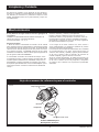
You May Need
THIS VALVE MEETS OR EXCEEDS THE
FOLLOWING STANDARDS: ASME A112.18.1/
CSA B125.1 and ASSE 1016 (Type -P- or -T-).
CAUTION: This system/device must be set by the
installer to ensure safe, maximum temperature.
Any change in the setting may raise the discharge
temperature above the limit considered safe and
may lead to hot water burns.
NOTICE TO INSTALLER: CAUTION!–As the
installer of this valve, it is your responsibility
to properly INSTALL and ADJUST this valve
per the instructions given. This valve does
not automatically adjust for inlet temperature
changes, therefore, someone must make the
necessary Rotational Limit Stop adjustments
at the time of installation and further adjustments
may be necessary due to seasonal water
temperature change. YOU MUST inform the
owner/user of this requirement by following
the instructions. If you or the owner/user are
unsure how to properly make these adjustments
please refer to page 6 and if still uncertain, call
us at 1-800-345-DELTA.
After installation and adjustment, you must ax
your name, company name and the date you
adjusted the Rotational Limit Stop to the caution
label provided and apply or attach the label to
the back side of the closest cabinet door and the
warning label to the water heater. Leave this
Instruction Sheet for the owner’s/user’s
reference.
WARNING: This pressure balanced or
thermostatic bath valve is designed
to minimize the eects of outlet water
temperature changes due to inlet pressure
changes, commonly caused by dishwashers,
washing machines, toilets and the like. It may
not provide protection from hot water burns
when there is a failure of other temperature
controlling devices elsewhere in the
plumbing system, if the rotational limit stop
is not properly set or if the hot water
temperature is changed after the settings are
made or if the water inlet changes
due to seasonal changes.
WARNING: Do not install a shut-o device on
either outlet of this valve. When this type of
device shuts o the water ow, it can defeat
the ability of the valve to balance the hot and
cold water pressures.
Rev. B1
104438
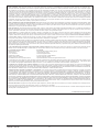
Table of Contents:
Warranties ............................................................................... Page 2
Installation Instructions ........................................................... Pages 3 - 7
Clean and care......................................................................... Page 9
Maintenance ............................................................................ Page 9
Cartridge Summary Reference Sheet ..................................... Page 9
For additional replacement parts, visit www.deltafaucet.com
07/13/2020
3/32"

104438 Rev. B 2
Parts and Finish. All parts (other than electronic parts and batteries) and finishes of Delta® faucets purchased from authorized Delta sellers are warranted to the original
consumer purchaser to be free from defects in material and workmanship for as long as the original consumer purchaser owns the home in which the faucet was first
installed. For commercial purchasers, (a) the warranty period is ten (10) years for multi-family residential applications and (b) five (5) years for all other commercial
applications, in each case from the date of original purchase. For purposes of this warranty, the term “multi-family residential application” refers to the purchase of the
faucet from an authorized Delta seller by a purchaser who owns but does not live in the residential dwelling in which the faucet is initially installed, such as in a rented or
leased single unit or multi-unit detached home (duplex or townhome), or a condominium, apartment building or community living center. The following installations are not
considered multi-family residential applications, are excluded from the 10-year warranty and are subject to the 5-year warranty: industrial, institutional or other business
premises, such as a dormitory, hospitality premises (hotel, motel or extended stay location), airport, educational facility, long- or short-term healthcare facility (hospital,
rehabilitation center, nursing, assisted or staged-care living unit), public space or common area.
Parts and Finish for Delta® Recertified Faucets. Delta Faucet Company offers for sale on deltafaucet.com Delta® Recertified faucets. All parts (other than electronic
parts and batteries) and finishes of these Delta® Recertified faucets are warranted to the original consumer purchaser to be free from defects in material and workmanship
for ten (10) years from the date of original purchase. For commercial purchasers, the warranty period is one (1) year from the date of original purchase.
Electronic Parts. Electronic parts (other than batteries), if any, of Delta® faucets purchased from deltafaucet.com or authorized Delta sellers are warranted to the original
consumer purchaser to be free from defects in material and workmanship for five (5) years from the date of original purchase or, for commercial purchasers, for one (1)
year from the date of original purchase. No warranty is provided on batteries.
What We Will Do. Delta Faucet Company will repair or replace, free of charge, during the applicable warranty period (as described above), any part or finish that proves
defective in material and/or workmanship under normal installation, use and service. If repair or replacement is not practical, Delta Faucet Company may elect to refund
the purchase price in exchange for the return of the product. These are your exclusive remedies.
What Is Not Covered. Because Delta Faucet Company is unable to control the quality of Delta products sold by unauthorized sellers, unless otherwise prohibited by law,
this warranty does not cover Delta products purchased from unauthorized sellers.
Any labor charges incurred by the purchaser to repair, replace, install or remove this product are not covered by this warranty. Delta Faucet Company shall not be liable
for any damage to the faucet resulting from reasonable wear and tear, outdoor use, misuse (including use of the product for an unintended application), freezing water,
abuse, neglect or improper or incorrectly performed installation, maintenance or repair, including failure to follow the applicable care and cleaning instructions. Delta Faucet
Company recommends using a professional plumber for all installation and repair of faucets. We also recommend that you use only genuine Delta® replacement parts.
What You Must Do To Obtain Warranty Service or Replacement Parts. A warranty claim may be made and replacement parts may be obtained by calling 1 800 345
DELTA (3358) or by contacting us by mail or online as follows (please include your model number and date of original purchase):
In the United States and Mexico: In Canada:
Delta Faucet Company Masco Canada Limited, Plumbing Group
Product Service Technical Service Centre
55 E. 111th Street 350 South Edgeware Road
Indianapolis, IN 46280 St. Thomas, Ontario, Canada N5P 4L1
Attention: Customer Solutions Attention: Customer Service
www.deltafaucet.com/service-parts/contact-us http://www.deltafaucet.ca/customersupport/assistance.html
Proof of purchase (original sales receipt) from the original purchaser must be made available to Delta Faucet Company for all warranty claims unless the purchaser has
registered the product with Delta Faucet Company or the product is a Delta® Recertified product purchased from deltafaucet.com. This warranty applies only to Delta®
faucets manufactured after January 1, 2019 and installed in the United States of America, Canada and Mexico.
Limitation on Duration of Implied Warranties. Please note that some states/provinces (including Quebec) do not allow limitations on how long an implied warranty
lasts, so the below limitations may not apply to you. TO THE MAXIMUM EXTENT PERMITTED BY APPLICABLE LAW, ANY IMPLIED WARRANTY, INCLUDING THE
IMPLIED WARRANTIES OF MERCHANTABILITY AND OF FITNESS FOR A PARTICULAR PURPOSE, IS LIMITED TO THE STATUTORY PERIOD OR THE DURATION
OF THIS WARRANTY, WHICHEVER IS SHORTER.
Limitation of Special, Incidental or Consequential Damages. Please note that some states/provinces (including Quebec) do not allow the exclusion or limitation of
special, incidental or consequential damages, so the below limitations and exclusions may not apply to you. TO THE MAXIMUM EXTENT PERMITTED BY APPLICABLE
LAW, THIS WARRANTY DOES NOT COVER, AND DELTA FAUCET COMPANY SHALL NOT BE LIABLE FOR, ANY SPECIAL, INCIDENTAL OR CONSEQUENTIAL
DAMAGES (INCLUDING LABOR CHARGES TO REPAIR, REPLACE, INSTALL OR REMOVE THIS PRODUCT), WHETHER ARISING OUT OF BREACH OF ANY
EXPRESS OR IMPLIED WARRANTY, BREACH OF CONTRACT, TORT, OR OTHERWISE. DELTA FAUCET COMPANY SHALL NOT BE LIABLE FOR ANY DAMAGE
TO THE FAUCET RESULTING FROM REASONABLE WEAR AND TEAR, OUTDOOR USE, MISUSE (INCLUDING USE OF THE PRODUCT FOR AN UNINTENDED
APPLICATION), FREEZING WATER, ABUSE, NEGLECT OR IMPROPER OR INCORRECTLY PERFORMED INSTALLATION, MAINTENANCE OR REPAIR,
INCLUDING FAILURE TO FOLLOW THE APPLICABLE INSTALLATION, CARE AND CLEANING INSTRUCTIONS. Notice to residents of the State of New Jersey: The
provisions of this warranty, including its limitations, are intended to apply to the fullest extent permitted by the laws of the State of New Jersey.
Additional Rights. This warranty gives you specific legal rights, and you may also have other rights which vary from state/province to state/province.
This is Delta Faucet Company’s exclusive written warranty and the warranty is not transferable.
If you have any questions or concerns regarding our warranty, please contact us as provided above or view our Warranty FAQs at www.deltafaucet.com.
Limited Warranty on Delta® Faucets
© 2020 Delta Faucet Company

104438 Rev. B
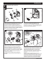
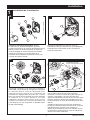
Installation
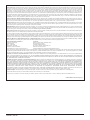
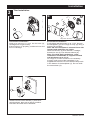
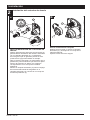
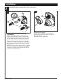
1Cartridge Installation
A. B.
Turn o water supplies. Remove cover (1),
bonnet nuts (2) and test caps (3) from the
rough-in body (4).
Place a bucket or small container over the front
of the valve body and slowly open the water
supplies to ush any debris from the supply
lines before installing the cartridge. Turn the
water supplies back o.
Insert adapter assembly (1) into rough-in
body (2). Make sure the adapter assembly
is correctly positioned and is pressed all
the way down inside rough-in body.
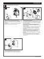
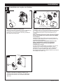
Rotate cartridge (1) so the words “HOT SIDE”
(2) appear on the left. Insert cartridge assembly
into rough-in body. Make sure the key (3) on the
valve cartridge is fully engaged with the slot in
the brass body (4). Insert bonnet nut (5) over
the cartridge and thread onto the body. Hand
tighten securely, slide o-ring (6) over bonnet
and cartridge. A light coating of plumbers
grease applied to o-rings may aid in assembly.
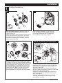
For the exceptions of back to back or reverse
installations (hot on right and cold on left) only:
Rotate valve cartridge (1) so “HOT SIDE” (2)
appears on the right.
Apply silicone lube to the three o-rings shown
above to make the cartridge easier to install and
remove from the rough-in body.
Install the cartridge making sure that the keys
are fully engaged with the slot in the rough-in
body (see step C).
Slide o-ring (3) and bonnet nut (4) over the
cartridge and thread onto the rough-in body.
Hand tighten securely.
3
C. Back to back Installation
Normal Installation
(changes not required)
Reverse
Installation
Cold
Hot
1
2
3
4
2
3
1
2
1
2
3
4
53
4
2
4
31
6

104438 Rev. B
Installation
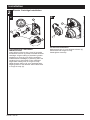
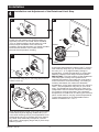
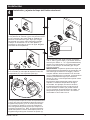
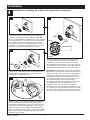
2Diverter Cartridge Installation
4
For Bonnet Installation
Slide bonnet nut (1) over diverter sleeve (2)
and thread into rough-in body.
Hand tighten securely.
B.
FOR DIVERTER CARTRIDGE
INSTALLATION:
Apply silicone lube to the o-ring (2) to make
the diverter sleeve (3) easier to install diverter
cartridge. A light coating of plumbers grease
applied to o-rings (4) may aid in assembly.
Install diverter cartridge (1) assuring that the
locating pin on the bottom of the cartridge
aligns with mating hole in rough-in body.
Slide diverter sleeve (3) over cartridge stem
aligning tabs on the diverter sleeve with slots
in rough-in body (5).
A.
3
1
5
2
1
2
5
4

104438 Rev. B
Installation
3
5
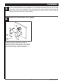
Trim Installation
Trim Sleeve Installation
Slide trim sleeve (1) over the bonnet (2),
cartridge and rough-in body.
Ensure sleeve is properly positioned over the
front of cartridge.
Escutcheon Installation
For nished wall thickness up to 1 1/8". Secure
the backplate (1) to the rough-in body (2) using 4
screws (3) provided.
Note: Be sure backplate is oriented front side
forward and markings are visible.
Slide escutcheon (4) over diverter cartridge,
thread trim nut (5) onto diverter sleeve (6).
Note: For thick wall installations, order
installation kit RP90543 to support nished
wall thickness up to 2 1/8".
On rough or uneven surfaces it is necessary
to apply caulk around the backplate (1) to
supplement the seal. Do not caulk the drip notch
in the bottom of the backplate (1). Do not caulk
the escutcheon (4).
1
2
A. B. 12
5
4
Install volume control handle (1) with lever
pointing down, then turn to the on position.
DO NOT SECURE WITH SCREW.
3
3
6
Drip notch
7
C.
1

104438 Rev. B
Installation
4
6
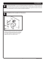
Installation and Adjustment of the Rotational Limit Stop
Place the rotational limit stop (1) in
volume
handle (2) and rotate to the mixed
position (if
required). DO NOT SECURE WITH
SCREW.
Turn on water supplies; let the
water
run until
both hot and cold water is as hot/
cold as
possible. Place thermometer in a plastic tumbler,
and hold the tumbler in the water stream.
Record the temperature reading.
If the water temperature is above 120°F, remove
and rotate the limit stop (1) clockwise one tooth
for every 4°F - 6°F (approximate) change in
temperature. If water temperature is cooler than
desired, rotate the limit stop counterclockwise.
IMPORTANT: The rst position of the Rotational
Limit Stop (the Limiter) is the position that
restricts the rotation of the stem the most and is
at the maximum clockwise setting. According to
industry standards, the maximum allowable
temperature of the water exiting from the valve is
120oF. This temperature may vary in your local
area. The Rotational Limit Stop may need to be
readjusted if the inlet water temperature changes.
For instance, during the winter, the cold water
temperature is colder than it is during the summer
which could result in varying outlet temperatures.
Typical temperature for a comfortable bath or
shower is between 90o–110o F.
Secure temperature control knob (1) with screw
(2). See next step (D) for securing temperature
control cover (3).
Snap temperature control cover over temperature
control knob by rst aligning smaller tab (1) on
cover with receiving slot (2) on temperature knob.
Swing larger tab (3) to engage with snap feature
(4). Note: If dis-assembly is required, reverse
this motion, disengaging larger tab (3) from snap
feature (4) rst.
D.
42
1
3
B.
Hotter
Colder
1
A.
1
C.
1
2
3
2

104438 Rev. B
Potential scald or thermal shock injury could result due to cross ow if outlet at the shower is
blocked or restricted (e.g., pause control on showerhead). Be sure to point showerhead away
from you when re-starting ow or install inlet check valves on both supply lines to prevent
possible injury.
7
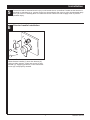
6Diverter handle Installation
Diverter Handle Installation
Slide diverter handle (1) onto trim sleeve (2).
Using a allen wrench, insert set screw (3) into
handle (1). Applying pressure, insert set screw
cover (4) until properly seated.
Installation
5
2
1
3
4

104438 Rev. B 8
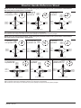
Diverter Handle Reference Sheet
2nd Position
2 ª Posición
2e position
3rd Position
3 ª posición
3e position
1st Position
1 ª posición
1ère position
2nd Position
2 ª Posición
2e position
3rd Position
3 ª posición
3e position
Outlet 1
Salida 1
Sortie 1
Outlet 2
Salida 2
Sortie 2
Outlet 3
Salida 3
Sortie 3
In / Entrada / Entrée
4th Position
4 ª posición
4e position
5th Position
5 ª posición
5e position
6th Position
6 ª posición
6e position
Water Flow For 3 Function Diverter / Flujo de agua para Desviadores de 3 posiciones / Écoulement
de l’eau pour les inverseurs à 3 positions
Water Flow For 6 Function Diverter / Flujo de agua para Desviadores de 6 posiciones / Écoulement
de l’eau pour les inverseurs à 6 positions
In / Entrada / Entrée In / Entrada / Entrée
In / Entrada / Entrée In / Entrada / Entrée In / Entrada / Entrée
Outlet 1
Salida 1
Sortie 1
Outlet 2
Salida 2
Sortie 2
Outlet 3
Salida 3
Sortie 3
Outlet 1
Salida 1
Sortie 1
Outlet 2
Salida 2
Sortie 2
Outlet 3
Salida 3
Sortie 3
Outlet 1
Salida 1
Sortie 1
Outlet 2
Salida 2
Sortie 2
Outlet 3
Salida 3
Sortie 3
Outlet 1
Salida 1
Sortie 1
Outlet 2
Salida 2
Sortie 2
Outlet 3
Salida 3
Sortie 3
Outlet 1
Salida 1
Sortie 1
Outlet 2
Salida 2
Sortie 2
Outlet 3
Salida 3
Sortie 3
Outlet 1
Salida 1
Sortie 1
Outlet 2
Salida 2
Sortie 2
Outlet 3
Salida 3
Sortie 3
Outlet 1
Salida 1
Sortie 1
Outlet 2
Salida 2
Sortie 2
Outlet 3
Salida 3
Sortie 3
Outlet 1
Salida 1
Sortie 1
Outlet 2
Salida 2
Sortie 2
Outlet 3
Salida 3
Sortie 3
In / Entrada / Entrée In / Entrada / Entrée In / Entrada / Entrée
Shared positions do not exist in non-shared cartridges.
Los ajustes o posiciones compartidas no existen en los cartuchos no-compartidos.
Comme leur nom l’indique, les cartouches sans position partagée ne comportent aucune position partagée.
Shared positions do not exist in non-shared cartridges.
Los ajustes o posiciones compartidas no existen en los cartuchos no-compartidos.
Comme leur nom l’indique, les cartouches sans position partagée ne comportent aucune position partagée.
1st Position
1 ª posición
1ère position

104438 Rev. B
Clean and Care
Care should be given to the cleaning
of this product. Although its nish is
extremely durable, it can be damaged by
harsh abrasives or polish. To clean, simply
wipe gently with a damp cloth and blot dry
with a soft towel.
Maintenance
Faucet leaks from showerhead:
SHUT OFF WATER SUPPLIES.
Replace valve cartridge
RP46463 or RP32104
See Helpful Hints 1, 2, 3 & 4.
Helpful Hints:
1. Before removing valve cartridge assembly for any
maintenance, be sure to note the position of the
rotational limit stop on the cap. The valve cartridge
assembly must always be put back in the same
position. BE SAFE! After you have nished the
installation, turn on valve to make sure COLD
WATER FLOWS FIRST.
2. To remove valve cartridge from body, shut o
water supplies and remove handle and bonnet nut.
Do not pry the valve cartridge out of the body with
a screwdriver. Place handle on stem and rotate
counterclockwise approximately 1/4 turn after the
stop has been contacted. Lift valve cartridge out
of body.
Remove seats and springs and replace.
Place the largest diameter of the spring into the
seat pocket rst and then press the tapered end
of the seal over the spring. Reassemble valve
cartridge and replace in body following instructions
given in 1 above.
3. If the water in your area has lime, rust, sand
or other contaminants in it, your pressure
balance valve will require periodic inspection.
The frequency of the inspection will depend
on the amount of contaminants in the water. To
inspect valve cartridge remove it and follow the
steps in note 1 above. Turn the valve to the full
mix position and shake the cartridge vigorously.
If there is a rattling sound, the unit is functional
and can be reinstalled following instructions given
in note 1 above. If there is no rattle, replace the
housing assembly with the proper RP.
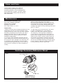
Cartridge Summary Reference Sheet
Order RP46463 to
Replace Cartridge.
Grey Upper Cap
V Notch
Adapter
Shorter Tab
T27
9

104438 Rev. B

Instrucciones para la
instalación del Accesorio de la
VálvulMultiChoice® con desviador
Manual para propietarios
T27 Modelos
Escriba el número del modelo aquí.
Puede necesitar
ESTA VALVULA cumple o excede las siguientes
normas: ASME A112.18.1 / CSA B125.1 y ASSE 1016
(Tipo -P- o -T-).
ADVERTENCIA: Este sistema/dispositivo debe
congurarse por el instalador para asegurar una
temperatura máximo segura. Cualquier cambio en el ajuste
puede aumentar la temperatura de salida por encima del
límite considerado seguro y puede dar lugar a quemaduras
por agua caliente.
AVISO PARA EL INSTALADOR: ¡ATENCIÓN! -Como
el instalador de esta válvula, es su responsabilidad
de INSTALAR y AJUSTAR correctamente esta válvula
según las instrucciones proporcionadas. Esta válvula
no se ajusta automáticamente a los cambios de
temperatura de entrada, por lo tanto, alguien debe
hacer los ajustes necesarios al Tope del Límite
Rotacional en el momento de la instalación y ajustes
adicionales pueden ser necesarios debido a cambios
estacionales de la temperatura del agua. USTED
DEBE informar al propietario/usuario de este requisito
siguiendo las instrucciones. Si usted o el dueño/
consumidor no está seguro de como hacer estos ajustes,
por favor consulte la página 6 y si aún tiene duda,
llámenos al 1-800-345-DELTA.
Después de la instalación y el ajuste, debe colocar su
nombre, nombre de la empresa y la fecha en que ajustó la
perilla de control de la temperatura a la etiqueta de
precaución proporcionada y aplique o pegue la etiqueta en
la parte trasera de la puerta del armario más cercano y la
etiqueta de advertencia al calentador de agua.
Deje esta hoja de instrucciones para referencia del
propietario /usuario.
ADVERTENCIA: Esta válvula termostática de baño está
diseñada para minimizar los efectos de los cambios
de temperatura del agua de salida debido a cambios
de presión y temperatura, causados habitualmente
por los lavaplatos, las lavadoras, los inodoros y otros
aparatos similares. Puede no ofrecer protección contra
las quemaduras por agua caliente cuando hay un fallo
de otros dispositivos para el control de temperatura
en otras partes del sistema de plomería, si el Tope del
Límite Rotacional no está congurado correctamente
o si se cambia la temperatura del agua caliente
después de realizar los ajustes o si el agua admisión
cambia debido a los cambios estacionales.
ADVERTENCIA: No instale un dispositivo de cierre en
cualquiera de las tuberías de salida de agua de esta
válvula. Cuando este tipo de dispositivo cierra el ujo
del agua, pueda aminorar el propósito de la válvula
para balancear las presiones del agua caliente y fría.
Rev. B07/13/2020 1
Tabla de contenido:
Garantía ............................................................................... Página 2
Instrucciones de instalación ................................................ Páginas 3 - 7
Limpieza y cuidado .............................................................. Página 9
Mantenimiento ...................................................................... Página 9
Hoja de referencia para el Cartucho .................................... Página 9
Para obtener piezas de repuesto adicionales, visite www.deltafaucet.com
104438

104438 Rev. B 2
Piezas y Acabado. Todas las piezas (excepto los componentes electrónicos y las pilas) y los acabados de los grifos Delta Faucet® comprados de vendedores autor-
izados por Delta están garantizados al consumidor comprador original de estar libres de defectos en material y fabricación durante el tiempo que el comprador original
sea propietario de la vivienda en la que el grifo/la llave de agua fue originalmente instalada. En el caso de los consumidores comerciales, (a) el período de garantía
es de diez (10) años para aplicaciones multifamiliares (apartamentos y condominios) y (b) cinco (5) años para todos las otras aplicaciones comerciales, en cada caso
a partir de la fecha de compra. Para los propósitos de esta garantía, el término “aplicación multifamiliar residencial” se refiere a la compra del grifo de un vendedor
autorizado por Delta por el comprador propietario que no vive en la vivienda residencial donde se instaló inicialmente la llave de agua, como en una unidad alquilada
o arrendada, o unidad o vivienda unifamiliar separada (dúplex o casas adosadas), o un condominio, edificio de apartamentos o centro de vivienda comunitaria. Las
siguientes instalaciones no se consideran aplicaciones multifamiliares residenciales, están excluidas de la garantía de 10 años y están sujetas a la garantía de cinco
años: instalaciones industriales, institucionales u otras instalaciones comerciales, como dormitorios, instalaciones de hotelería (hotel, motel o una alberga para estadías
prolongadas), aeropuerto, centro educativo, centro de atención de salud a corto o largo plazo (hospital, centro de rehabilitación, asilo de ancianos, unidad de vivienda
asistida o una unidad residencial de cuidado), espacio público o área común.
Piezas y acabados para grifos recertificados Delta®. Delta Faucet Company ofrece para la venta en deltafaucet.com llaves de agua/grifos recertificados Delta®. Todas
las piezas electrónicas (excepto las partes electrónicas y las pilas) y los acabados de estos grifos recertificados Delta® están garantizados al consumidor comprador
original de estar libres de defectos en material y fabricación durante diez (10) años a partir de la fecha de compra. Para los consumidores comerciales, el período de
garantía es por un (1) año a partir de la fecha de compra.
Piezas electrónicas. Las piezas electrónicas (excepto las pilas), si las hay, de las llaves de agua Delta® compradas de deltafaucet.com o vendedores autorizados por
Delta están garantizadas al consumidor comprador original de estar libres de defectos en material y fabricación durante cinco (5) años a partir de la fecha de compra o
para los consumidores comerciales, por un (1) año a partir de la fecha de compra. No se garantizan las pilas.
Lo que haremos. La compañía Delta Faucet Company reparará o reemplazará, sin costo alguno, durante el período de garantía aplicable (como descrito arriba)
cualquier pieza o acabado que demuestre ser defectuosa en material y/o fabricación bajo la instalación, el uso y el servicio normal. Si la reparación o el reemplazo no
es práctico, Delta Faucet Company puede optar por reembolsarle el precio de compra a cambio de la devolución del producto. Estos son sus remedios exclusivos.
Lo que no cubre. Debido a que Delta Faucet Company no puede controlar la calidad de los productos Delta vendidos por vendedores no autorizados, a menos que la
ley lo prohíba, esta garantía no cubre los productos Delta comprados a vendedores no autorizados.
No cubre cualquier gasto de labor incurrido por el comprador para reparar, reemplazar, instalar o desmontar este producto. Delta Faucet Company no es responsable por
cualquier daño al grifo que resulte del desgaste razonable, uso en el exterior, uso indebido, (incluyendo el uso del producto para una aplicación indebida), agua helada,
abuso, negligencia o la instalación, el mantenimiento o la reparación incorrecta, incluido el incumplimiento de las instrucciones de cuidado y limpieza correspondientes.
Delta Faucet Company recomienda el uso de los servicios de un plomero profesional para toda instalación y reparación de los grifos. También recomendamos que use
solo piezas de repuesto genuinas Delta®.
Lo que usted debe hacer para obtener servicio de garantía o piezas de repuesto. Se puede hacer un reclamo de la garantía y se pueden obtener piezas de repuesto
llamando al 1-877-345-DELTA (3358) o contactándonos por correo postal o electrónico como indicado (favor incluya el número del modelo y la fecha de compra):
En los Estados Unidos y México: En Canadá:
Delta Faucet Company Masco Canada Limited, Plumbing Group
Product Service Technical Service Centre
55 E. 111th Street 350 South Edgeware Road
Indianapolis, IN 46280 St. Thomas, Ontario, Canada N5P 4L1
Attention: Customer Solutions Attention: Customer Service
www.deltafaucet.com/service-parts/contact-us http://www.deltafaucet.ca/customersupport/assistance.html
El comprobante de compra (recibo de venta original) del comprador original debe ser disponible a Delta Faucet Company para todos los reclamos de garantía a menos
que el comprador haya registrado el producto en Delta Faucet Company o es un producto recertificado de Delta® comprado de deltafaucet.com. Esta garantía aplica
solo a las llaves de agua/grifos Delta® fabricados después de enero 1, 2019 e instalados en los Estados Unidos de América, Canadá y México.
La limitación de la duración de las garantías implícitas. Favor tomar nota que algunos estados/provincias (incluyendo Quebec) no permiten las limitaciones de
la duración de una garantía implícita por lo que las limitaciones a continuación puedan no aplicarle. HASTA EL ALCANCE MÁXIMO EN QUE LA LEY LO PERMITA,
CUALQUIER GARANTA IMPLCITA, INCLUIDAS LAS GARANTAS IMPLCITAS DE COMERCIABILIDAD Y DE IDONEIDAD PARA UN PROPSITO PARTICULAR,
ESTÁ LIMITADA AL PERODO LEGAL O A LA DURACIN DE ESTA GARANTA, LO QUE SEA MÁS CORTO.
Limitación de daños especiales, incidentales o consiguientes. Favor de tomar nota que algunos estados/provincias (incluyendo Quebec) no permiten la exclusión
o limitación de daños especiales, incidentales o consecuentes, por lo que estas limitaciones y exclusiones puedan no aplicarle. HASTA EL ALCANCE EN QUE LA
LEY LO PERMITA, ESTA GARANTA NO CUBRE Y DELTA FAUCET COMPANY NO SE HACE RESPONSABLE, POR NINGN DAO ESPECIAL, INCIDENTAL
O CONSIGUIENTE (INCLUYENDO LOS GASTOS DE LABOR PARA REPARAR, REEMPLAZAR, INSTALAR O DESMONTAR ESTE PRODUCTO), YA SEA EL
RESULTADO DEL INCUMPLIMIENTO DE CUALQUIER GARANTA EXPRESA O IMPLCITA, INCUMPLIMIENTO DE CONTRATO, AGRAVIO O DE OTRA MANERA.
DELTA FAUCET COMPANY NO SE RESPONSABILIZARÁ POR CUALQUIER DAO AL GRIFO QUE RESULTE DEL DESGASTE RAZONABLE, USO EN EL EXTERIOR
DE LA PROPIEDAD, USO INDEBIDO (INCLUYENDO EL USO DEL PRODUCTO PARA UNA APLICACIN INDEBIDA), AGUA HELADA, ABUSO, NEGLIGENCIA O
INSTALACIN O MANTENIMIENTO INADECUADO O INCORRECTO, INCLUYENDO EL NO SEGUIR LAS INSTRUCCIONES CORRESPONDIENTES PARA EL
CUIDADO, LA LIMPIEZA Y EL MANTENIMIENTO. Aviso para los residentes del estado de New Jersey: Las disposiciones de este documento tienen la intención de
aplicarse en la máxima medida permitida por las leyes del estado de New Jersey.
Derechos adicionales. Esta garantía le otorga derechos legales específicos y también puede tener otros derechos que varían de estado/provincia a estado/provincia.
Esta es la garantía escrita exclusiva de Delta Faucet Company y la garantía no es transferible.
Si tiene preguntas o dudas con respecto a nuestra garantía, por favor comuníquese con nosotros como se indica anteriormente o consulte nuestras Preguntas Frecuentes
Warranty FAQs en www.deltafaucet.com.
Garantía Limitada en las Llaves de Agua de Delta®
© 2020 Delta Faucet Company

104438 Rev. B
Instalación
1Instalación del cartucho
A. B.
Cierre los suministros de agua. Quite la tapa (1),
tuercas tapas (2) y las tapas de prueba (3) del cuerpo
de la tubería preliminar detrás de la pared (4).
Coloque una cubeta o recipiente pequeño sobre el
frente del cuerpo de la válvula y abra lentamente los
suministros de agua para eliminar cualquier residuo de
las líneas de suministro antes de instalar el cartucho.
Cierre otra vez el agua de suministro.
Introduzca el ensamble del adaptador (1) en
el cuerpo de la tubería preliminar interna (2).
Asegúrese de que el ensamble del adaptador está
colocado correctamente y está presionado hasta el
fondo dentro del cuerpo preliminar.
Gire el cartucho de la válvula (1) de forma que las
palabras "HOT SIDE" estén en el lado izquierdo.
Inserte el cartucho en el cuerpo de la tubería
preliminar. Asegúrese de que el dentado en el
cuerpo está totalmente encajado en la muesca en
el cuerpo de bronce (4). Introduzca la tuerca tapa
(5) en el cartucho y enrosque en el cuerpo. Apriete
bien, a mano y deslice la junta tórica (6) en el
casquete y el cartucho.
La aplicación de una ligera capa de grasa de
plomeros en las juntas tóricas puede facilitar el
montaje.
Solo para las excepciones de dorso con dorso o
instalaciones inversas (caliente en la derecha y fría
en la izquierda): Gire el cartucho de la válvula (1) de
forma que "HOT SIDE" aparece en la derecha.
Aplique lubricante de silicona en las tres juntas
tóricas mostradas arriba para facilitar la instalación
del cartucho y quitar del cuerpo de la tubería
preliminar.
Instale el cartucho asegurándose de que los
dentados están totalmente encajados en la ranura en
el cuerpo de la tubería preliminar (véase el paso C).
Deslice la junta tórica (3) y la tuerca tapa (4) sobre
el cartucho y enrosque en el cuerpo de la tubería
preliminar. Apriete con la mano de forma segura.
3
C. Instalación de dorso con dorso.
Instalación normal
(no se requieren cambios)
Reverse
Installation
Cold
Hot
1
2
3
4
2
3
1
2
1
2
3
4
53
4
2
4
31
6

104438 Rev. B
Instalación
2Instalación del cartucho de desvío
4
Para la instalación del casquete
Deslice la tuerca tapa (1) sobre el casquillo
desviador (2) y enrosque en el cuerpo de la
tubería preliminar.
Apriete a mano de forma segura.
B.
PARA LA INSTALACIÓN DEL CARTUCHO DE
DESVÍO:
Aplique lubricante de silicona a la junta tórica (2)
para facilitar la instalación del cartucho desviador
con el casquillo desviador (3). La aplicación
de una ligera capa de grasa de plomeros a las
juntas tóricas (4) puede facilitar el montaje.
Gire el cartucho desviador (1) asegurando que el
pasador de posicionamiento que está en la parte
inferior del cartucho se alinee con el agujero
correspondiente en el cuerpo de la tubería
preliminar.
Deslice el casquillo desviador (3) sobre la espiga
del cartucho alineando las lengüetas en el
casquillo desviador con ranuras en el cuerpo de
la tubería preliminar (5).
A.
3
1
5
2
1
2
5
4

104438 Rev. B
Instalación
3
5
Instalación del accesorio
Instalación del casquillo del accesorio
Deslice el casquillo del accesorio (1) sobre el
casquete (2), el cartucho y el cuerpo de la tubería
preliminar.
Asegúrese que el casquillo está correctamente
colocado sobre el frente del cartucho.
Instalación del chapetón
Para paredes acabadas de un grosor hasta 1 1/8".
Fije la placa posterior (1) al cuerpo de la unidad de
las tuberías preliminares (2) usando los 4 tornillos
(3) proporcionados.
Nota: asegúrese que la placa trasera está
colocada con el frente hacia adelante y con las
marcas visibles.
Deslice el chapetón o chapa de cubierta (4) sobre
el cartucho desviador, enrosque la tuerca del
accesorio (5) proporcionada en el casquillo del
desviador.
Nota: para instalaciones en paredes gruesas,
ordene el juego de piezas RP90543 para
sostener la pared acabada hasta de 2 1/8" de
grosor.
En supercies rugosas o desiguales, es necesario
aplicar masilla alrededor de la placa posterior
(1) para complementar el sello. No calafatee el
chapetón (4).
1
2
A. B. 12
5
4
Instale la manija para el control de; volumen
(1) con la palanca hacia abajo, luego gire a la
posición abierta. NO FIJE CON EL TORNILLO.
3
3
Muesca de goteo
7
6
C.
1

104438 Rev. B
Instalación
4
6
Instalación y ajuste del tope del límite rotacional
Coloque la perilla para el control de temperatura (1)
en la palanca de volumen y gire a la posición mixta
(si es necesario). NO FIJE CON EL TORNILLO.
Abra los suministros de agua; deje que el agua
uya hasta que esté lo más caliente/fría posible.
Coloque un termómetro en un vaso plástico, y
sostenga el vaso bajo el chorro de agua. Registre
la lectura de la temperatura.
Si la temperatura del agua está por encima de
120° F, retire y gire el tope (1) un diente hacia la
derecha por cada 4° F - 6° F (aproximadamente)
cambio en la temperatura. Si la temperatura del
agua es más fría que lo deseada, gire el tope
hacia la izquierda.
IMPORTANTE: La primera posición del Tope del
Límite Rotacional (el limitador) es la posición que
más restringe la rotación e la espiga y está en
el ajuste máximo hacia la derecha. De acuerdo
con los estándares de la industria, la temperatura
máxima permisible del agua que sale de la
válvula es 120° F. Esta temperatura puede variar
en su área local.
El Tope del Límite Rotacional puede requerir
reajuste si cambia la temperatura del agua
de entrada. Por ejemplo, durante el invierno,
la temperatura del agua fría es más fría de lo
que es durante el verano que podría resultar
en una variación de temperaturas de salida. La
temperatura típica para un baño o una ducha
confortable es entre 90o-110o F.
Hotter
Colder
Fije la perilla para el control de la temperatura (1)
con el tornillo (2). Para jar la tapa del control de
temperatura (3), vea el próximo paso (D).
Coloque a presión la tapa del control de temperatura sobre
el pomo del control de temperatura alineando primero la
lengüeta más pequeña (1) con la muesca para encajar
en la cubierta (2) ubicada en el pomo de temperatura.
Gire la lengúeta más grande (3) para que encaje con el
mecanismo de presión (4). Nota: Si requiere desarmar,
repita estos pasos en reverso, desencajando primero la
lengúeta más grande (3) del mecanismo de presión (4).
D.
42
1
3
B.
1
A.
1
C.
1
2
3

104438 Rev. B
Existe la posibilidad de lesión por escaldadura o de choque térmico resultante de un ujo cruzado
en el caso que la salida de la regadera/ducha está bloqueada o restringida (por ejemplo, pause el
control de la cabeza de la regadera/ducha). Asegúrese de apuntar la regadera/ducha alejado de
usted cuando vuelva a iniciar el ujo o instale las válvulas de retención de la entrada en ambas
líneas de suministro para evitar posibles lesiones.
7
Instalación del desviador de la manija
Instalación del desviador de la manija
Inserte la manija del desviador (1) sobre el
casquillo del accesorio (2). Usando una llave allen,
inserte el tornillo de jación/ajuste (3) en la manija
(1). Aplicando presión, inserte la tapa del tornillo
de ajuste (4) hasta que esté bien asentada.
6
Installation
5
2
1
3
4

104438 Rev. B 8
Hoja de referencia para la manija desviadora
2nd Position
2 ª Posición
2e position
3rd Position
3 ª posición
3e position
1st Position
1 ª posición
1ère position
2nd Position
2 ª Posición
2e position
3rd Position
3 ª posición
3e position
Outlet 1
Salida 1
Sortie 1
Outlet 2
Salida 2
Sortie 2
Outlet 3
Salida 3
Sortie 3
In / Entrada / Entrée
4th Position
4 ª posición
4e position
5th Position
5 ª posición
5e position
6th Position
6 ª posición
6e position
Water Flow For 3 Function Diverter / Flujo de agua para Desviadores de 3 posiciones / Écoulement
de l’eau pour les inverseurs à 3 positions
Water Flow For 6 Function Diverter / Flujo de agua para Desviadores de 6 posiciones / Écoulement
de l’eau pour les inverseurs à 6 positions
In / Entrada / Entrée In / Entrada / Entrée
In / Entrada / Entrée In / Entrada / Entrée In / Entrada / Entrée
Outlet 1
Salida 1
Sortie 1
Outlet 2
Salida 2
Sortie 2
Outlet 3
Salida 3
Sortie 3
Outlet 1
Salida 1
Sortie 1
Outlet 2
Salida 2
Sortie 2
Outlet 3
Salida 3
Sortie 3
Outlet 1
Salida 1
Sortie 1
Outlet 2
Salida 2
Sortie 2
Outlet 3
Salida 3
Sortie 3
Outlet 1
Salida 1
Sortie 1
Outlet 2
Salida 2
Sortie 2
Outlet 3
Salida 3
Sortie 3
Outlet 1
Salida 1
Sortie 1
Outlet 2
Salida 2
Sortie 2
Outlet 3
Salida 3
Sortie 3
Outlet 1
Salida 1
Sortie 1
Outlet 2
Salida 2
Sortie 2
Outlet 3
Salida 3
Sortie 3
Outlet 1
Salida 1
Sortie 1
Outlet 2
Salida 2
Sortie 2
Outlet 3
Salida 3
Sortie 3
Outlet 1
Salida 1
Sortie 1
Outlet 2
Salida 2
Sortie 2
Outlet 3
Salida 3
Sortie 3
In / Entrada / Entrée In / Entrada / Entrée In / Entrada / Entrée
Shared positions do not exist in non-shared cartridges.
Los ajustes o posiciones compartidas no existen en los cartuchos no-compartidos.
Comme leur nom l’indique, les cartouches sans position partagée ne comportent aucune position partagée.
Shared positions do not exist in non-shared cartridges.
Los ajustes o posiciones compartidas no existen en los cartuchos no-compartidos.
Comme leur nom l’indique, les cartouches sans position partagée ne comportent aucune position partagée.
1st Position
1 ª posición
1ère position

104438 Rev. B
Limpieza y Cuidado
Se debe tener cuidado con la limpieza de este producto.
Aunque su acabado es extremadamente resistente, puede
ser dañado por abrasivos o pulimentos ásperos. Para
limpiar, simplemente frote con un paño húmedo y seque con
una toalla suave.
Mantenimiento
Si hay ltración de agua desde la llave de agua/grifo de
la regadera:
CIERRE LOS SUMINISTROS DE AGUA. Reemplace la
válvula de cartucho o RP46463 RP32104
Vea Consejos útiles 1, 2, 3 y 4
Sugerencias útiles:
1. Antes de retirar el ensamble del cartucho de la válvula
para cualquier tarea de mantenimiento, asegúrese de anotar
la posición del tope de rotación en la tapa. El ensamble del
cartucho de la válvula siempre debe ser puesto de nuevo
en la misma posición. ¡CUIDESE! Después de que haya
terminado la instalación, abra la válvula para asegurarse de
que el agua FLUYE FRA PRIMERO.
2. Para extraer el cartucho de la válvula del cuerpo, cierre
el suministro de agua y retire la manija y la tuerca tapa. No
se debe quitar el cartucho de la válvula del cuerpo con un
destornillador. Coloque la manija en la espiga y gire hacia
la izquierda aproximadamente 1/4 de vuelta después que el
tope tenga contacto. Levante el cartucho de la válvula del
cuerpo.
Retire los asientos y resortes y reemplácelos.
Primero, coloque el diámetro mayor del resorte en el
bolsillo del asiento y luego presione el extremo cónico de
la junta sobre el resorte. Vuelva a ensamblar el cartucho
de la válvula y colóquelo de nuevo en el cuerpo, siguiendo
las instrucciones dadas en el punto 1.
3. Si el agua en su área contiene cal, óxido, arena u
otros contaminantes, su válvula de equilibrio de presión
requerirá una inspección periódica.
La frecuencia de la inspección dependerá de la cantidad
de contaminantes en el agua. Para inspeccionar el
cartucho de la válvula y quitarla y siga los pasos indicados
en la nota 1 anterior. Gire la válvula a la posición de
mezcla completa y agite el cartucho con fuerza.
Si hay un sonido de traqueteo, la unidad es funcional y se
puede volver a instalar siguiendo las instrucciones dadas
en la nota 1 anterior. Si no hay traqueteo, reemplace
el conjunto de la cubierta con la pieza de repuesto/RP
adecuada.
Hoja de resumen de referencia para el cartucho
Ordene RP46463 para
Reemplazar cartucho.
Tapa superior Gris
Muesca V
Adaptador
Lengüeta más corta
T27
9

104438 Rev. B
La page charge ...
La page charge ...
La page charge ...
La page charge ...
La page charge ...
La page charge ...
La page charge ...
La page charge ...
La page charge ...
La page charge ...
La page charge ...
La page charge ...
-
 1
1
-
 2
2
-
 3
3
-
 4
4
-
 5
5
-
 6
6
-
 7
7
-
 8
8
-
 9
9
-
 10
10
-
 11
11
-
 12
12
-
 13
13
-
 14
14
-
 15
15
-
 16
16
-
 17
17
-
 18
18
-
 19
19
-
 20
20
-
 21
21
-
 22
22
-
 23
23
-
 24
24
-
 25
25
-
 26
26
-
 27
27
-
 28
28
-
 29
29
-
 30
30
-
 31
31
-
 32
32


Delta Faucet T27833-BL Mode d'emploi
- Catégorie
- Articles sanitaires
- Taper
- Mode d'emploi
dans d''autres langues
- English: Delta Faucet T27833-BL User guide
- español: Delta Faucet T27833-BL Guía del usuario