Yamaha RS95 Le manuel du propriétaire
- Catégorie
- Batterie de musique
- Taper
- Le manuel du propriétaire

H
G
F
E
D
C
B
RS95
A
M
N
L
K
J
I

q
y
u
i
!0
!1
o
!2
tew r
H
I
G
w
!0
i
y
q
u
o
!1
!2
t
A
B
C
D
J
t
J
G
I
H
G
G
I
F
E

4
H
I
H
I
G
H
I
G
J
C
J
J
1
A
B
C
3
E
F
G
F
A
E
E
F
E
2
D
K
C
A
B
J
H
I
J
I
G
D
E
G
F
A
5
M

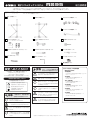
Electronic Drum Rack System
RS95
Assembly Instruction
Thank you for purchasing the Yamaha Electronic Drum Rack System RS95.
Before using, thoroughly read this assembly manual, and use this product safely and correctly.
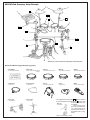
■
RS95 Rack Stand Parts
* Before assembling the rack stand, make sure all of the parts shown below are included.
Left Side Assembly (x1)
H
G
F
E
D
C
B
A
M
N
L
K
J
I
Center Pipe Assembly A (x1)
Center Pipe Assembly B (x1)
Right Side Assembly (x1)
Hex Rod Cylinder (x5)Module Holder Clamp (x1)
Assembly Instruction
(this sheet)
Tuning Key (x1)
Cable Band (x10)
Cymbal Holder (x2)
Felt Washer (x2)
Drum Pad Clamp (Long) (x3)Drum Pad Clamp (Short) (x1)
* Specifications are subject to change without notice.
Before using, please read this “Assembly Instruction” sheet,
and use this product in a safe and proper manner.
Especially for children, parents or an instructor should teach the
children the proper manner in which to use the device.
Caution (including danger, or warning). This mark indicates
cautions in which you should pay close attention to.
Acts indicated with this icon are prohibited and should not
be attempted.
This icon indicates acts that you are urged to follow.
Module Holder (x1)
(4 screws included)
* Specifications are subject to change without notice.
Always set the instrument on a flat and solid surface.
Placement on a sloping, unstable surface or on steps
may result in the instrument being unstable and over-
turning.
Make sure all bolts are tightened firmly. Loose bolts
may result in the rack overturning or parts dropping
causing injury.
When adjusting the height or angle, do not suddenly
loosen the bolt. The pad may drop, the rack or pipes
may slip, pinching or causing injury to hands or fingers.
Do not sit or step on the rack. The rack may overturn
or be damaged resulting in injury.
Please be careful when children are close to or touch-
ing the product. The product has many pipes and arms
so careless movement around the product may result
in injury.
When setting the pads and modules, please pay close
attention in regards to the handling and setting of
cables. Feet may become entangled in the cables re-
sulting in falls.
If this symbol is ignored and the equipment is
used improperly, fatal injury to persons or se-
rious damage could occur.
Do not put your hands or feet under the foot pedal or
foot switch. They may be pinched resulting in injury.
Watch your fingers when adjusting clamps. They may
become pinched resulting in injury.
Be careful around pipe ends, inside the pipe and screw
ends. Metal shavings, etc. may injure your fingers.
Do not attach acoustic drums to the electronic drum
rack. Clamps may be damaged and drums may drop,
causing injury.
If this symbol is ignored and the equipment is
used improperly, there is a danger of injury to
persons handling the equipment, and material
damage could occur.
CAUTION
WARNING

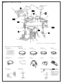
● Pad and Drum Trigger Grouping (option)
w
!0
i
y
q
u
o
!1
!2
t
A
B
C
D
J
t
J
G
I
H
G
G
I
F
E
qDTXTREME
Drum Trigger Module
tRHP80
Real Head Pad (8inch)
rRHP100
Real Head Pad (10inch)
eRHP120
Real Head Pad (12inch)
yTP80S/TP80
Drum Pad
!2Snare Stand
*SS-642 etc.
!1Foot Pedal
*DFP-880 etc.
uPCY80S/PCY80
Cymbal Pad
oPCY10
Trigger Pad
iKP120
Real Head Kick Pad
!0HH60
Hi-hat Control Pedal
TPCL100
Tom Holder
■
RS95+Pad Grouping: Setup Example
* Please use a snare stand for setting the snare drum pad.
wRHP120SD
Snare Type Real Head Pad
(12inch)
* The supplied Drum Pad Clamp
H
I
can be attached
to the RS95 and the Hex Rod Cylinder
G
can be used
to attach lighter pads up to
the RHP80.
When a large, heavy
pad, such as the RHP100/
120 is to be attached, we
recommend the use of the
tom holder TPCL100 (op-
tional).
Includes Holder Clamp Assembly.

■
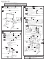
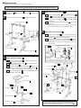
RS95 Assembly
* A screw driver (+ or -) is necessary to complete the assembly.
1
3
2
Center Pipe Assembly A
C
Tighten
Right Side Assembly
B
Center Pipe
Assembly B
D
Left Side Assembly
A
DTXTREME
Step 3-3
Step 3-2
Step 3-1
Tighten
Left Side Assembly
A
Module Holder Clamp
F
Hex Rod Cylinder
G
Module Holder
E
Step 3-4
Please make sure that the fixing bolts on each part, such as clamps, pads, etc. are firmly tightened.
Bolts that are too tight or too loose may result in damage to the part or the part dropping. Please use caution.
Attach the Center Pipe Assembly A
C
to the upright pipes of the Left
Side Assembly
A
and the Right Side Assembly
B
, and tighten the
wing bolts.
Attach the Center Pipe Assembly B
D
, and tighten the wing bolts.
Attach the Module Holder
E
3-1 Insert the Hex Rod Cylinder
G
into the Module Holder Clamp
F
, and tighten the fixing screw.
3-2 Attach the Module Holder Clamp
F
to the upright pipe on the
Left Side Assembly
A
.
3-3 Attach the DTXTREME to the Module Holder
E
. Using a screw
driver and the supplied screws, attach the Module Holder
E
to
the screw holes on the bottom of the DTXTREME.
3-4 Attach the Module Holder
E
, with the DTXTREME attached, to
the Module Holder Clamp
F
.
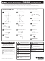
4
5
After the above assembly is complete, set the Kick Pad, Hi-Hat Control
pedal, etc. into position and connect the necessary cables. To keep
cable out of the way while playing, use the supplied Cable Bands
K
to
hold the cables to the rack system's pipes.
Tilter
Cymbal Pad
PCY10
Step 4-2
Step 5-2
Cymbal Pad
Felt (Small)*
Felt (Large)*
Washer*
Step 4-1
Step 5-1
Step 4-3
Cymbal Holder
J
Hex Rod Cylinder
G
Cymbal Holder
J
Drum Pad Clamp
(Short)
H
Drum Pad Clamp
(Long)
I
Drum Pad Clamp
(Long)
I
Tighten
Attach the Drum Pad Clamps
H
I
4-1 Insert the Hex Rod Cylinders
G
into the Drum Pad Clamps
H
and
I
, and tighten the fixing screws.
4-2 Attach the Drum Pad Clamp (short)
H
to the floor tom position.
Attach the Drum Pad Clamps (long)
I
to the high-hat and tom-
tom positions.
4-3 Attach the drum pad to the Hex Rod Cylinder
G
, align the pad
and secure.
When a large pad, such as the RHP100/120 is used, we recom-
mend that the tom holder TPCL100 (optional) be used.
Attach the Cymbal Holders
J
5-1 Insert the Cymbal Holders
J
into the cymbal holder clamps that
are positioned on the left and right sides of the Center Pipe
Assembly A
C
, and secure with the wing bolts.
5-2 Attach the cymbal pads to the Cymbal Holders
J
, align the
pads and secure. (Refer to the cymbal’s Owner’s Manual.) Also,
when the PCY10 is used, please use the parts shown in the
diagram below.
● When the PCY10 is used.
Anti-swivel brace
(supplied with the
PCY80/80S)
Change to the felt
washer
M
.
* The * indicates parts supplied with the PCY10.
* It is not necessary to use the tilter that is supplied with the PCY10.
-
 1
1
-
 2
2
-
 3
3
-
 4
4
-
 5
5
-
 6
6


Yamaha RS95 Le manuel du propriétaire
- Catégorie
- Batterie de musique
- Taper
- Le manuel du propriétaire
dans d''autres langues
- italiano: Yamaha RS95 Manuale del proprietario
- English: Yamaha RS95 Owner's manual
- español: Yamaha RS95 El manual del propietario
- Deutsch: Yamaha RS95 Bedienungsanleitung
- русский: Yamaha RS95 Инструкция по применению
- Nederlands: Yamaha RS95 de handleiding
- português: Yamaha RS95 Manual do proprietário
- dansk: Yamaha RS95 Brugervejledning
- polski: Yamaha RS95 Instrukcja obsługi
- čeština: Yamaha RS95 Návod k obsluze
- svenska: Yamaha RS95 Bruksanvisning
- 日本語: Yamaha RS95 取扱説明書
- Türkçe: Yamaha RS95 El kitabı
- română: Yamaha RS95 Manualul proprietarului
Documents connexes
-
Yamaha RS-80 Le manuel du propriétaire
-
-
-
-
-
-
-
-
-