CARLO GAVAZZI CLD1EA1CM24 Manuel utilisateur
- Taper
- Manuel utilisateur

1-point Basic level controller
Type CL with potentiometer and Time Control
CLD1EA1CM24
User Manual
Bedienungsanleitung
Manuel de l’utilisateur
Manual del Usuario
Manuale d’istruzione
Brugervejledning
μ-Processor based level controller for liquids with a wide sensitivity
range from 5 KΩ to 150 KΩ.
One probe level control with built in ON
or OFF time delay for filling or emptying applications. The time delay
can be set from 1 to 30 seconds.
• Conductive level controller
• Sensitivity adjustment 5 KΩ to 150 KΩ
• For filling or emptying applications
• Low-voltage AC electrodes
• Easy installation on DIN rails 17.5 mm
• Rated operational voltage: 24 VAC/DC
• Output 8A/250 VAC SPST relay
• LED indication for: Output ON, Power ON
Product Description GB
Specifications
Rated operational voltage (U
B
)
Supply Class 2
Pin A1 & Pin2 24 19.2 to 28.8 VAC/DC
Rated insulation voltage <2.0 kVAC (rms)
Rated impulse withstand
Voltage 4 kV (1.2/50 µs) (line/neutral)
Relay Rating (AgCdO) µ (micro gap)
Resistive loads AC1 8A / 250 VAC
DC1 1A / 250 VDC or
10 A / 25 VDC
Small induc. Loads
AC11 0,4 A/ 250 VAC
DC13 0,4 A/ 30VDC
Mechanical life (typical) > 30 x 10
6
opr @ 18’000 imp/h
Electrical life (typical) AC1 >250’000 opr
Level probe supply Max. 5 VAC
Level probe current Max. 2 mA
Sensitivity 5KΩ to 150KΩ, CF ≤ 2.2 nF
Factory settings 150KΩ
Operating frequency (f) Relay output 0.5 HZ
Degree of protection IP 20 (IEC 60529, 60947-1)
Temperature
Operating -20º to +50ºC (-4º to + 122ºF)
Storage -50º to +85ºC (-58º to +185ºF)
Approvals
UL cURs UL508, UL325,
CSA CSA-C22.2 No.247
CE marking Yes
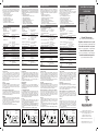
Conductive Level Controller
Sensitivity
1
2
3
10
4
56
8
7
9
Fill Empty
Off
On
OnOff
Off
On
OnOff
Delay
1
2
3
10
4
56
8
7
9
30sec.
Y2 11 14
Y1 A1 A2
Wiring Diagram / Shaltplan / Diagramme de
câblage / Diagrama de conexiones / Schema
elettronico / Forbindelsesdiagram
Connection cable
2 conductor PVC cable, normally screened. Cable length: max.
100 m. The resistance between the cores and the ground must
be at least 150K. Normally, it is re commended to use a screened
cable between probe and controller, e.g. where the cable is
placed in parallel to the load cables (mains). The screen has to be
connected to Y2 (reference).
The filling or emptying process operate around one single electrode
and a time control circuit.
Causions
Overrunning of tank filling
Causions must be taken to assure that the tank cannot overrun.
Factors that have to be considered are the pump performance,
the rate of discharge from the tank, the position of the single level
electrode and the time delay.
Prevent dry running of pump on emptying
Care must be taken to ensure that the pump cannot run dry. Similar
considerations must be given as mentioned above. Specifically
keeping the time delay to a minimum will minimize this risk, but
again, it will increase the switching rate.
Example 1
The diagram shows the level control connected as filling or emptying
control. The re lay react to the low alternating current created when
the electrodes are in contact with the liquid.
The reference (Ref) must be connected to the container or if the
container consists of a non-conductive mater ial, to an additional
electrode. (To be connected to pin Y2).
(In the diagram this electrode is shown by the dotted line).
Mode of Operation
REF
Hi
Filling or Emptying
A1
A2
Y1
Y2
(PE)
14
11
(+)
(-)
Example 1
(Din-rail)
Mikroprozessor-gesteuerter Füllstandsregler für Flüssigkeiten, breiter
Empfindlichkeitsbereich von 5 kΩ bis 150 kΩ. Relais zur konduktiven
Niveauüberwachung mit Ein - und Ausschaltverzögerung für Füllen
oder Entleeren. Die Zeitverzögerung kann zwischen 1 und 30 Sekunden
eingestellt werden.
• Konduktiver Füllstandsregler
• Empfindlichkeit einstellbar von 5 kΩ bis 150 kΩ
• Für Füll- und Entleer-Anlagen
• AC-Niederspannungselektroden
• Einfacher Einbau auf DIN-Schiene, 17,5 mm
• Nennbetriebsspannung: 24 VAC/DC
• Ausgang 8 A / 250 VAC, SPST-Relais
• LED-Anzeige für: Ausgang EIN, Gerät EIN
Produktbeschreibung D
Eigenschaften
Nennbetriebsspannung (U
B
)
Klasse 2
Pin A1 & A2 24 19,2 bis 28,8 VAC/DC
Nennisolierspannung <2,0 kVAC (eff.)
Nennstehstoßspannung 4 kV (1,2/50 µs) (Leiter/Neutral)
Relais (AgCdO) µ (Mikrokontakt)
Ohmsche Last AC1 8 A / 250 VAC (2500 VA)
DC1 1 A / 250 VDC (250 W) bzw.
10 A / 25 VDC (250 W)
Induk. Kleinlast AC15 0,4 A250 VAC
DC13 0,4 A / 30 VDC
Mechanische Lebensdauer (typ.) ≥ 30 x 10
6
Schaltzyklen
bei 18.000 Imp./h
Elektrische Lebensdauer (typ.)
AC1 > 250.000 Schaltzyklen
Leistung Füllstandssensor Max. 5 VAC
Strom Füllstandssensor Max. 2 mA
Empfindlichkeit 5 kΩ bis 150 kΩ, CF ≤ 2,2 nF
Werkseinstellungen 150KΩ
Max. Betriebsfrequenz (f) Relaisausgang 0,5 Hz
Schutzart IP 20 (IEC 60529, 60947-1)
Temperatur
Betrieb -20 bis +50 ºC
Lagerung -50 bis +85 ºC
UL-Zulassungen
UL cURs UL508, UL325,
CSA CSA-C22.2 Nr. 247
CE-Kennzeichnung Ja
Anschlusskabel
PVC-Kabel (2 Adern), normal geschirmt. Leitungslänge max. 100
m. Der Widerstand zwischen Leiter und Masse muss mindestens
150 k betragen. Das Kabel zwischen Fühlerkopf und Regler sollte
abgeschirmt sein (insbesondere bei Verlegung direkt neben dem
Stromversorgungskabel). Die Abschirmung ist an Y2 anzuschließen
(Referenz).
Füllen und Entleeren werden von einer einzigen Elektrode in
Kombination mit einem Zeitgeber gesteuert.
Wichtige Hinweise
Überlaufschutz
Der Überlaufschutz ist durch zusätzliche Maßnahmen zu
gewährleisten. Dabei sind folgende Faktoren zu berücksichtigen:
Pumpleistung, Abflussmenge, Position der Messelektrode und
Ansprechverzögerung.
Trockenlaufschutz der Pumpe
Es sind Maßnahmen gegen das Trockenlaufen der Pumpe beim
Entleeren durchzuführen. Dabei sind ähnliche Faktoren wie die
vorstehend genannten zu berücksichtigen. Insbesondere die
Ansprechverzögerung sollte auf ein Minimum verkürzt werden. Dabei
ist jedoch zu beachten, dass sich die Anzahl der Schaltzyklen erhöht,
wenn die Verzögerungszeit verkürzt wird.
Beispiel 1
Der Schaltplan zeigt die Füllstandsmessung beim Füllen und
Entleeren. Das Relais spricht auf den Niederwechselstrom an, der
zwischen den Elektroden in der Flüssigkeit fließt.
Der Referenzpunkt (Ref) muss mit dem Behälter elektrisch leitend
verbunden sein; bei Behältern aus nicht leitfähigem Material muss er
mit einer Zusatzelektrode verbunden werden. (Der Anschluss erfolgt
an Pin
Y2
).
Im Diagramm ist die Elektrode durch eine Punktlinie dargestellt.
Funktionsweise
Régulateur de niveau basé sur le processeur µ pour liquides avec
une large plage de sensibilité de 5 KΩ à 150 KΩ. Un contrôleur de
niveau intégrant une temporisation ON ou OFF pour les applications
de remplissage ou de vidange. La temporisation est réglable de 1 à
30 secondes.
• Régulateur de niveau conducteur
• Réglage de sensibilité 5 KΩ à 150 KΩ
• Pour applications de remplissage ou de vidange
• Électrodes CA à faible tension
• Installation facile sur les rails DIN 17,5 mm
• Tension de fonctionnement nominale : 24 VCA/CC
• Sortie 8A/250 relais VCA SPST
• Indication DEL pour : Sortie MARCHE, puissance MARCHE
Description du produit F
Spécifications
Tension de fonctionnement nominale (U
B
)
Classe d’alimentation 2
Broches A1 et A2 24 19,2 à 28,8 VCA/CC
Tension d’isolation nominale <2,0 kVCA (rms)
Tension nominale de résistance
impulsion 4 kV (1,2/50 µs) (ligne/neutre)
Régime nominal du relais (AgCdO) µ (espace micro)
Charges résistives CA1 8 A / 250 VCA (2500 VA)
CC1 1 A / 250 VCC (250 W) ou
10 A / 25 VCC (250 W)
Petites charges inductives CA15 0,4 A250 VCA
CC13 0,4 A / 30 VCC
Longévité mécanique (typique) ≥ 30 x 10
6
opérations
@ 18 000 imp/h
Longévité électrique (typique) CA1 > 250 000 opérations
Alimentation sonde de niveau Max. 5 VCA
Courant sonde de niveau Max. 2 mA
Sensibilité 5 KΩ à 150 KΩ, CF ≤ 2,2 nF
Réglage d’usine 150KΩ
Fréquence de fonctionnement (f) max
Sortie relais 0,5 HZ
Degré de protection IP 20 (IEC 60529, 60947-1)
Température
Fonctionnement -20º à +50ºC
Stockage -50º à +85ºC
Certification
UL cURs UL508, UL325,
CSA CSA-C22,2 No.247
Marquage CE Oui
Câble de connexion
Câble PVC à 2 conducteurs, normalement blindé. Longueur du câble
: max. 100 m. La résistance entre les noyaux et la terre doit être d’au
moins de 150K. Normalement, il est recommandé d’utiliser un câble
blindé entre la sonde et le régulateur, par exemple là où le câble est
placé en parallèle aux câbles de charge (réseau électrique). Le câble
blindé doit être connecté à Y2 (référence).
Le processus de remplissage ou de vidange fonctionne autour d’une
seule électrode et un circuit de régulation du temps.
Précautions
Dépassement du remplissage du réservoir
Des précautions doivent être prises pour éviter un trop-plein du
réservoir. Les facteurs qui doivent être pris en compte sont les
caractéristiques de la pompe, le débit de sortie depuis le réservoir, la
position de électrode de niveau unique et la temporisation
Eviter un fonctionnement à sec de la pompe lors de la vidange
Des précautions doivent être prises pour éviter que la pompe ne
tourne à sec. Des mesures similaires doivent êtres prises, comme
indiqué ci-dessus. Spécifiquement, le maintien d’une temporisation
minimale permettra de minimiser ce risque, mais une fois encore,
cela augmentera le débit de commutation.
Exemple 1
Le diagramme indique le régulateur de niveau connecté comme
régulateur de remplissage ou de vidange. Le relais réagit au faible
courant alternatif créé lorsque les électrodes sont en contact avec
le liquide.
La référence (Réf) doit être connectée au conteneur, ou si le conteneur
est un matériel non conducteur, à une électrode additionnelle. (À
connecter à la broche
Y2
).
(Dans le diagramme cette électrode est indiquée par la ligne pointillée).
Mode de fonctionnement
Control de nivel basado en microprocesador para líquidos con un
amplio rango de sensibilidad de 5 KΩ a 150 KΩ.
Control de nivel con una sonda con retardo de tiempo ON/OFF
incorporado, para aplicaciones de llenado o vaciado. El retardo de
tiempo puede ajustarse de 1 a 30 segundos.
• Controlador de nivel conductivo
• Ajuste de sensibilidad de 5 KΩ a 150 KΩ
• Para aplicaciones de llenado y vaciado
• Electrodos de CA de baja tensión
• Fácil instalación a carril DIN de 17,5 mm
• Tensión nominal de funcionamiento: 24 VCA/CC
• Salida de relé: 8A/250VCA, SPST
• Indicación LED para: Salida y alimentación conectadas
Descripción del producto E
Especificaciones
Tensión nominal
de funcionamiento (U
B
)
Clase de alimentación 2
Patillas A1 y A2 24 19,2 a 28,8 VCA/CC
Tensión nominal de aislamiento <2,0 kVCA (rms)
Impulso de tensión nominal
soportada 4 kV (1,2/50 µs) (línea-neutro)
Clasificación de contactos (AgCdO) µ (microgap)
Cargas resistivas AC1 8 A / 250 VCA (2500 VA)
DC1 1 A / 250 VCC (250 W) o
10 A / 25 VCC (250 W)
Pequeñas cargas inductivas AC15 0,4 A / 250 VCA
DC13 0,4 A / 30 VCC
Vida útil mecánica (típica) ≥ 30 x 10
6
operaciones
@ 18.000 pulsos/h
Vida útil eléctrica (típica) AC1 > 250.000 operaciones
Alimentación de la sonda de nivel Máx. 5 VCA
Intensidad en la sonda de nivel Máx. 2 mA
Sensibilidad 5 KΩ a 150 KΩ, CF = 2,2 nF
Ajuste de fábrica 150 KΩ
Frecuencia de funcionamiento (f)
máx. Salida de relé 0,5 Hz
Grado de protección IP 20 (IEC 60529, 60947-1)
Temperatura
Funcionamiento -20º a +50ºC
Almacenamiento -50º a +85ºC
Homologación
UL cURs UL508, UL325,
CSA CSA-C22.2 N.247
Marca CE Sí
Cable de conexión
Cable PVC de 2 conductores, normalmente apantallado. Longitud
del cable: máx. 100 m. La resistencia entre el hilo conductor y
tierra debe ser al menos de 150K. Normal mente, se recomienda
utilizar un cable apantallado entre la sonda y el relé, por ejemplo, si
el cable se coloca en paralelo con los cables de potencia (red). El
apantallamiento tiene que conectarse a Y2 (referencia).
El proceso de llenado o vaciado funciona en torno a un único
electrodo y a un circuito de control de tiempo.
Precauciones:
Desbordamiento del llenado del depósito
Hay que tomar precauciones para asegurar que el depósito no
se desborde. Los factores a considerar son el rendimiento de la
bomba, la velocidad de descarga del depósito, la posición del único
electrodo de nivel y el retardo de tiempo.
Evitar el funcionamiento en seco de la bomba en el vaciado
Hay que asegurarse de que la bomba no funcione en seco,
tomando precauciones similares a las mencionadas anteriormente.
En concreto, manteniendo el retardo de tiempo en un nivel
mínimo, se reducen los riesgos, aunque aumentará la velocidad de
conmutación.
Ejemplo 1
El diagrama muestra el control de nivel conectado como control
de llenado o vaciado. El relé reacciona a la corriente alterna baja
ge-nerada cuando los electrodos están en contacto con el líquido.
La referencia (Ref) debe conectarse al depósito, o si el depósito está
fabricado con un material no conductor, a un electrodo adicional.
(Se conectará a la patilla Y2).
(En el diagrama, dicho electrodo se indica con una línea de puntos).
Modo de funcionamiento
Einpunkt-Füllstandsregler
Typ CL mit Potentiometer und Zeitsteuerung
Régulateur du niveau de base à 1 point
Type CL avec potentiométre et règulateur de temps
Controlador de nivel básico en 1 punto
Modelo CL con potenciómetro y control de tiempo
Controllo di livello base a 1 punto
Tipo CL con potenziometro e controllo temporale
1-punkts standardniveaustyreenhed
Type CL med potentiometer og timer
REF
Hi
Filling or Emptying
A1
A2
Y1
Y2
(PE)
14
11
(+)
(-)
Beispiel 1
(DIN-Schiene)
Füllen oder
Entleeren
REF
Hi
Filling or Emptying
A1
A2
Y1
Y2
(PE)
14
11
(+)
(-)
Exemple 1
(Rail Din)
Remplissage ou
vidange
REF
Hi
Filling or Emptying
A1
A2
Y1
Y2
(PE)
14
11
(+)
(-)
Ejemplo 1
(Carril DIN)
Llenado o
vaciado
15-029-737
MAN CLD1EA1CM24 MUL rev.14 - 02.2019
Specifications are subject to change without notice
CARLO GAVAZZI
www.gavazziautomation.com
Certified in accordance with ISO 9001
Gerätehersteller mit dem ISO 9001/EN 29 001 Zertifikat
Une société qualifiée selon ISO 9001
Empresa que cumple con ISO 9001
Certificato in conformità con l’IS0 9001
Kvalificeret i overensstemmelse med ISO 9001

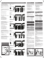
Operation Diagram / Schaltbild / Diagramme de fonctionnement / Diagrama de funcionamiento / Diagramma di funzionamento / Funktionsdiagram
T
Y1
Y2
T
TT
Power supply ON
Filling with ON-delay (prevent overflow)
(Hi-probe)
Level
Output ON
Fill
Off
On
OnOff
Off
On
OnOff
Empty
Time
[11-14]
T
Y1
Y2
TT
T
Power supply ON
Filling with Off-delay
(Lo-probe)
Level
Output ON [11-14]
Fill
Off
On
OnOff
Off
On
OnOff
Empty
Time
TT
Y1
Y2
TTT
TT
Power supply ON
Filling with ON and Off-delay
(Center-probe)
Level
Output ON [11-14]
Fill
Off
On
OnOff
Off
On
OnOff
Empty
Time
T
TT
Y1
Y2
T
Power supply ON
Emptying with Off-delay
(Hi-probe)
Level
Output ON [11-14]
Fill
Off
On
OnOff
Off
On
OnOff
Empty
Time
T TTT
Y1
Y2
Power supply ON
Emptying with ON-delay (Prevent dry run)
(Lo-probe)
Level
Output ON [11-14]
Fill
Off
On
OnOff
Off
On
OnOff
Empty
Time
TTTTT
TT
Y1
Y2
Power supply ON
Emptying with ON and Off-delay
(Center-probe)
Level
Output ON [11-14]
Fill
Off
On
OnOff
Off
On
OnOff
Empty
Time
Controllore di livello basato su processore µ per liquidi con una vasta
gamma di sensibilità da 5 KΩ a 150 KΩ. Controllo di livello con ritardo
ON / OFF integrato, per applicazioni di riempimento o svuotamento.Il
ritardo può essere impostato da 1 a 30 secondi.
• Controllore di livello conduttivo
• Regolazione della sensibilità da 5KΩ a 150 KΩ
• Per applicazioni di riempimento o svuotamento
• Elettrodi CA a bassa tensione
• Facile installazione su guide DIN da 17.5 mm
• Tensione operativa nominale: 24 VCA/CC
• Uscita a relé SPST 8A/250 VCA
• Indicazione LED per: Uscita ON, Alimentazione ON
Descrizione del prodotto I
Specifiche
Tensione nominale operativa (U
B
)
Classe di alimentazione 2
Pin A1 & A2 24 da 19,2 a 28,8 VCA/CC
Tensione di isolamento nominale <2,0 kVCA (rms)
Tensione nominale di tenuta alle
scariche a impulso 4 kV (1.2/50 µs) (linea/neutro)
Classificazione relé (AgCdO) µ (micro gap)
Carichi resistivi CA1 8 A / 250 VCA (2500 VA)
CC1 1 A / 250 VCC (250 W) o
10 A / 25 VCC (250 W)
Piccoli carichi induttivi CA15 0,4 A250 VCA
CC13 0,4 A / 30 VCC
Durata meccanica (tipica) ≥ 30 x 10
6
operazioni
@ 18.000 imp/h
Durata elettrica (tipica) CA1 > 250.000 operazioni
Alimentazione sonda di livello Massimo 5 VCA
Corrente sonda di livello Massimo 2 mA
Sensibilità da 5 KΩ a 150 KΩ, CF ≤ 2,2 nF
Impostazione predefinita 150KΩ
Frequenza operativa (f) massima Uscita a relé 0,5 Hz
Grado di protezione IP 20 (CEI 60529, 60947-1)
Temperatura
Operativa da -20º a +50ºC
Conservazione da -50º a +85ºC
Approvazioni
UL cURs UL508, UL325,
CSA CSA-C22,2 No.247
Marchio CE Sì
Cavo di collegamento
cavo a 2 conduttori in PVC, normalmente schermato. Lunghezza
del cavo: massimo 100 m. La resistenza tra il nucleo e la terra
deve essere almeno 150K. Normalmente, si consiglia di utilizzare
un cavo schermato tra sonda e controllore, ad esempio nel caso in
cui il cavo venga posizionato in parallelo rispetto ai cavi di carico
(di alimentazione). La schermatura deve essere collegata a Y2
(riferimento).
Il processo di riempimento o svuotamento avviene intorno a un solo
elettrodo e a un circuito di controllo temporale.
Precauzioni
Riempimento eccessivo del serbatoio
È necessario adottare precauzioni per garantire che il serbatoio non
straripi. I fattori da considerare sono le prestazioni della pompa, la
velocità di scarico dal serbatoio, la posizione del singolo elettrodo
di livello e il ritardo.
Prevenzione del funzionamento a secco della pompa dopo lo
svuotamento
È necessario adottare precauzioni in modo tale che la pompa non
possa funzionare a secco. Devono fatte considerazioni simili a
quanto sopra menzionato. In particolare, mantenendo il ritardo al
minimo si riduce tale rischio, ma dopotutto ciò aumenterebbe la
velocità di commutazione.
Esempio 1
Il diagramma mostra il controllo di livello connesso come controllo
di riempimento o svuotamento. Il relè reagisce alla corrente alternata
bassa creata quando gli elettrodi sono a contatto con il liquido.
Il riferimento (Re) deve essere collegato al contenitore o se nel
contenitore si trova un materiale non conduttivo, a un elettrodo
aggiuntivo. (Da collegare al pin
Y2
).
(Nel diagramma questo elettrodo è indicato con la linea tratteggiata.)
Modalità di funzionamento
REF
Hi
Filling or Emptying
A1
A2
Y1
Y2
(PE)
14
11
(+)
(-)
Esempio 1
(guida DIN)
Mikroprocessorbaseret niv-eaustyreenhed til væsker med et bredt
følsomhedsområde 5 KΩ til 150 KΩ. 1-føler niveaustyring med
indbygget ind- eller udkoblingsforsinkelse til påfyldnings- eller
tømningsanlæg. Tidsforsinkel sen kan sættes til 1 - 30 se kunder.
• Ledende niveaustyreenhed
• Justering af følsomhed 5 KΩ til 150 KΩ
• Til påfyldnings- eller tømningsanlæg
• Lavspændingselektroder (AC)
• Nem installation på DIN-skinner 17,5 mm
• Nominelt spændingsområde: 24 V AC/DC
• Output 8A/250 VAC SPST relay
• Lysdiodeindikation for: Udgang aktiveret og Power aktiveret
Produktbeskrivelse DK
Specifikationer
Nominel spændingsforsyning (U
B
)
Forsyningsklasse 2
Ben A1 & A2 24 19,2 til 28,8 V AC / DC
Nominel isoleringsspænding < 2,0 kV AC (rms)
Nominel stødspænding 4 kV (1,2/50 µs) (fase/neutral)
Relæbelastning (AgCdO) µ (mikrokontakt)
Ohmske belastninger AC1 8 A / 250 V AC (2500 VA)
DC1 1 A / 250 V DC (250 W) eller
10 A / 25 V DC (250 W)
Små induk. belastninger AC15 0,4 A 250 VAC
DC13 0,4 A / 30 VDC
Mekanisk levetid (typisk) ≥ 30 x 10
6
aktiveringer
@ 18.000 impulser/time
Elektrisk levetid (typisk) AC1 > 250.000 aktiveringer
Niveaufølerforsyning Maks. 5 VAC
Niveaufølerstrøm Maks. 2 mA
Følsomhed 5 KΩ til 150 KΩ, CF ≤ 2,2 nF
Fabriksindstilling 150KΩ
Tastefrekvens (f) maks.
Relæudgang 0,5 Hz
Tæthedsgrad IP 20 (IEC 60529, 60947-1)
Temperatur
Drift -20º til +50ºC
Lager -50º til +85ºC
Godkendelser
UL cURs UL508, UL325,
CSA CSA-C22,2 Nr. 247
CE-mærkning Yes
Tilslutningskabel
2- eller 3-leder pvc-kabel, normalt skærmet. Kabellængde: maks.
100 m. Modstanden mellem kernerne og jord skal være mindst
150K. Normalt anbefales det at bruge et skærmet kabel mellem
føler og styreenhed, f.eks. hvis kablet er placeret parallelt med
belastningskablerne (strømforsyning). Afskærm ningen skal tilsluttes
Y2 (reference).
Påfyldnings- eller tømnings processen styres af en en kelt elektrode
og en timer.
Forsigtighed
Overløb ved påfyldning
Der bør træffes forholdsreg ler mod at tanken løber over.
Følgende faktorer skal tages i betragtning: pumpens yde evne,
udtømningshastighed fra tanken, placering af en-k elt niveau-
elektroden og timerindstillingen.
Undgå at pumpen kører tør ved tømning
Der bør træffes forholdsreg ler mod at pumpen kører tør. Også her må
visse overvejelser gøres. Hvis tidsperioden for kortes, er der mindre
risiko for at pumpen kører tør. Til gengæld vil det øge antallet af
ak-tiveringer og deaktiveringer.
Eksempel 1
Diagrammet viser niveau styringen tilsluttet som maks imum- og
mininimum-styring. Re læet reagerer på den lave vekselstrøm der
skabes når elektroderne er i kontakt med væsken.
Referencen (Ref) skal for bindes til beholderen, eller, hvis beholderen
er lavet af ikke-ledende materiale, til en ekstra elektrode. (Skal til-
sluttes ben
Y2
).
(I diagrammet er denne elektrode vist ved en stiplet linje).
Funktionsbeskrivelse
Riempimento o
svuotamento
REF
Hi
Filling or Emptying
A1
A2
Y1
Y2
(PE)
14
11
(+)
(-)
Eksempel 1
(DIN-skinne)
Påfyldning eller
tømning
Filling with ON-delay (prevent overflow) (Hi-probe)
Füllen mit Einschaltverzögerung (Überlaufschutz) (Hi-Fühlerkopf)
Remplissage avec temporisation MARCHE (éviter trop-plein) (Sonde Hi)
Llenado con retardo a la conexión (para evitar el desbordamiento)
(Sonda al máx.)
Riempimento con ritardo ON (prevenzione dello straripamento)
(Sonda alta)
Påfyldning med indkoblingsforsinkelse (forhindring af overløb) (Hi-føler)
Power supply ON
/ Stromversorgung EIN / Alimentation électrique
MARCHE / Alimentación activada / Alimentatore ON / Strømforsyning
tændt
Level
/ Füllstand / Niveau / Nivel / Livello / Level
Time
/ Zeit / Temps / Tiempo / Tempo / Tid
Fill
/ Füllen / Remplir / Llenar / Riempi / Fylde
Empty
/ Leer / Vider / Vaciar / Svuota / Tømme
Output ON
/ Ausgang EIN / Sortie MARCHE / Salida activada /
Uscita ON / Udgang tændt
Filling with Off-delay (Lo-probe)
Füllen mit Abschaltverzögerung(Lo-Fühlerkopf)
Remplissage avec temporisation Arrêt (Sonde Lo)
Llenado con retardo a la desconexión (Sonda al mín.)
Riempimento con ritardo OFF (Sonda bassa)
Påfyldning med udkoblingsforsinkelse (Lo-føler)
Filling with ON and Off-delay (Center-probe)
Füllen mit Einschalt- und Abschaltverzögerung (mittlerer Fühlerkopf)
Remplissage avec temporisation Marche (Sonde Center)
Llenado con retardo a la conexión y a la desconexión
(Sonda en el centro)
Riempimento con ritardo ON e OFF (Sonda centrale)
Påfyldning med ind- og udkoblingsforsinkelse (Midt-føler)
Emptying with Off-delay (Hi-probe)
Entleeren mit Abschaltverzögerung (Hi-Fühlerkopf)
Vidange avec temporisation Arrêt (Sonde Hi)
Vaciado con retardo a la desconexión (Sonda al máx.)
Svuotamento con ritardo OFF (Sonda alta)
Tømning med udkoblingsforsinkelse (Hi-føler)
Emptying with ON-delay (Prevent dry run) (Lo-probe)
Entleeren mit Einschaltverzögerung (Entleerungsschutz) (Lo-Fühlerkopf)
Vidange avec temporisation MARCHE (Éviter fonctionnement à sec)
(Sonde Lo)
Vaciado con retardo a la conexión (para evitar el funcionamiento en
seco) (Sonda al mín.)
Svuotamento con ritardo ON (prevenzione del funzionamento a
secco) (Sonda bassa)
Tømning med indkoblingsforsinkelse (Lo-føler)
Emptying with ON and Off-delay (Center-probe)
Entleeren mit Einschalt- und Abschaltverzögerung (mittlerer Fühlerkopf)
Remplissage avec temporisation Marche et Arrêt (Sonde Center)
Vaciado con retardo a la conexión y a la desconexión
(Sonda en el centro)
Svuotamento con ritardo ON e OFF (Sonda centrale)
Tømning med ind- og udkoblingsforsinkelse (Midt-føler)
Dimensions / Maßzeichnungen / Dimensions /
Dimensiones / Dimensioni/ Dimensioner
60,2
41,5
81
17,5
-
 1
1
-
 2
2


CARLO GAVAZZI CLD1EA1CM24 Manuel utilisateur
- Taper
- Manuel utilisateur
dans d''autres langues
Documents connexes
-
CARLO GAVAZZI CLD2EB1BU24 Manuel utilisateur
-
-
-
-
-
-
CARLO GAVAZZI MPF1-912RSLI Manuel utilisateur
-

