
PK22 AND PKEX22 SERIES
INSTALLATION INSTRUCTIONS
HB0123
INTENDED FOR DOMESTIC COOKING ONLY
INSTALLER: LEAVE THIS MANUAL WITH HOMEOWNER.
HOMEOWNER: USE AND CARE INFORMATION ON PAGES 11 TO 13.
READ AND SAVE THESE INSTRUCTIONS
BEST; Hartford, Wisconsin www.BestRangeHoods.com 800-558-1711
BEST; Drummondville, QC, Canada www.BestRangeHoods.com 866-737-7770
To register your product online or for additional information visit www.BestRangeHoods.com
SV20827 rev. 07
! !

2
TO REDUCE THE RISK OF FIRE, ELECTRIC SHOCK OR
INJURY TO PERSONS, OBSERVE THE FOLLOWING:
1. Use this unit only in the manner intended by the manufacturer. If you
have questions, contact the manufacturer at the address or telephone
number listed in the warranty.
2. Before servicing or cleaning unit, switch power off at service panel
and lock service disconnecting means to prevent power from being
switched on accidentally. When the service disconnecting means
cannot be locked, securely fasten a prominent warning device, such
as a tag, to the service panel.
3. Installation work and electrical wiring must be done by qualified
personnel in accordance with all applicable codes and standards,
including fire-rated construction codes and standards.
4. Sufficient air is needed for proper combustion and exhausting of
gases through the flue (chimney) of fuel burning equipment to prevent
backdrafting. Follow the heating equipment manufacturer’s guidelines
and safety standards such as those published by the National Fire
Protection Association (NFPA) and the American Society for Heating,
Refrigeration and Air Conditioning Engineers (ASHRAE) and the local
code authorities.
5. When cutting or drilling into wall or ceiling, do not damage electrical
wiring and other hidden utilities.
6. Ducted fans must always be vented to the outdoors.
7. Do not use this unit with any solid-state speed control device.
8. To reduce the risk of fire, use only metal ductwork.
9. This unit must be grounded.
10. When applicable local regulations comprise more restrictive installation
and/or certification requirements, the aforementioned requirements
prevail on those of this document and the installer agrees to conform
to these at his own expenses.
TO REDUCE THE RISK OF A RANGE TOP GREASE FIRE:
a) Never leave surface units unattended at high settings. Boilovers cause
smoking and greasy spillovers that may ignite. Heat oils slowly on low
or medium settings.
b) Always turn power pack ON when cooking at high heat or when
flambeing food (i.e.: Crêpes Suzette, Cherries Jubilee, Peppercorn
Beef Flambé).
c) Clean ventilating fans frequently. Grease should not be allowed to
accumulate on fan, filters or in exhaust ducts.
d) Use proper pan size. Always use cookware appropriate for the size of
the surface element.
TO REDUCE THE RISK OF INJURY TO PERSONS IN THE
EVENT OF A RANGE TOP GREASE FIRE, OBSERVE
THE FOLLOWING*:
1. SMOTHER FLAMES with a close-fitting lid, cookie sheet or metal tray,
then turn off the burner. BE CAREFUL TO PREVENT BURNS. IF THE
FLAMES DO NOT GO OUT IMMEDIATELY, EVACUATE AND CALL
THE FIRE DEPARTMENT.
2. NEVER PICK UP A FLAMING PAN — You may be burned.
3. DO NOT USE WATER, including wet dishcloths or towels — This
could cause a violent steam explosion.
4. Use an extinguisher ONLY if:
A. You own a Class ABC extinguisher and you know how to operate it.
B. The fire is small and contained in the area where it started.
C. The fire department has been called.
D. You can fight the fire with your back to an exit.
* Based on “Kitchen Fire Safety Tips” published by NFPA.
1. For indoor use only.
2. For general ventilating use only. Do not use to exhaust hazardous or
explosive materials and vapors.
3. To avoid motor bearing damage and noisy and/or unbalanced
impellers, keep drywall spray, construction dust, etc. off power unit.
4. Your power pack motor has a thermal overload which will automatically
shut off the motor if it becomes overheated. The motor will restart
when it cools down. If the motor continues to shut off and restart, have
the power pack serviced.
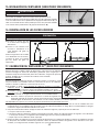
5. The minimum power pack distance above cooktop must not be less
than 24”. A maximum of 30” above cooktop is recommended for best
capture of cooking impurities.
6. Two installers are recommended because of the large size and weight
of this unit.
7. To reduce the risk of fire and to properly exhaust air, be sure to duct air
outside — Do not exhaust air into spaces within walls or ceiling or into
attics, crawl space or garage.
8. This product is equipped with a thermostat which may start blower
automatically. To reduce the risk of injury and to prevent power from
being switched on accidentally, switch power off at service panel and
lock or tag service panel.
9. Because of the high exhausting capacity of this unit, you should make
sure enough air is entering the house to replace exhausted air by
opening a window close to or in the kitchen.
10. To reduce the risk of fire and electrical shock, the Best models PK22
series should only be installed with their own built-in blowers, and the
Best models PKEX22 Series must only be installed with Best external
blower models EB6, EB9, EB12 or EB15; or Best in-line blowers
models ILB3, ILB6, ILB9, ILB11. Other blowers cannot be substituted.
11. PKEX22 models used with ILB3, ILB6 or EB6 blower, must be installed
over ranges rated 60,000 Btu/hr. maximum.
12. Please read specification label on product for further information and
requirements.
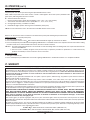
13. This power pack is equipped with a RF receiver (optional remote
control sold separately). Changes or modifications not expressly
approved by the party responsible for compliance could void the
user’s authority to operate this product. The remote control has been
tested and found to comply with the limits for a Class B digital device,
pursuant to part 15 of the FCC Rules and the Canadian ICES-003.
These limits are designed to provide reasonable protection against
harmful interference in a residential installation. The remote control
generates, uses and can radiate radio frequency energy and, if not
installed and used in accordance with the instructions, may cause
harmful interference to radio communications. However, there is no
guarantee that interference will not occur in a particular installation. If
this equipment does cause harmful interference to radio or television
reception, which can be determined by turning the equipment off and
on, the user is encouraged to try to correct the interference by one or
more of the following measures:
• Reorient or relocate the receiving antenna
• Increase the separation between the equipment and receiver
• Connect the equipment into an outlet on a circuit different from that
to which the receiver is connected
WARNING
!
CAUTION

3
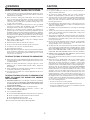
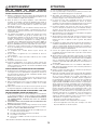
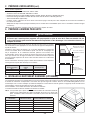
HL0192
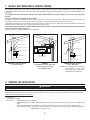
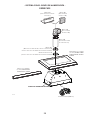
- PK22 POWER PACK SYSTEM -
MODEL 437
(H
IGH CAPACITY ROOF CAP)
M
ODEL 441
(10’’ R
OUND WALL CAP)
MODEL 418
(10” ROUND
ADJUSTABLE ELBOW)
MODEL 410
(10” ROUND DUCT
— 2 FT. SECTIONS)
AL3036, AL3042, AL3948,
AL3954, AL4554 OR AL4560
CUSTOM HOOD LINER (OPTIONAL)
MODEL 421
(10” ROUND VERTICAL IN-LINE DAMPER
SUPPLIED
WITH INTERNAL BLOWER POWER PAC K)
10” ROUND ADAPTER
(SUPPLIED WITH INTERNAL
BLOWER POWER PACK )
DUAL BLOWER (1200 CFM)
ALP36, ALP42, ALP48,
ALP54 OR ALP60
AMBIENT LIGHT PANEL (OPTIONAL)
PK22 POWER PACK

4
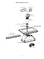
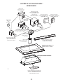
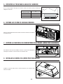
HL0193
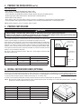
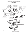
- PKEX22 POWER PACK SYSTEM -
MODEL 437
(H
IGH CAPACITY ROOF CAP)
M
ODEL 441
(10’’ ROUND
WALL CAP)
MODEL 418
(10” ROUND
ADJUSTABLE ELBOW)—
OPTIONAL
MODEL 410
(10” ROUND DUCT
— 2 FT. SECTIONS)
AL3036, AL3042, AL3948,
AL3954, AL4554
OR AL4560
CUSTOM HOOD LINER (OPTIONAL)
MODEL 643
(8” ROUND
WALL
CAP)
IN-LINE AND EXTERNAL BLOWER ROUGH-IN KIT
(INCLUDED WITH EB6, EB9, EB12, EB15,
ILB3, ILB6, ILB9 AND ILB11 BLOWERS.)
ALP36, ALP42, ALP48,
ALP54 OR ALP60
AMBIENT LIGHT PANEL (OPTIONAL)
PKEX22 POWER PACK
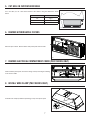
MODEL EB6 (600 CFM)
OR EB9 (900 CFM)
EXTERNAL BLOWER
MODEL EB12 (1200 CFM)
OR EB15 (1500 CFM)
EXTERNAL BLOWER
MODEL ILB3 (280 CFM)
IN-LINE BLOWER
(INCLUDES ONE 8” TO 10”
ROUND TRANSITION)
MODEL ILB6 (600 CFM)
IN-LINE BLOWER
(INCLUDES TWO 4½” X 18½”
TO 10’’ ROUND TRANSITIONS)
M
ODEL ILB9 (800 CFM)
OR ILB11 (1100 CFM)
IN-LINE BLOWER
(INCLUDES TWO 8” X 12” TO
10’’ ROUND TRANSITIONS)

5
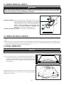
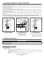
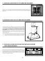
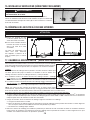
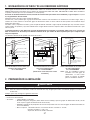
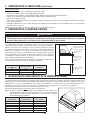
1. INSTALL DUCTWORK AND ELECTRICAL WIRING
For a PKEX22 series power pack, either an external blower or in-line blower must be used. The PKEX22 series power pack must be
installed with blower models ILB3, ILB6, ILB9, ILB11, EB6, EB9, EB12 or EB15 only. Other blowers cannot be substituted (blowers sold
separately.)
If installing external or in-line blower, refer to instructions packed with blower and follow steps 1 to 6, 11 to 16, 18 and up of this
manual.
Plan where and how the ductwork will be installed.
A straight, short duct run will allow the power pack to perform most efficiently. Long duct runs, elbows and transitions will reduce the
performance of the power pack. Use as few of them as possible. Larger ducting may be required for longer duct runs.
Install proper-sized ductwork, elbows and roof or wall cap for the type of blower you are installing. Connect metal ductwork to cap and work
back towards the hood location. Use 2” metal foil duct tape to seal the joints.
The minimum power pack distance above cooktop must not be less than 24’’. A maximum of 30” above cooktop is recommended
for best capture of cooking impurities.
Distances over 30” are at the installer and users discretion.
HH0189A
POWER PAC K
ROOF CAP
WALL
CAP
10” ROUND DUCT
10” ROUND ADAPTER
24” TO 30”
ABOVE COOKING SURFACE
10” ROUND ELBOW
10” VERTICAL DAMPER
IN-LINE BLOWER
10” ROUND DUCT
(EXCEPT ILB3, 8’’ ROUND DUCT)
HH0190A
24” TO 30” ABOVE
COOKING
SURFACE
ROOF CAP
WALL
CAP
POWER PACK
HH0191A
POWER PACK
EXTERNAL BLOWER
10” ROUND DUCT
24” TO 30”
ABOVE COOKING SURFACE
10” ROUND ELBOW
EXTERNAL
BLOWER
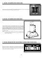
PK22 DUAL INTERNAL BLOWER
TYPICAL DUCTWORK
PKEX22
IN-LINE BLOWER TYPICAL DUCTWORK
(BLOWER LOCATION IS SHOWN
FOR REFERENCE ONLY)
PKEX22 EXTERNAL BLOWER
TYPICAL DUCTWORK
NOTE: For external blowers mounted in
close proximity to power pack,
sound level may be higher than
specified for internal blowers.
2. PREPARE THE INSTALLATION
WARNING
!
When performing installation, servicing or cleaning the unit, it is recommended to wear safety glasses and gloves.
NOTE: Before proceeding to the installation, check the contents of the box. If items are missing or damaged, contact the manufacturer.
Make sure that the following items are included:
- Power pack
- Installation instructions
- Accessories: • 2 Hybrid baffle filters with handles
• Shielded halogen bulbs (120 V, 50 W with GU10 base) (2 for 30” and 39” width power packs, 3 for 45” width power
pack)
• 10” round adapter and 10” round damper (included with PK22 power pack series only, not with PKEX22 series)
• Bag of parts including: 1 wire clamp, 2 wire connectors, 2 no. 8 x 3/8” screws, 6 no. 8-18 x 1¼” chrome plated screws.
If applicable, discard extra screws.

6
2. PREPARE THE INSTALLATION (CONT’D)
Parts sold separately:
- In-line blower assembly model ILB3, ILB6, ILB9 or ILB11.
- External blower assembly model EB6, EB9, EB12 or EB15.
- Custom hood liner model AL3036, AL3042, AL3948, AL3954, AL4554 or AL4560 (optional).
- Ambient light panel model ALP36, ALP42, ALP48, ALP54 or ALP60 (optional).
- ACR2 remote control (optional).
- Ducts, elbows, wall or roof caps. Refer to pages 3 and 4 for a complete list of venting options and model numbers.
- 10” round adapter with rough-in plate kit for PKEX22 series models (included with in-line or external blower kits).
NOTE: During installation, protect countertop and/or cooktop.
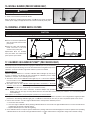
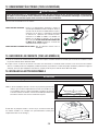
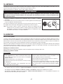
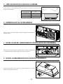
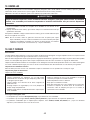
3. PREPARE CUSTOM HOOD
WARNING
!
• When building a custom hood, always follow all applicable construction codes and standards.
• Make sure the cabinet is capable of supporting its own weight and the weight of the power pack. Failure to do
so may cause personal injury or damage to countertop or cooktop.
The custom hood must be constructed to fit the size and shape of the power pack.
Proper structural support is required to accommodate the weight of the hood.
Start with the custom hood base, because its position will determine the height of the
power pack. We recommend the base of the custom hood should be 3/4-inch thick
plywood. If an optional custom hood liner will be installed, we recommend the sides
and front of the custom hood to be 3/4-inch thick, assuming standard cabinet width .
If the optional custom hood liner will not be installed, the custom hood side and front
thickness is at the installer’s discretion.
Run power cable to installation location. Stub out a 4-foot length of electrical cable
below the custom hood.
STANDARD 36” H.
COOKTOP
HH0192A
24” TO 30” ABOVE
COOKING SURFACE
PLYWOOD BASE
THICKNESS: 3/4”
4” FOR LINER
INSTALLATION
POWER PACK WIDTH WITH INTERNAL BLOWER WITH IN-LINE OR EXTERNAL BLOWER
30" 50 LB.-
39" 54 LB. 36 LB.
45" 57 LB. 39 LB.
4. INSTALL CUSTOM HOOD LINER (OPTIONAL)
The liners are especially designed to protect the exterior base of the custom hood. Refer to the table below to find the right liner model number
for your power pack and custom hood width. To view specifications, including depth for each liner model, visit www.BestRangeHoods.com
or contact Technical support (phone number listed on page 13, in warranty text).
To install, see instructions packed with custom hood liner. The liner must be installed before the power pack.
NOTE: On some liner models, the front liner piece may overlap the power pack front flange. If so, remove the front liner piece, assemble
power pack, and reassemble the front liner piece.
HA0099A
LINER MODEL POWER PACK MODEL CUSTOM HOOD NOMINAL WIDTH
AL3036 PK2230 36"
AL3042 PK2230 42"
AL3948 PK2239/PKEX2239 48"
AL3954 PK2239/PKEX2239 54"
AL4554 PK2245/PKEX2245 54"
AL4560 PK2245/PKEX2245 60"

7
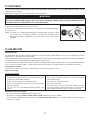
5. CUT HOLE IN CUSTOM HOOD BASE
A
HD0496A
14
7
⁄8"
If it is not done yet, cut a hole in the bottom of the cabinet, using the dimensions shown
below.
POWER PACK WIDTH A
30" 26
3
⁄16"
39" 34
15
⁄16"
45" 41
7
⁄8"
6. REMOVE HYBRID BAFFLE FILTERS
HD0499
Remove tape on filters. Remove filters from power pack and set aside.
7. REMOVE ELECTRICAL COMPARTMENT COVER (PK22 SERIES ONLY)
From inside the power pack, remove the wiring cover by removing its retaining
screw and set aside.
HD0502
SCREW
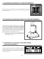
8. INSTALL WIRE CLAMP (PK22 SERIES ONLY)
HR0087
Install the wire clamp (included in parts bag) on top of the power pack.

8
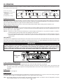
9. INSTALL 10" ADAPTER (PK22 SERIES ONLY)
Using 2 no. 8 x 3/8” screws from parts bag, assemble the adapter on the top of the power pack.
Seal all joints with metal foil duct tape to eliminate air leaks.
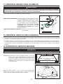
10. INSTALL 10" DAMPER (PK22 SERIES ONLY)
Install 10” damper (model 421, provided with PK22 series power packs)
inside the vertical ductwork that will be attached to the power pack. Do not
install in a horizontal ductwork or directly on top of the adapter or it will
not open and close properly. Remove shipping tape if present. Secure the
damper to the duct with 3 no. 8 sheet metal screws (not provided). Ensure
the damper opens and closes freely. Seal all joints with metal foil duct tape
to eliminate air leaks.
NOTE: To optimize airflow and reduce noise, position the damper at least
17” above the top of the power pack; or as far as the duct run will
allow (see figure at right).
HJ0070A
17” MIN.
11. INSTALL ROUGH-IN PLATE FOR EXTERNAL BLOWER (PKEX22 SERIES ONLY)
Refer to the instructions included with the selected blower/rough-in kit (sold
separately) for details on installing the rough-in plate. Install the rough-in
plate so that the wiring box is located on the right side when facing the hood,
as specified on the blower housing label.
HD0500
WIRING
COVER
LOCK NUTS
HJ0026
MOUNTING SCREW LOCATIONS

9
12. CONNECT WIRING (ALL MODELS)
WARNING
!
Risk of electric shock. Electrical wiring must be done by qualified personnel in accordance with all applicable
codes and standards. Before connecting wires, switch power off at service panel and lock service disconnecting
means to prevent power from being switched on accidentally.
Position the power pack below its custom hood.
HE0157
INTERNAL BLOWERS: Insert the house wiring cable through the wire clamp
previously installed in step 8. Tighten the wire clamp to
secure the cable. Connect cable into electrical compartment
using included wire connectors. Connect BLACK to BLACK,
WHITE to WHITE and GREEN or bare wire under green
ground screw. DO NOT FORGET TO CONNECT THE
GROUND. Reinstall electrical compartment cover.
IN-LINE OR EXTERNAL BLOWERS: See instructions included with blower.
13. CONNECT DUCTING (ALL MODELS)
A. When there is access to the top of the hood, connect ductwork and seal connections with metal foil duct tape after Step 14 Install power
pack.
B. When there is no access to the top of the hood, carefully pull down the metal duct through the custom hood base hole. Slide this duct
over the adapter (internal blower) or over the flange of the rough-in plate (in-line or external blower). Make sure the adapter/damper
assembly enters the ducting. Seal joint with metal foil duct tape.
14. INSTALL POWER PACK
CAUTION
Take care not to kink ducting when installing the power pack.
TIP: Two of the six no. 8-18 x 1¼” provided chrome plated screws can be
used to temporarely support the power pack during installation. Place
the power pack inside the custom hood and insert both side screws.
The power pack can now be secured to the custom hood without having
to hold it in place.
HD0497
SUPPORT SCREW LOCATIONS
HD0498
MOUNTING SCREW LOCATIONS
Using provided no. 8-18 x 1¼” chrome plated screws, secure the power pack
inside the custom hood. Install 1 screw at each corner. (See figure at right for
mounting screw locations.)

10
15. INSTALL BLOWER (PKEX22 SERIES ONLY)
WARNING
!
Do not plug the two cords together.
BA
HE0078
To install, see instructions packed with blower.
Once the blower is installed, plug the blower cord (B) into the female receptacle
and the power supply cord (A) onto the male connector inside the power pack.
16. REINSTALL HYBRID BAFFLE FILTERS
CAUTION
Remove protective plastic film covering hybrid baffle filters before installing them.
Insert one end of the hybrid baffle
filter into the back channel of the
power pack.
Raise the other end toward the
inside and insert in the front
channel of the power pack.
Replacement filters are available
from your dealer. See label inside
power pack for part number.
1
HD0501
2
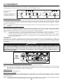
17. CALIBRATE IQ BLOWER SYSTEM™ (PK22 SERIES ONLY)
After the power pack is installed and wired, engage the calibration process (our Guaranteed
Performance System Technology to ensure full-rated airflow is being delivered). Prior to
calibration, ensure that all filters, light bulbs and duct system are installed.
CALIBRATION PROCESS
Hold the calibration button for 3 seconds; calibration button will light up and stay on
for up to 13 minutes. The blower will start and begin the calibration process. When
calibration is complete, one of two things will occur:
A. The blower turns off and calibration button light stays on = Successful calibration.
Press the button to turn off the LED. NOTE: The LED will also turn off if you select any
blower speed on the control.
B. The blower turns off and calibration button light blinks continuously = Too much
restriction in the ductwork is preventing the IQ Blower System™ from achieving the
rated airflow. The blower is automatically set to maximum intensity.
NOTE: Common items that cause restrictions: restricted damper flap (backdraft
damper, wall cap, roof cap), too many elbows, duct size less than 80% of hood outlet, poor transition, use of flex ducting and/or
crushed ducting.
Three options are available if your power pack system has too much restriction:
1. Accept airflow as is. Press the calibration button to accept airflow as is. The IQ Blower System™ is now configured to its highest possible
performance. The blinking calibration light goes out. NOTE: The LED will also turn off if you select any blower speed on the control.
2. Correct duct restriction, clear the original calibration data, and repeat the calibration process.
a. Correct the duct restriction.
b. Clear the original calibration data by holding calibration button for 10 seconds. The light will blink 3 times to confirm and the blower
configuration will go back to default settings.
c. Repeat calibration process from the beginning.
3. Clear calibration data to reset power pack to default factory settings and achieve standard high pressure blower performance by holding
calibration button for 10 seconds. The light will blink 3 times to confirm and the blower configuration will go back to default settings.
HC0066
CALIBRATION BUTTON
CALIBRATION LIGHT

11
18. LIGHT BULBS
This power pack requires shielded halogen lamps (120 V, 50 W, PAR16 with GU10 base, 2 for 30” and 39” width power packs, 3 for 45”
width power pack), included.
NOTE: Before using lamps, remove shipping tape on them (if present).
1. Install the lamps by placing the bulb leads into their grooves in the socket.
2. Gently push upwards and turn clockwise until secure.
To remove lamps, gently push upwards and turn counterclockwise to disengage bulb leads
from their grooves.
NOTE: If need be, use a rubber dishwashing glove to add grip when removing the bulb;
or use suction cup tool available from Best to ease removal of the bulbs. Contact
Best Customer Service at 1-800-558-1711 to order suction cup tool, part number
99526707.
WARNING
!
Do not touch lamps during or soon after operation. Burns may occur. In order to prevent the risk of personal injury,
only install shielded halogen lamps. Also, never install a cool beam, a dichroic lamp, a lamp not suitable for use in
recessed luminaires or identified for use in enclosed fixtures.
12
HO0090
19. USE AND CARE
Hybrid Baffle Filters
The hybrid baffle filters should be cleaned frequently. Use a warm detergent solution. Wash more often if your cooking style generates
greater grease — like frying foods or wok cooking.
Remove hybrid baffle filters by pushing them towards the back of power pack and rotating filters downward. Baffle filters are dishwasher
safe. Allow filters to dry completely before reinstalling them in the power pack.
Clean all-metal filters in the dishwasher using a non-phosphate detergent. Discoloration of the filter may occur if using phosphate detergent
or as a result of local water conditions — but this will not affect filter performance. This discoloration is not covered by the warranty.
Internal Blowers Cleaning
Remove filters in order to access blowers. Vacuum blowers to clean. Do not immerse in water.
Power Pack Cleaning
Stainless steel cleaning:
Avoid when choosing a detergent:
- Any cleaners that contain bleach will attack stainless steel.
- Any products containing: chloride, fluoride, iodide, bromide will deteriorate surfaces rapidly.
- Any combustible products used for cleaning such as acetone, alcohol, ether, benzol, etc., are highly explosive and should never be
used close to a range.
Do:
• Regularly wash with clean cloth or rag soaked with warm water
and mild soap or liquid dish detergent.
• Always clean in the direction of original polish lines.
• Always rinse well with clear water (2 or 3 times) after cleaning.
Wipe dry completely.
• You may also use a specialized household stainless steel
cleaner.
Don’t:
• Use any steel or stainless steel wool or any other scrapers to
remove stubborn dirt.
• Use any harsh or abrasive cleansers.
• Allow dirt to accumulate.
• Let plaster dust or any other construction residues reach the
power pack. During construction/renovation, cover the power
pack to make sure no dust sticks to stainless steel surface.

12
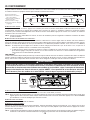
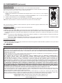
20. OPERATION
Always turn your blower on before you begin cooking to establish an airflow in the kitchen. Let the blower run for a few minutes to clear
the air after you turn off the range.
HC0016
SPEED 1 2 3 4 LIGHTING INTENSITY 1 2 3
BA C D E
A. BLOWER DELAY-OFF BUTTON:
When blower is on, press the delay-off button to activate the delay-off function. The corresponding speed indicator LED will start flashing to
indicate this function is activated. The fan will continue to operate for 10 minutes and will stop automatically. To cancel the delay-off function,
press the blower delay-off button once again; the blower will then work in normal mode.
NOTE: The blower speed can be increased—or decreased—during delay-off mode without starting another 10-minute cycle.
B. ON
BLOWER/SPEED CONTROL BUTTON:
Press this button to turn on the blower at the last selected speed. To change the blower speed, press the button again until the desired
speed is obtained. Press and hold this button for 2 seconds to decrease the speed level down by one increment. Possible decreases are
then: 4 to 3; 3 to 2; 2 to 1 and 1 to OFF.
NOTES: 1. Each time you press the speed control button, the speed changes by increments of 1 (e.g.: speed 1 to speed 2, to speed 3,
and then speed 4). From the fourth speed, the speed goes down to level 1.
2. The last speed used is kept in memory so that when the unit is turned on, it will return to the last setting except the fourth, the
next time the blower will be turned on, it will return to speed 3. The memorized speed level is also synced with the optional
remote control.
HEAT SENTRY™
The power pack is equipped with a protective device that activates when excessive heat is detected inside the power pack. This device
takes control of the blower and deactivates speed 4 for a 10-minute period and sets it on speed 3. During the Heat Sentry activation, only
speed 3 can be used; the speed 4 button will flash while the speed 3 button will light up.
C. OFF
BLOWER/FILTER MAINTENANCE BUTTON:
Press this button to turn off the blower. Pressing this button also cancels the delay-off function (if activated).
NOTE: After 25 hours of operation, the 4 blower speed lights will flash 30 seconds to indicate the filters need to be cleaned in order
to maintain efficient power pack operation. Pressing the OFF button will reset the code to indicate that maintenance has been
completed.
D. OFF
LIGHTING:
Press this button to turn lights off.
E. ON
LIGHT BUTTON:
Press this button to turn on the halogen lamps. The light intensity changes by increments of 1 (e.g.: Press once for low setting, once again
for medium, again for high). From the higher setting, press once to go back to the lower setting.
NOTE: The last light setting used is kept in memory. The next time the halogen lamps are turned on, the last setting will be used. The
memorized light setting is also synced with the optional remote control.
WARNING
!
The HEAT SENTRY can start the blower during a range top fire or other excessive heat situations even if the power
pack is turned off. In this case, it is impossible to turn the blower OFF with blower button. If you must stop the
blower on PK22 series models: set the main power switch located behind the baffle filters in OFF position, if it is
possible to do safely (see illustration below). For PKEX22 series models: do it from the main electrical panel.
A) Blower delay-off button
B) ON blower/Speed control button
C) OFF blower/
Filter maintenance button
D) OFF lighting
E) ON light button (3 settings)
HD0517
MAIN
POWER
SWITCH
PK22 SERIES
ONLY

13
20. OPERATION (CONT’D)
21. WARRANTY
ONE-YEAR LIMITED WARRANTY FOR BEST PRODUCTS
Broan-NuTone LLC (Broan-NuTone) warrants to the original consumer purchaser of its products that such products will be free from
defects in materials or workmanship for a period of one year from the date of original purchase. THERE ARE NO OTHER WARRANTIES,
EXPRESS OR IMPLIED, INCLUDING, BUT NOT LIMITED TO, IMPLIED WARRANTIES OF MERCHANTABILITY OR FITNESS FOR
A PARTICULAR PURPOSE.
During this one-year period, Broan-NuTone will, at its option, repair or replace, without charge, any product or part which is found to be
defective under normal use and service.
This warranty does not extend to fluorescent lamp starters, tubes and bulbs, fuses, filters, ducts, roof caps, wall caps and other
accessories for ducting. This warranty does not cover (a) normal maintenance and service or (b) any products or parts which have been
subject to misuse, negligence, accident, improper maintenance or repair (other than by Broan-NuTone), faulty installation or installation
contrary to recommended installation instructions.
The duration of any implied warranty is limited to the one-year period as specified for the express warranty. Some states or provinces do
not allow limitation on how long an implied warranty lasts, so the above limitation may not apply to you.
BROAN-NUTONE’S OBLIGATION TO REPAIR OR REPLACE, AT BROAN-nutone’S OPTION, SHALL BE THE PURCHASER’S
SOLE AND EXCLUSIVE REMEDY UNDER THIS WARRANTY. BROAN-nutone SHALL NOT BE LIABLE FOR INCIDENTAL,
CONSEQUENTIAL OR SPECIAL DAMAGES ARISING OUT OF OR IN CONNECTION WITH PRODUCT USE OR PERFORMANCE.
Some states or provinces do not allow the exclusion or limitation of incidental or consequential damages, so the above
limitation or exclusion may not apply to you.
This warranty gives you specific legal rights, and you ma y also have other rights, which vary from state to state or province to another.
Any modification performed on this product without the authorization of Broan-NuTone will void this warranty. This warranty supersedes
all prior warranties.
To qualify for warranty service, you must (a) notify Broan-NuTone at the address or telephone number stated below, (b) give the model
number and part identification and (c) describe the nature of any defect in the product or part. At the time of requesting warranty service,
you must present evidence of the original purchase date.
In USA - Best
®
, 926 W. State Street, Hartford, WI 53027 (1-800-558-1711)
In Canada - Best
®
, 550 Lemire Blvd., Drummondville, QC, Canada (1-866-737-7770)
www.bestrangehoods.com
OPTIONAL REMOTE CONTROL:
The power pack can also be operated using the optional ACR2 remote control.
When a button is pressed on the remote control, it sends a coded signal to the receiver (factory installed on the
power pack), indicating which function to activate.
¤ : Activates/deactivates delay-off.
- : Decreases blower motor speed until turned OFF (4 to 3, 3 to 2, 2 to 1 and 1 to OFF).
+ : Turns blower motor ON and increases speed (OFF to 1, 1 to 2, 2 to 3, 3 to 4).
: Changes light intensity (1-2-3-OFF-1-2-3-OFF).
1 : LED indicator (lights up blue when signal is transmitted to power pack).
NOTE: For more information, refer to the instructions included with the remote control.
Before it can be used, the remote control has to be linked to the power pack following the procedure below.
L
INKING PROCEDURE (to a specific power pack):
1- Turn lights and blower off.
2- Press and hold the remote control
¤
button until the blue LED indicator lights up and release the button.
3- Press and hold power pack button A until the lighting LED indicators 1 and 3 blink 3 times. This completes the link of the remote. Linking
procedure needs to be confirmed within 30 seconds, otherwise it will be cancelled.
NOTES: 1. Pressing power pack button A for 3 seconds will not enter the linking mode. The linking mode can only be activated from the
remote control
¤
button.
2. Since the code is randomly assigned, it may be necessary to repeat the procedure in apartments or condos where many
products controlled by a remote control are close to each other.
U
NLINKING PROCEDURE:
1- Turn lights and blower off.
2- Press and hold power pack button E for 10 seconds. Lighting LED indicator 2 will then blink 3 times as a completion feedback.
HC0070
-
+
¤
1

14
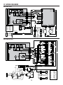
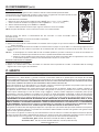
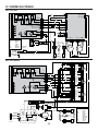
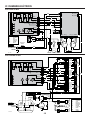
22. WIRING DIAGRAMS
COLOR CODE
BLK BLACK
BLU BLUE
RED RED
ORG ORANGE
WHT WHITE
YEL YELLOW
LINE
NEUTRAL
GROUND
120 VAC
K1 K2 K3 K4
MOTOR
HIGH
MED HIGH
MED LOW
LOW
LAMP
LOW VAC
R
EF
J7
J1
5
4
3
2
1
3
2
1
Q1
~
~
-+
~
~
-
+
BLK
WHT
YEL
WHT
RED
BLK
RED
WHT
BLK
WHT
T1
MAIN SWITCH
LAMP LAMP LAMP
M
M
BLK BLK
NEUTRAL
SPEED 1
S
PEED 2
SPEED 3
S
PEED 4
C
ALIBRATION BUTTON
RELAY INTERFACEPOWER CALIBRATION
MT_THM1
MT_T
HM2
BLDC1 BLDC2H
ALL_1 HALL_2
WHT
WHT
3
2
1
3
2
1
HE0156A
5
4
3
2
1
E
L
N
WHT
ORG
BLK
BLU
WHT
J6
5
4
3
2
1
RF RECEIVER
Best PK22 series
HE0155A
FUSE 8 A
K1 K2 K3 K4
Q1
~
~
-+
~
~
-
+
J7
J1
5
4
3
2
1
3
2
1
J6
5
4
3
2
1
WHT
WHT
BLK
BLK
BLK
WHT
GRN
M
WHT
BLK
BLK
WHT
GRN
WHT
BLK
T1
T2
T3
BLK
BLK
BLK
BLK
BLK
BLK
ORG
ORG
ORG
ORG
WHT
WHT
WHT
WHT
WHT
WHT
WHT
WHT
WHT
BLU
BLU
BLU
BLU
YEL
RED
BLK 120
ORG 120
BLU 88
PPL 60
PNK 45
YEL 10
WHT 0
WHT 0
9
8
7
6
5
4
3
2
1
9
8
7
6
5
4
3
2
1
9
8
7
6
5
4
3
2
1
9
8
7
6
5
4
3
2
1
9
8
7
6
5
4
3
2
1
9
8
7
6
5
4
3
2
1
BLK
YEL
ROUGH-IN PLATE
RF RECEIVER
LINE
NEUTRAL
GROUND
120 VAC
MOTOR
HIGH
MED HIGH
MED LOW
LOW
LAMP
LOW VAC
R
EF
LAMP LAMP LAMP
COLOR CODE
BLK BLACK
BLU BLUE
BRN BROWN
GRN GREEN
ORG ORANGE
PNK PINK
PPL PURPLE
RED RED
WHT WHITE
YEL YELLOW
BLK 120
ORG 120
BLU 88
PPL 60
PNK 45
YEL 10
WHT 0
WHT 0
BLK 120
ORG 120
BLU 88
PPL 60
PNK 45
YEL 10
WHT 0
WHT 0
Best PKEX22 series

15
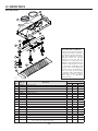
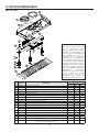
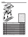
23. SERVICE PARTS
Best PK22 Series
HL0199
5
12
11
7
8
9
10
16
4
15
14
13
2
1
6
3
REPLACEMENT PARTS AND REPAIRS
In order to ensure your unit remains in
good working condition, you must use
Broan-NuTone genuine replacement
parts only. Broan-NuTone genuine
replacement parts are specially
designed for each unit and are
manufactured to comply with all the
applicable certification standards and
maintain a high standard of safety.
Any third party replacement part
used may cause serious damage and
drastically reduce the performance
level of your unit, which will result
in premature failing. Broan-NuTone
recommends to contact a certified
service depot for all replacement
parts and repairs.
KEY
NO.
PART NO.DESCRIPTION
QTY. (POWER PACK WIDTH)
30" 39" 45"
1 SV08541 10” ROUND ADAPTER 111
2 SV08542 10” ROUND DAMPER 111
3 S97018985 BLDC BLOWER, 600 CFM 2 2 2
4 SV20818 E
LECTRONIC DRIVE FOR DUAL BLDC BLOWER 111
5 SV20817 C
ALIBRATION BUTTON 111
6 SV08548 B
LACK ROCKER SWITCH 111
7 SV05917 SOCKET GU10 2 2 3
8 SV09435 SOCKET HOLDER GU10 2 2 3
9 SV09434 LIGHT TRIM STAINLESS STEEL 223
10 SV05921 HALOGEN BULB 120 V, 50 W, PAR16 WITH GU10 BASE 223
11 SV61044 FILTER FILLER 002
12
SV61045 BAFFLE FILTER WITH MICROMESH + HANDLE 12” X 10” 200
SV61046 BAFFLE FILTER WITH MICROMESH + HANDLE 17” X 10” 022
13 SV20816 REMOTE CONTROL PCB 1 1 1
14 SV20814 CONTROL INTERFACE PCB FOR INTERNAL BLOWER 111
15 SV09022 T
RANSFORMER 120 VAC, 9 VOLTS DC 1 1 1
16 SV05869 BEST LOGO 111
* SV20827 INSTALLATION INSTRUCTIONS 111
* SV20830
PARTS BAG: 1 WIRE CLAMP, 2 WIRE CONNECTORS, 2 NO. 8 X 3/8” SCREWS,
6 NO. 8-18 X 1¼” CHROME PLATED SCREWS.
111
* NOT SHOWN.

16
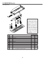
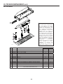
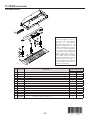
23. SERVICE PARTS (CONT’D)
Best PKEX22 Series
HL0200
3
4
5
6
1
9
7
8
10
11
2
12
REPLACEMENT PARTS AND REPAIRS
In order to ensure your unit remains in
good working condition, you must use
Broan-NuTone genuine replacement
parts only. Broan-NuTone genuine
replacement parts are specially
designed for each unit and are
manufactured to comply with all the
applicable certification standards and
maintain a high standard of safety.
Any third party replacement part
used may cause serious damage and
drastically reduce the performance
level of your unit, which will result
in premature failing. Broan-NuTone
recommends to contact a certified
service depot for all replacement
parts and repairs.
KEY
NO.
PART NO.DESCRIPTION
QTY. (POWER PACK WIDTH)
39" 45"
1 SV61049 AUTOTRANSFORMER AND FUSE KIT (INCLUDING METAL SUPPORT)11
2 SV20816 PCB FOR REMOTE CONTROL 11
3 SV05917 SOCKET GU10 2 3
4 SV09435 SOCKET HOLDER GU10 2 3
5 SV09434 LIGHT TRIM STAINLESS STEEL 23
6 SV05921 H
ALOGEN BULB 120 V, 50 W, PAR16 WITH GU10 BASE 23
7 SV61044 FILTER FILLER 02
8 SV61046 BAFFLE FILTER WITH MICROMESH + HANDLE 17” X 10” 2 2
9 SV13924 MALE POWER CONNECTOR 11
10 SV13923 FEMALE POWER CONNECTOR 11
11 SV20815 CONTROL INTERFACE PCB FOR EXTERNAL BLOWER 11
12 SV05869 BEST LOGO 11
* SV20827 I
NSTALLATION INSTRUCTIONS 11
* SV20830
P
ARTS BAG: 1 WIRE CLAMP, 2 WIRE CONNECTORS, 2 NO. 8 X 3/8” SCREWS,
6 NO. 8-18 X 1¼” CHROME PLATED SCREWS.
11
* NOT SHOWN.

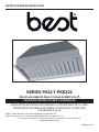
SÉRIES PK22 ET PKEX22
GUIDE D’INSTALLATION
HB0123
CONÇUES POUR USAGE DOMESTIQUE SEULEMENT
INSTALLATEUR : LAISSER CE GUIDE AU PROPRIÉTAIRE.
PROPRIÉTAIRE : DIRECTIVES D’UTILISATION ET D’ENTRETIEN
EN PAGES 27 À 29.
LIRE ET CONSERVER CES DIRECTIVES
BEST; Hartford, Wisconsin www.BestRangeHoods.com 800 558-1711
BEST; Drummondville, QC, Canada www.BestRangeHoods.com 866 737-7770
Pour enregistrer votre produit en ligne ou pour obtenir plus d’information,
consultez notre site www.BestRangeHoods.com
SV20827 rév. 07
! !

18
AFIN DE RÉDUIRE LES RISQUES D’INCENDIE,
D’ÉLECTROCUTION OU DE BLESSURES CORPORELLES,
SUIVEZ LES DIRECTIVES SUIVANTES :
1. N’utilisez cet appareil que de la façon prévue par le manufacturier. Si
vous avez des questions, contactez le manufacturier à l’adresse ou au
numéro de téléphone indiqués dans la garantie.
2. Avant de réparer ou de nettoyer l’appareil, couper l’alimentation
électrique en verrouillant le panneau de distribution afin d’éviter sa
remise en marche accidentelle. Si le panneau de distribution ne peut
être verrouillé, y fixer un avertissement en évidence, telle qu’une
étiquette de couleur vive.
3. Les travaux d’installation et de raccordement électrique doivent être
effectués par une personne qualifiée, conformément aux codes et
aux standards de construction, incluant ceux concernant la protection
contre les incendies.
4. Une quantité d’air adéquate est requise afin d’assurer une bonne
combustion et l’évacuation des gaz par la cheminée dans le cas
des équipements alimentés au gaz afin de prévenir les retours de
cheminée. Conformez-vous aux instructions et aux standards de
sécurité des manufacturiers d’équipement de chauffage, tel qu’ils
sont publiés par la National Fire Protection Association (NFPA) et
l’American Society for Heating, Refrigeration and Air Conditioning
Engineers (ASHRAE) ainsi que les responsables des codes locaux.
5. Lorsque vous coupez ou perforez un mur ou un plafond, prenez garde
de ne pas endommager les fils électriques ou autre installation qui
pourraient y être dissimulés.
6. Les ventilateurs avec conduits doivent toujours évacuer l’air
à l’extérieur.
7. Ne pas utiliser cet appareil avec une commande de vitesse à
semi-conducteur.
8. Afin de réduire les risques d’incendie, n’utilisez que des conduits
de métal.
9. Cet appareil doit être mis à la terre.
10. Lorsqu’une réglementation est en vigueur et qu’elle comporte des
exigences d’installation et/ou de certification plus restrictives, lesdites
exigences prévalent sur celles de ce document et l’installateur entend
s’y conformer à ses frais.
AFIN DE RÉDUIRE LES RISQUES DE FEU DE CUISINIÈRE :
a) Ne jamais laisser les appareils de cuisson sans surveillance lorsqu’ils
sont réglés à feu vif. Les débordements engendrent de la fumée et
des déversements graisseux pouvant s’enflammer. Chauffez l’huile
lentement, à feu doux ou moyen.
b) Mettez toujours la hotte en marche lorsque vous cuisinez à feu vif ou
que vous cuisinez des mets flambés (par ex. : crêpes Suzette, cerises
jubilé, steaks au poivre flambés).
c) Nettoyez régulièrement la (les) roue(s) du ventilateur. Ne laissez pas
la graisse s’accumuler sur le ventilateur, les filtres ou les conduits
d’évacuation.
d) Utilisez le bon format de casserole. Servez-vous toujours de casseroles
et d’ustensiles appropriés à la dimension de la surface chauffante.
AFIN D’ÉVITER TOUT RISQUE DE BLESSURES LORS D’UN
FEU DE CUISINIÈRE, SUIVEZ CES DIRECTIVES* :
1. Étouffez les flammes avec un couvercle hermétique, une tôle à biscuits
ou un plateau métallique et ensuite, éteindre le brûleur. PRENEZ
SOIN D’ÉVITER les brûlures. SI LES FLAMMES NE S’ÉTEIGNENT
PAS IMMÉDIATEMENT, ÉVACUEZ LES LIEUX ET APPELEZ
LES POMPIERS.
2. NE PRENEZ JAMAIS UNE CASSEROLE EN FLAMMES DANS VOS
MAINS. Vous pourriez vous brûler.
3. N’UTILISEZ PAS D’EAU, incluant un linge à vaisselle ou une serviette
mouillée, cela pourrait occasionner une violente explosion de vapeur.
4. N’utilisez un extincteur QUE DANS LE CAS OÙ :
A. Vous savez qu’il s’agit d’un extincteur de classe ABC et que vous
en connaissez le fonctionnement.
B. L’incendie est petit et limité à l’endroit où il a débuté.
C. Les pompiers ont été avisés.
D. Vous pouvez combattre l’incendie en ayant accès à une sortie
de secours.
*Tirées du Kitchen Fire Safety Tips publié par la NFPA.
1. Pour une utilisation à l’intérieur seulement.
2. Pour usage domestique seulement. Ne pas utiliser pour évacuer des
vapeurs ou des matières dangereuses ou explosives.
3. Afin d’éviter tout dommage au moteur et de débalancer ou de
rendre bruyante la roue du moteur, garder votre appareil à l’abri des
poussières de gypse et de construction/rénovation, etc.
4. Le moteur de votre hotte encastrable possède une protection
thermique qui éteindra automatiquement le moteur s’il devient
surchauffé. Le moteur redémarrera automatiquement une fois refroidi.
Si le moteur continue à arrêter et à redémarrer, faites-le vérifier.
5. La distance minimale entre le bas de votre hotte et la surface de
cuisson ne doit pas être inférieure à 24 po. Un maximum de 30 po
au-dessus de la surface de cuisson est recommandé pour une
meilleure évacuation des odeurs de cuisson.
6. Deux installateurs sont recommandés lors de l’installation vu la grande
dimension et le poids de cet appareil.
7. Afin de réduire les risques d’incendie, assurez-vous d’évacuer l’air à
l’extérieur. Ne pas évacuer l’air dans des espaces restreints comme
l’intérieur des murs ou plafond ou dans le grenier, faux plafond
ou garage.
8. Cet appareil est équipé d’un thermostat pouvant faire démarrer le
ventilateur automatiquement. Afin de réduire le risque de blessure,
couper le courant à partir du panneau électrique et le verrouiller ou
apposer un avertissement sur le panneau afin de prévenir que la hotte
ne soit mise en marche accidentellement.
9. À cause de la grande capacité d’évacuation de cet appareil, il est
recommandé d’ouvrir une fenêtre dans ou près de la cuisine afin de
remplacer l’air évacué.
10. Afin de réduire les risques d’incendie et d’électrocution, les modèles
Best de la série PK22 doivent être installés uniquement avec leurs
ventilateurs internes intégrés et les modèles Best de la série PKEX22
avec les ventilateurs externes EB6, EB9, EB12 ou EB15 ou un
ventilateur en ligne ILB3, ILB6, ILB9, ILB11. Aucun autre ventilateur ne
doit être utilisé.
11. Les modèles PKEX22 utilisés avec les ventilateurs ILB3, ILB6 ou
EB6, doivent être installés au-dessus d’une cuisinière produisant un
maximum de 60 000 Btu/h.
12. Veuillez consulter l’autocollant apposé à l’intérieur du produit pour
plus d’information ou autres exigences.
13. Cette hotte encastrable est munie d’un récepteur radio (télécommande
optionnelle vendue séparément). Tous changements ou modifications
qui ne sont pas approuvés par la partie responsable de la
conformité pourraient annuler la possibilité d’opérer l’équipement.
La télécommande a été testée et est en accord avec les limites de
la Classe B appareil numérique et est conforme au chapitre 15 des
règlements FCC et ICES-003 canadien. Ces limites sont développées
afin de fournir une protection raisonnable contre des interférences
dommagables dans une installation résidentielle. La télécommande
génère, utilise et peut émettre des flux de fréquences radio qui
peuvent causer des interférences aux communications radio, si elle
n’est pas installée selon les instructions. Cependant, il n’y a aucune
garantie que ces dites interférences ne se produiront pas dans une
installation particulière. Si cet équipement cause des interférences
à un récepteur radio ou un téléviseur, cela peut être confirmé en
éteignant et rallumant l’appareil, l’usager est encouragé à corriger
cette situation en essayant les solutions suivantes :
• Réorienter ou relocaliser l’antenne réceptrice
• Augmenter la distance entre l’équipement et le récepteur
• Connecter l’équipement à une autre prise électrique ou un autre
disjoncteur différent de celui du récepteur
AVERTISSEMENT
!
ATTENTION

19
HL0192
- SYSTÈME DE HOTTE ENCASTRABLE -
SÉRIE PK22
MODÈLE 437
(CAPUCHON DE TOIT
À HAUT RENDEMENT)
M
ODÈLE 441
(CAPUCHON MURAL
10
PO ROND)
MODÈLE 418
(COUDE AJUSTABLE
DE 10 PO ROND)
MODÈLE 410
(CONDUIT DE 10 PO ROND
— SECTIONS DE 2 PI)
REVÊTEMENT D’ARMOIRE (OPTIONNEL)
AL3036, AL3042, AL3948,
AL3954, AL4554 OU AL4560
MODÈLE 421
(VOLET VERTICAL EN LIGNE DE 10 PO ROND
FOURNI
AVEC LA HOTTE ENCASTRABLE À VENTILATEUR INTERNE)
A
DAPTATEUR DE 10 PO ROND
(FOURNI AVEC LA HOTTE ENCASTRABLE À VENTILATEUR INTERNE)
V
ENTILATEUR INTERNE (1200 PI/MIN)
PANNEAU D’ÉCLAIRAGE D’AMBIANCE
(OPTIONNEL) ALP36, ALP42,
ALP48, ALP54 OU ALP60
HOTTE ENCASTRABLE PK22

20
HL0193
MODÈLE 437
(CAPUCHON DE TOIT
À HAUT RENDEMENT)
M
ODÈLE 441
(CAPUCHON MURAL
10 PO ROND)
MODÈLE 418
(COUDE AJUSTABLE
DE 10 PO ROND) —
OPTIONNEL
MODÈLE 410
(CONDUIT DE 10 PO ROND
— SECTIONS DE 2 PI)
R
EVÊTEMENT D’ARMOIRE (OPTIONNEL)
AL3036, AL3042, AL3948,
AL3954, AL4554 OU AL4560
MODÈLE 643
(CAPUCHON
MURAL
8 PO ROND)
PLAQUE VENTILATEUR POUR VENTILATEURS
EXTERNES OU EN LIGNE (INCLUSE AVEC LES
VENTILATEURS EB6, EB9, EB12, EB15,
ILB3, ILB6, ILB9 ET ILB11).
P
ANNEAU D’ÉCLAIRAGE D’AMBIANCE
(OPTIONNEL) ALP36, ALP42,
ALP48, ALP54 OU ALP60
HOTTE ENCASTRABLE PKEX22
VENTILATEUR EXTERNE
MODÈLE EB6 (600 PI/MIN)
OU EB9 (900 PI/MIN)
VENTILATEUR EXTERNE
MODÈLE EB12 (1200 PI/MIN)
OU EB15 (1500 PI/MIN)
V
ENTILATEUR EN LIGNE 10 PO
MODÈLE ILB3 (280 PI/MIN)
(INCLUANT UNE TRANSITION
RONDE
DE 8 PO À 10 PO)
V
ENTILATEUR EN LIGNE
MODÈLE ILB6 (600 PI/MIN)
(INCLUANT DEUX TRANSITIONS RONDES
DE 4½ PO X 18½ PO À 10 PO)
V
ENTILATEUR EN LIGNE
MODÈLE ILB9 (800 PI/MIN)
OU ILB11 (1100 PI/MIN)
(INCLUANT DEUX
TRANSITIONS RONDES DE
8 PO X 12 PO À 10 PO)
- SYSTÈME DE HOTTE ENCASTRABLE -
SÉRIE PKEX22
La page est en cours de chargement...
La page est en cours de chargement...
La page est en cours de chargement...
La page est en cours de chargement...
La page est en cours de chargement...
La page est en cours de chargement...
La page est en cours de chargement...
La page est en cours de chargement...
La page est en cours de chargement...
La page est en cours de chargement...
La page est en cours de chargement...
La page est en cours de chargement...
La page est en cours de chargement...
La page est en cours de chargement...
La page est en cours de chargement...
La page est en cours de chargement...
La page est en cours de chargement...
La page est en cours de chargement...
La page est en cours de chargement...
La page est en cours de chargement...
La page est en cours de chargement...
La page est en cours de chargement...
La page est en cours de chargement...
La page est en cours de chargement...
La page est en cours de chargement...
La page est en cours de chargement...
La page est en cours de chargement...
La page est en cours de chargement...
-
 1
1
-
 2
2
-
 3
3
-
 4
4
-
 5
5
-
 6
6
-
 7
7
-
 8
8
-
 9
9
-
 10
10
-
 11
11
-
 12
12
-
 13
13
-
 14
14
-
 15
15
-
 16
16
-
 17
17
-
 18
18
-
 19
19
-
 20
20
-
 21
21
-
 22
22
-
 23
23
-
 24
24
-
 25
25
-
 26
26
-
 27
27
-
 28
28
-
 29
29
-
 30
30
-
 31
31
-
 32
32
-
 33
33
-
 34
34
-
 35
35
-
 36
36
-
 37
37
-
 38
38
-
 39
39
-
 40
40
-
 41
41
-
 42
42
-
 43
43
-
 44
44
-
 45
45
-
 46
46
-
 47
47
-
 48
48


Best PK221 Guide d'installation
- Catégorie
- Hottes
- Taper
- Guide d'installation
dans d''autres langues
- English: Best PK221 Installation guide
- español: Best PK221 Guía de instalación