MTD TB55B Le manuel du propriétaire
- Catégorie
- Coupe-herbe
- Taper
- Le manuel du propriétaire

12 Volt Battery
Trimmer
Model TB55B
IMPORTANT: READ SAFETY RULES AND INSTRUCTIONS CAREFULLY
P/N 769-00532 (12/02)
PRINTED IN USA
Operator’s Manual

2
TABLE OF CONTENTS
Content Page
Calling Customer Support . . . . . . . . . . . . . . . . . . . . . . . . . . . . . . . . . . . . . . . . . . . . . . . . . . . . 2
Rules for Safe Operation . . . . . . . . . . . . . . . . . . . . . . . . . . . . . . . . . . . . . . . . . . . . . . . . . . . . . 3
Know Your Unit . . . . . . . . . . . . . . . . . . . . . . . . . . . . . . . . . . . . . . . . . . . . . . . . . . . . . . . . . . . . 6
Assembly Instructions . . . . . . . . . . . . . . . . . . . . . . . . . . . . . . . . . . . . . . . . . . . . . . . . . . . . . . . 7
Operating Instructions . . . . . . . . . . . . . . . . . . . . . . . . . . . . . . . . . . . . . . . . . . . . . . . . . . . . . . . 8
Maintenance and Repair Instructions . . . . . . . . . . . . . . . . . . . . . . . . . . . . . . . . . . . . . . . . . . 11
Cleaning and Storage. . . . . . . . . . . . . . . . . . . . . . . . . . . . . . . . . . . . . . . . . . . . . . . . . . . . . . . 14
Accessories and Replacement Parts. . . . . . . . . . . . . . . . . . . . . . . . . . . . . . . . . . . . . . . . . . . 14
Troubleshooting Chart . . . . . . . . . . . . . . . . . . . . . . . . . . . . . . . . . . . . . . . . . . . . . . . . . . . . . . 15
Specifications. . . . . . . . . . . . . . . . . . . . . . . . . . . . . . . . . . . . . . . . . . . . . . . . . . . . . . . . . . . . . 15
Warranty Information . . . . . . . . . . . . . . . . . . . . . . . . . . . . . . . . . . . . . . . . . . . . . . . . . . . . . . . 16
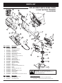
Parts List. . . . . . . . . . . . . . . . . . . . . . . . . . . . . . . . . . . . . . . . . . . . . . . . . . . . Inside Back Cover
This operator’s manual is an important part of your new trimmer. It will help you assemble, prepare and maintain the unit
for best performance. Please read and understand what it says.
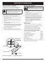
Before you start assembling your new equipment, please locate the model plate on the equipment and copy the
information from it in the space provided below. This information is very important if you need help from our Customer
Support Department or an authorized dealer.
• You can locate the model number on the unit. A sample model plate is explained below. For future reference,
please copy the model number and the serial number of the equipment in the space below.
If you have difficulty assembling this product or have any questions regarding the controls, operation or maintenance of
this unit, please call the Customer Support Department.
Call 1-800-520-5520 to reach a Customer Support representative. Please have your unit’s model number
and serial number ready when you call. See previous section to locate this information. You will be asked to
enter the serial number in order to process your call.
FINDING MODEL NUMBER
CALLING CUSTOMER SUPPORT
For more details about your unit, visit our website at www.troybilt.com
Copy the model and parent
part number here:
Copy the serial number here:
S/N :
ITEM :
MODEL :

3
READ ALL INSTRUCTIONS
BEFORE OPERATING
• Read the instructions carefully. Be familiar with the
controls and proper use of the unit.
• Do not operate this unit when tired, ill or under the
influence of alcohol, drugs or medication.
• Children and teens under the age of 15 must not use
the unit, except for teens guided by an adult.
• Inspect the unit before use. Replace damaged parts.
Check for battery leaks. Make sure all fasteners are in
place and secure. Replace cutting attachment parts
that are cracked, chipped or damaged in any way.
Make sure the cutting attachment is properly installed
and securely fastened. Be sure the cutting attachment
shield is properly attached, and positioned as
recommended. Failure to do so can result in personal
injury to the operator and bystanders, as well as
damage to the unit.
• Avoid dangerous environments. Never operate your
unit in damp or wet conditions. Moisture is a shock
hazard.
• Do not use the unit in the rain.
• Do not handle the unit with wet hands.
• Use only 0.080 inch (
2.03 mm) diameter Genuine
Factory Parts™ replacement line. Never use metal-
reinforced line, wire or rope. These can break off and
become dangerous projectiles.
• Be aware of the risk of injury to the head, hands and feet.
• Clear the area to be cut before each use. Remove all
objects such as rocks, broken glass, nails, wire or
string. They can be thrown or become entangled in the
cutting attachment. Clear the area of children,
bystanders, and pets. At a minimum, keep all children,
bystanders and pets outside a 50-foot (15 m.) radius;
there still may be a risk to bystanders from thrown
objects. Bystanders should be encouraged to wear
eye protection. If you are approached, stop the motor
and cutting attachment immediately.
• This unit was not designed to be used as a
brushcutter. Do not attach or operate this unit with any
type of brushcutting blade or brushcutting attachment.
SAFETY WARNINGS FOR BATTERY TRIMMERS
• Battery tools do not have to be plugged into an
electrical outlet; therefore, they are always in operating
condition. Be aware of possible hazards even when
the tool is idle. Take care when performing
maintenance or service.
• Remove or disconnect the battery before servicing,
cleaning or removing material from the unit.
• Only use the charging station provided with your unit.
Do not substitute any other charging equipment. Use
of any other means of charging could cause the
batteries to explode, resulting in possible serious
personal injury.
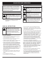
DANGER: Failure to obey a safety warning
will result in serious injury to yourself or to
others. Always follow the safety precautions
to reduce the risk of fire, electric shock and
personal injury.
WARNING: Failure to obey a safety warning
can result in injury to yourself and others.
Always follow the safety precautions to
reduce the risk of fire, electric shock and
personal injury.
CAUTION: Failure to obey a safety warning
may result in property damage or personal
injury to yourself or to others. Always follow
the safety precautions to reduce the risk of
fire, electric shock and personal injury.
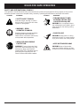
SAFETY ALERT SYMBOL: Indicates danger,
warning or caution. Attention is required in
order to avoid serious personal injury. May be
used in conjunction with other symbols or
pictographs.
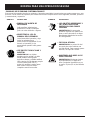
SYMBOL MEANING
The purpose of safety symbols is to attract your
attention to possible dangers. The safety symbols,
and their explanations, deserve your careful attention
and understanding. The safety warnings do not by
themselves eliminate any danger. The instructions or
warnings they give are not substitutes for proper
accident prevention measures.
NOTE: Advises you of information or instructions vital
to the operation or maintenance of the
equipment.
SYMBOL MEANING
DANGER: When using battery trimmers,
basic safety precautions should always be
followed to reduce the risk of fire, electric
shock and personal injury. Carefully read and
understand the entire operator's manual
before using your trimmer. Pay close
attention to the operating instructions and
safety warnings.
RULES FOR SAFE OPERATION

4
RULES FOR SAFE OPERATION
• Do not charge the unit in the rain or in wet locations.
SAFETY WARNINGS FOR CHARGING STANDS
AND LEAD-ACID BATTERIES
• Before using the charging stand, read all instructions
and cautions in this manual, as well as on the charging
stand, and on the unit.
• Do not expose charger to rain or snow.
• To reduce risk of injury, charge only sealed lead-acid
rechargeable batteries. Other types of batteries may
burst, causing personal injury and damage.
• To reduce risk of damage to charger body and cord,
pull it by the charger body (not the cord) when
disconnecting the charger.
•Make sure the charger cord is located in an area where
it will not be stepped on, tripped over or otherwise
subjected to damage or stress.
•Do not operate the charger with a damaged cord or
plug. If damaged, replaced the charger immediately.
• Do not operate charger if it has received a sharp blow,
been dropped or has been damaged in any way. If the
charger case is damaged, replace the charger.
• Do not disassemble the charger. The charger is not
serviceable; disassembly may result in a electric shock
or fire.
• To reduce the risk of electric shock, unplug the charger
from the outlet before you clean or service the unit.
• Do not use the charger outdoors.
• Use only the following type and size battery: 12 volt
DC, sealed lead-acid battery (182391).
• Do not dispose of batteries in fire. The cell may
explode. Batteries should be recycled. Consult your
local waste authority for information regarding available
recycling and/or disposal options.
• Exercise care when handling the batteries. Be careful
and avoid shorting the battery with conducting
materials like rings, bracelets and keys. The battery or
conductor may overheat and cause burns.
• Charge the battery in a location where the temperature
is between 50˚F (10˚C) and 100˚F (38˚C).
• Do not open or mutilate the battery. Released
electrolyte is corrosive and may cause damage to the
eyes or skin. It may be toxic if swallowed.
WHILE OPERATING
• Wear safety glasses or goggles that are marked as
meeting ANSI Z87.1-1989 standards. Also wear
ear/hearing protection when operating this unit. Wear a
face or dust mask if the operation is dusty. Long sleeve
shirts are recommended.
• Wear heavy, long pants, boots and gloves. Do not
wear loose clothing, jewelry, short pants, sandals or go
barefoot. Secure hair above shoulder level.
• The cutting attachment shield must always be in place
while operating the unit. Do not operate unit without
the trimming lines extended, and the proper line
installed. Do not extend the trimming line beyond the
length of the shield.
• Adjust the D-handle to your size to provide the best grip.
• Be sure the cutting attachment is not in contact with
anything before starting the unit.
• Use the unit only in daylight or good artificial light.
• Avoid accidental starting. Do not carry around a unit
with your finger on the trigger switch.
• Use the right tool. Only use this tool for the purpose
intended.
• Do not overreach. Always keep proper footing and
balance.
Always hold the unit with both hands when operating.
Keep a firm grip on both the battery housing grip and
the D-handle.
• Keep hands, face and feet at a distance from all
moving parts. Do not touch or try to stop the cutting
attachment when it is rotating.
• Do not operate the motor faster than the speed needed
to cut, trim or edge. Do not run the motor at high
speed when you are not cutting.
• Always stop the motor when cutting is delayed or
when walking from one cutting location to another.
• If you strike or become entangled with a foreign object,
stop the motor immediately and check for damage. Do
not operate before repairing damage. Do not operate
the unit with loose or damaged parts.
• Release the trigger, ensure the lock-off button resets
and allow the motor to stop for maintenance or repair.
• Use only Genuine Factory Parts™ replacement parts
when servicing this unit. These parts are available from
your authorized service dealer. Do not use
unauthorized parts, accessories or attachments. Using
unauthorized parts may lead to serious injury, damage
to the unit and a voided warranty.
• Keep the unit clean of vegetation and other materials.
They may become lodged between the cutting
attachment and shield.
OTHER SAFETY WARNINGS
• Disconnect the unit from the power supply when it is idle,
when you are storing or transporting it, when you are
servicing it, and when you are changing attachments.
• Store the unit in a dry area, locked up to prevent
unauthorized use or damage, and stored in a high
place out of the reach of children.
• Never douse or squirt the unit with water or any other
liquid. Keep handles dry, clean and free from debris.
Clean after each use. See the Cleaning and Storage
instructions.
• Keep these instructions. Refer to them often and use
them to instruct other users. If you loan someone this
unit, also loan them these instructions.
SAVE THESE INSTRUCTIONS

5
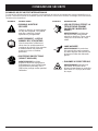
SYMBOL MEANING
• SAFETY ALERT SYMBOL
Indicates danger, warning or caution.
May be used in conjunction with other
symbols or pictographs.
•WARNING - READ
OPERATOR'S MANUAL
Read the operator’s manual(s) and follow
all warnings and safety instructions.
Failure to do so can result in serious injury
to the operator and/or bystanders.
• WEAR EYE AND HEARING
PROTECTION
WARNING: Thrown objects and loud
noise can cause severe eye injury and
hearing loss. Wear eye protection
meeting ANSI Z87.1 standards and ear
protection when operating this unit.
Use a full face shield when needed.
SYMBOL MEANING
• THROWN OBJECTS AND
ROTATING CUTTER CAN
CAUSE SEVERE INJURY
WARNING: Do not operate without
the cutting attachment shield in place.
Keep away from the rotating cutting
attachment.
• SHARP BLADE
WARNING: Sharp blade on cutting
attachment shield. To prevent serious
injury, do not touch line cutting blade.
• KEEP BYSTANDERS AWAY
WARNING: Keep all bystanders,
especially children and pets, at least
50 feet (15 m) from the operating area.
SAFETY AND INTERNATIONAL SYMBOLS
This operator's manual describes safety and international symbols and pictographs that may appear on this product.
Read the operator's manual for complete safety, assembly, operating and maintenance and repair information.
RULES FOR SAFE OPERATION

6
APPLICATIONS
As a trimmer:
• Cutting grass and light weeds
• Decorative trimming around trees, fences, etc.
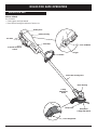
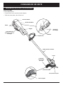
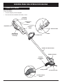
KNOW YOUR UNIT
RULES FOR SAFE OPERATION
Motor Housing
D-handle
Line Cutting Blade
Bump Knob
Trigger
Lock-Off Button
Bump Head
Cutting Attachment
Motor Wire Housing Tube
Hand Grip
Overload Protection
Switch
Battery Housing
Cutting
Attachment
Shield
Battery Door
Air Vents

7
ASSEMBLY INSTRUCTIONS
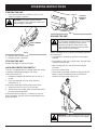
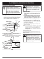
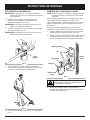
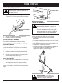
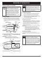
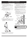
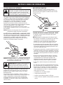
3. Plug the charger into the wall outlet and wind any
excess wire onto the cord wrap on the charging
station (Fig. 3).
Wall Outlet
Charging Station
Screws
Wall
Stud
Cord Wrap
Charger
Fig. 3
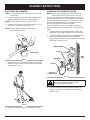
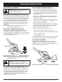
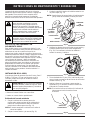
ADJUSTING THE D-HANDLE
NOTE: The D-handle comes mounted on the backside
of the shaft.
Fig. 1
Fig. 2
MOUNTING THE CHARGING STATION
NOTE: Mount the charging unit and allow the unit to
charge for at least 36 hours prior to first use.
This unit may stay on the charging station continuously
without overcharging. Place the charging station where
the unit is intended to be stored. This should be a cool,
dry and well ventilated place, where the unit can be
locked-up and out of the reach of children.
The unit should be stored and charged in a location
where the temperature is between 50˚F (10˚C) and 100˚F
(38˚C).
1. Locate a place for the charging station near a wall
outlet and high enough to keep the unit off the floor.
2. Locate the wall stud and mount the charging station
to the wall using the three (3) screws provided
(Fig 3). Make sure that the screws enter the wall stud
to provide a secure mount.
Charging
Indicator Light
CAUTION: To prevent injury or damage to
the unit, the charging station must be
mounted securely to the wall.
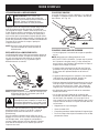
1. Locate the wing nut on the D-Handle. Untighten the
wing nut enough to loosen the D-Handle (Fig. 1).
NOTE: Do not remove wing nut, washer, or bolt.
2. Rotate the D-Handle to the upright position on the
front side of the shaft housing (Fig. 1).
NOTE: The D-handle should slant towards the
powerhead of the unit.
3. Hold the unit in the operating position. If necessary,
reposition the D-handle to the location that provides
the best grip (Fig. 2).
Wing Nut
4. Tighten the wing nut until the D-Handle is secure.

8
OPERATING INSTRUCTIONS
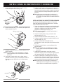
2. When the red indicator light on the charger is on, the
battery is being charged (Fig. 5). If the light fails to
come on, check that:
a. The charger is plugged into a working wall outlet.
b. The unit is firmly seated into the charging station and
the barrel connector is fully inserted into the unit.
c. The barrel connector is properly installed in the
charging station. If it isn’t, refer to Replacing the
Charger.
d. Power is on at the wall outlet.
NOTE: If the wall outlet is operated by a switch, be sure
the switch is ON.
Air Vents
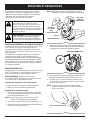
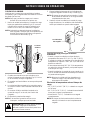
CHARGING THE UNIT
Make sure the charging station is securely fastened to a
wall and the charger is plugged into a working wall
outlet.
NOTE: Allow the unit to charge for at least 36 hours
prior to first use.
1. Slide the unit down into the charging station until it is
firmly seated (Fig. 4). The barrel connector in the
charging station will insert into the unit. If it doesn’t,
refer to Replacing the Charger.
NOTE: The battery will heat up while the unit charges.
Be sure the air vents on the battery housing are
kept clear for proper ventilation (Fig. 4).
Charging Tips for Maximum Performance
• Store and charge the unit where temperatures are
between 50˚ F (10˚ C) and 100˚ F (38˚ C). Storing the
unit or batteries above 100˚ F (38˚ C) will reduce
battery life.
• Storage below 50˚ F (10˚ C) will not reduce battery
life, but may require a longer charging time.
• Store the unit on the charging station when not in
use. The unit is designed so that the battery cannot
be overcharged.
NOTE: The charging indicator light will remain lit when
the unit is properly installed in the charging
station.
Temperature Effects on Charging Time
• 50˚ F (10˚ C) to 100˚ F (38˚ C) – Battery will charge
within 24 hours.
• 40˚ F (4 ˚C) to 50˚ F (10˚ C) – Battery will require up to
48 hours for a full charge.
• Below 40˚ F (4 ˚C) – Battery will not reach full charge.
NOTE: The unit run time will be reduced when the
battery is not fully charged.
Fig. 4
Charging
Station
Barrel
Connector
Fig. 5
Charging
Indicator Light
3. Charge the battery until the Charging Indicator Light
on the charger turns from red to green (Fig. 5).
NOTE: The unit’s operating time and the life of the
battery will be shorten if the unit is not fully
charged between uses.
4. Place the unit back on the charging station after
each use. The unit is designed so that the battery
cannot be overcharged.
WARNING: If the wall outlet is not working
properly, have the wall outlet checked by a
qualified electrician. This will help prevent
serious personal injury.

9
OPERATING INSTRUCTIONS
WARNING: To prevent serious injury, do not
carry the unit with your finger on the trigger.
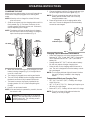
HOLDING THE UNIT
Before operating the unit, stand in the operating position
and check that:
• The operator is wearing eye protection and proper
clothing.
• The operator’s right arm is slightly bent, the right hand
holding the housing grip.
•With a straight left arm, the left hand holding the
D-handle.
• The unit is at waist level.
• The trimmer bump head is parallel to the ground and
easily contacts the material to be cut without the
operator having to bend over (Fig. 8).
Fig. 8
2. Depress and hold the trigger.
3. Release the lock-off button.
STOPPING THE UNIT
Release the trigger to stop the trimmer.
STARTING THE UNIT
1. Press and hold the lock-off button in (Fig. 6). This
allows the trigger to operate.
Fig. 6
Lock-Off Button
Fig. 7
Overload
Protection
Switch
Trigger
OVERLOAD PROTECTION SWITCH
This unit is equipped with an overload protection switch
to prevent overheating damage to the motor.
If the switch pops out:
1. Release the trigger and allow the unit to cool for a
minute.
2. Press the overload switch to reset. Resume
operation (Fig. 7).
If the switch pops again shortly after the first time:
1. Allow the unit to cool for 15 to 30 minutes.
2. After the unit has cooled, press the overload switch
to reset. Resume operation
If the switch does not stay in or continues to pop out
during operation, take the unit to an authorized service
dealer for repair.
WARNING: Dress properly to reduce the risk
of injury when operating this unit. Do not wear
loose clothing or jewelry. Wear eye and
ear/hearing protection. Wear heavy, long
pants, boots and gloves. Do not wear short
pants, sandals or go barefoot.
WARNING: To prevent serious personal
injury, ensure the lock-off button resets each
time the trigger is released.

10
OPERATING INSTRUCTIONS
TIPS FOR BEST TRIMMING RESULTS
• Keep the cutting attachment parallel to the ground.
• Do not force the cutting attachment. Allow the tip of the
line to do the cutting, especially along walls. Cutting with
more than the tip will reduce cutting efficiency and may
overload the motor.
• Cut grass over 8 inches (200 mm) by working from top
to bottom in small increments to avoid premature line
wear or motor drag.
• Cut from right to left whenever possible. Cutting to the left
improves the unit's cutting efficiency. Clippings are
thrown away from the operator.
• Slowly move the trimmer into and out of the cutting
area at the desired height. Move either in a forward-
backward or side-to-side motion. Cutting shorter
lengths produces the best results.
• Trim only when grass and weeds are dry.
• The life of your cutting line is dependent upon:
• Following the trimming techniques previously explained
• What vegetation is cut
• Where vegetation is cut
For example, the line will wear faster when trimming against
a foundation wall as opposed to trimming around a tree.
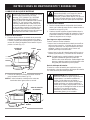
DECORATIVE TRIMMING
Decorative trimming is accomplished by removing all
vegetation around trees, posts, fences and more.
Rotate the whole unit so that the cutting attachment is at
a 30° angle to the ground (Fig. 10).
NOTE: Always keep the trimming line fully extended.
Line release becomes more difficult as cutting
line becomes shorter.
Each time the head is bumped, approximately 1 inch
(25.4 mm) of trimming line is released. A blade in the
string guard will cut the line if excess line is released.
For best results, tap the head on bare ground or hard
soil. If line release is attempted in tall grass, the motor
may overheat. Always keep the trimming line fully
extended. Line release becomes more difficult as the
cutting line becomes shorter.
Fig. 9
Bump Head
OPERATING THE TRIMMER
Clear the area to be cut before each use. Remove all
objects such as rocks, broken glass, nails, wire, or string
which can be thrown or become entangled in the cutting
attachment. Clear the area of children, bystanders, and
pets. At a minimum, keep all children, bystanders and
pets outside a 50 feet (15m) radius; there still may be a
risk to bystanders from thrown objects. Bystanders
should be encouraged to wear eye protection. If you are
approached, stop the motor and cutting attachment
immediately.
NOTE: Remove protective tape from the line cut-off
blade before operating trimmer.
ADJUSTING TRIMMING LINE LENGTH
The bump head allows the operator to release more
trimming line without stopping the motor. As line
becomes frayed or worn, additional line can be released
by lightly tapping the trimming head on the ground while
operating the trimmer (Fig. 9).
CAUTION:
Do not remove or alter the line
cutting blade assembly. Excessive line length will
make the unit overheat. This may lead to serious
personal injury or damage to the unit.
WARNING: Always wear eye, hearing, foot
and body protection to reduce the risk of
injury when operating this unit.
Fig. 10

11
MAINTENANCE AND REPAIR INSTRUCTIONS
SERVICING DOUBLE INSULATED UNITS
This unit is double-insulated. In a double-insulated unit,
two systems of insulation are provided instead of
grounding. There is no grounding provided and no
means of grounding should be added to this unit.
Extreme care and knowledge of the system is required
when servicing a double-insulated unit. Service should
be performed by qualified service personnel only.
Replacement parts for a double-insulated unit must be
identical to the parts they replace. Refer any repair to an
authorized service dealer. A double-insulated unit is
marked with the words “double insulation” or “double
insulated.”
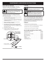
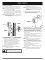
LINE INSTALLATION
Always use genuine Genuine Factory Parts™ 0.080 in.
(2.03 mm.) replacement line. Using line other than
specified may cause the unit to overheat or fail.
There are two methods to replace the trimmer line:
•Wind the inner reel with new line
• Install a prewound inner reel
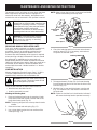
Winding the Existing Reel
1. Remove the bump head cover by pressing in both
bump head cover tabs visible on either side of the
bump head outer spool (Fig. 11).
NOTE: The spring will push the cover up when the tabs
release.
2. Remove the inner reel and spring (Fig. 11).
3. Use a clean cloth to wipe the inner surface of the
outer spool (Fig. 11).
WARNING: Never use metal-reinforced line,
wire, chain or rope. These can break off and
become dangerous projectiles.
WARNING: To prevent serious personal
injury, remove or disconnect the battery
before servicing, cleaning or removing
material from the unit.
WARNING: Battery tools do not have to be
plugged into an electrical outlet; therefore, they
are always in operating condition. To prevent
serious personal injury, take extra precautions
and care when cleaning, performing
maintenance and service, or when changing
the cutting attachment or other attachments.
The warranty on this unit does not cover items that have
been subjected to operator abuse or negligence. To
receive full value from the warranty, the operator must
maintain the unit as instructed in this operator’s manual.
Outer Spool
Spring
Inner Reel
Press Tabs
Bump Head
Cover
Fig. 11
Indexing Teeth
Inner Reel Hole
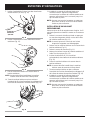
4. Check the indexing teeth on the inner reel and outer
spool for wear (Fig. 12). If necessary, remove burrs
or replace the reel and spool.
NOTE: Always clean the inner reel, outer spool and shaft
before reassembling the bump head.
5. Take approximately 12 feet (3.6 m) of new trimming
line and insert one end of the line into the hole in the
inner reel (Fig. 13).
6. Wind the line, in even and tight layers, onto the reel
(Fig. 13). Wind the line in the direction indicated on
the inner reel.
NOTE: Failure to wind the line in the direction indicated
will cause the bump head to operate incorrectly.
Fig. 12
Fig. 13

12
MAINTENANCE AND REPAIR INSTRUCTIONS
11. Install the bump head cover over the inner reel. Align
the tabs on the cover with the slots in the outer
spool and press the cover evenly down until it snaps
into place.
NOTE: Make sure the bump head cover tabs snap into
place or the inner reel will come out during
operation.
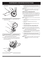
8. Insert the end of the line through the eyelet in the
outer spool (Fig. 15).
INSTALLING A PREWOUND REEL
Always use genuine replacement line. Using larger line
then the specified may make the motor overheat or fail.
1. Remove the bump head cover by pressing in both
bump head cover tabs visible on either side of the
bump head outer spool (Fig. 11).
NOTE: The spring will push the cover up when the tabs
release.
2. Remove the old inner reel and spring from the outer
spool (Fig. 11).
3. Remove the spring from the old inner reel
(Fig. 11).
4. Use a clean cloth to wipe the inner surface of the
outer spool (Fig. 12).
5. Insert the end of the line, on the prewound reel,
through the eyelet in the outer spool (Fig. 15).
6. Place inner reel and spring inside the outer spool.
NOTE: The spring must be assembled on the inner reel
before reassembling the bump head.
7. Hold the inner reel in place, grasp the line end and
pull firmly to release the line from the holding slot in
the inner reel (Fig. 16).
8. Install the bump head cover over the inner reel. Align
the tabs on the cover with the slots in the outer
spool and press the cover evenly down until it snaps
into place.
NOTE: Make sure the bump head cover tabs snap into
place or the inner reel will come out during
operation.
9. Place inner reel and spring inside the outer spool.
NOTE: The spring must be assembled on the inner reel
before reassembling the bump head.
10. Hold the inner reel in place, grasp the line end and
pull firmly to release the line from the holding slot in
the inner reel (Fig. 16).
Fig. 15
Fig. 16
7. Insert the end of the line into one of the two holding
slots (Fig. 14).
Fig. 14
Holding
Slot

13
WARNING: If the battery pack has signs of
leakage, do not touch. Do not open or
mutilate the battery. Released electrolyte is
corrosive and may cause damage to the eyes
or skin. To avoid serious injury, take the unit
to an authorized service dealer for repair.
BATTERY PACK REPLACEMENT
Removing the Battery
1. Push the two latches on the side of the battery housing
door in and swing the door down. Unhook the door
from the slot on the bottom of the battery housing by
lifting up and away. Set the door aside (Fig. 17).
Fig. 17
Fig. 18
Installing the Battery
1. Slide the battery into the battery housing until the
battery retaining latch locks the battery into place
(Fig 18).
2. Reinstall the door by hooking over the slot on the
bottom of the battery housing. Swing the battery
housing door closed until the two latches snap into
place.
For best performance when reinstalling the battery:
• Check the battery terminals for corrosion and clean
them if necessary. Clean the terminals using a dry
scrubbing pad and wipe clean with a dry cloth. Never
use liquids to clean terminals.
• Check the battery casing for signs of damage and
replace it if needed.
NOTE: If you clean or replace the battery, apply a small
amount of electrically conductive grease to the
terminals only. This grease is available at any
local electronics store. Do not use automotive or
bearing grease.
Storing the Battery Pack
If you are removing the battery for replacement or for
storage, cover the battery pack’s terminals with heavy
duty electrical tape.
Latches
Hook
Battery
Retaining Latch
Door
Battery
Battery Housing
2. Push down on the battery retaining latch while
pulling battery out (Fig. 18).
NOTE: You might notice grease on the terminal contacts
when the battery is removed. This is normal.
MAINTENANCE AND REPAIR INSTRUCTIONS
To preserve natural resources, please recycle
or dispose of properly. THIS PRODUCT
CONTAINS A SEALED LEAD-ACID BATTERY
AND MUST BE DISPOSED OF PROPERLY.
Local, state, or federal laws may prohibit
disposal of sealed lead-acid batteries in
ordinary trash. Consult your local waste
authority for information regarding available
recycling and/or disposal options.
WARNING: Do not attempt to destroy or
disassemble battery or remove any of its
components. Sealed lead-acid batteries must
be recycled or disposed of properly. Never
touch both terminals with metal objects
and/or body parts, a short circuit may result.
Keep away from children. Failure to comply
with these warnings could result in fire and/or
serious personal injury.

14
CLEANING
Switch off the unit and disconnect it from the power
source. Use a small brush to clean off the outside of the
unit. Do not use strong detergents. Household cleaners
that contain aromatic oils such as pine and lemon, and
solvents such as kerosene, can damage plastic housing
or handle. Wipe off any moisture with a soft cloth. Also
keep the air vents free of obstructions.
STORAGE
• Allow the unit to cool before storing.
• Lock the unit to prevent unauthorized use or damage.
• Store the unit in a dry, well-ventilated area.
• Store the unit out of the reach of children.
MAINTENANCE AND REPAIR INSTRUCTIONS
WARNING: To avoid serious personal injury,
always turn your trimmer off and remove the
battery before you clean or service it.
REPLACING THE CHARGER
Replace the charger if it is damaged, if the barrel
connector or cord become damaged, or if the barrel
connector is not contacting the unit properly.
Your trimmer requires a 12V charger (182534) and
charging station (180295). The charging instructions
refer only to these parts.
1. Unplug the charger from the wall outlet and remove
the unit from the charging station.
2. Remove the screw from the clamp holding the barrel
connector in place using a standard or T-20 Torx bit
screwdriver (Fig. 19).
3. Remove the barrel connector from the slot and
replace the charger, if needed.
4. Insert the narrow side of the barrel connector wire
into the groove in the slot of the charging station.
Ensure that the barrel connector is inserted correctly
and secure (Fig. 19).
5. Reinstall the clamp and screw.
6. Plug the charger into the wall outlet. Refer to
Charging the Unit for charging instructions.
Barrel Connector
Clamp
Charging Station
Fig. 19
Edge of Barrel
Connector Wire
Groove
Charger
CAUTION: Only use the type of charger
specified for this unit. Any other type may
cause damage to the unit, damage to the
batteries or possible injury.
WARNING: Battery tools do not have to be
plugged into an electrical outlet; therefore,
they are always in operating condition. To
prevent serious personal injury, take extra
precautions and care when cleaning the unit.
ACCESSORIES AND REPLACEMENT PARTS
Cutting Attachment Shield . . . . . . . . . . . . . . . . . 180293
Replacement Line . . . . . . . . . . . . . . . . . . . . . . . 610375
Replacement Line Cartridge . . . . . . . . . . . . . . . . 180292
Inner Reel Spring . . . . . . . . . . . . . . . . . . . . . . . . 180374
Bump Head Cover . . . . . . . . . . . . . . . . . . . . . . . 180376
Charger . . . . . . . . . . . . . . . . . . . . . . . . . . . . . . . . 182534
Charging Station . . . . . . . . . . . . . . . . . . . . . . . . . 180295
12 Volt Battery Pack . . . . . . . . . . . . . . . . . . . . . . 182391

15
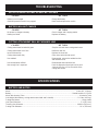
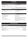
TROUBLESHOOTING
CAUSE ACTION
Cutting attachment bound with grass Stop the unit and clean cutting attachment
Cutting attachment out of line Refill with new line
Inner reel bound up Replace the inner reel
Cutting attachment dirty Clean inner reel and outer spool
Line welded Disassemble, remove the welded section
and rewind the line
Line twisted when refilled Disassemble and rewind the line
Not enough line is exposed Push the Bump Knob and pull out line until
4 inches (102 mm.) of line is outside of the
cutting attachment
CAUSE ACTION
Battery is not charged Charge the battery
Overload protection switch has popped Reset overload protection switch
MOTOR OPERATES SLOWLY OR WILL NOT OPERATE
BATTERY WILL NOT CHARGE
CAUSE ACTION
No power to charger or battery Check charger and charging station
Battery has failed Replace the battery
CUTTING ATTACHMENT WILL NOT ADVANCE LINE
SPECIFICATIONS
Motor.................................................................................................................................................. 12 Volt DC, 15 Amps
Battery......................................................................................................................................... Sealed Lead-Acid, 12 Volt
Motor Wire Housing Tube............................................................................................................................ Aluminum Tube
Unit Weight (With battery, cutting attachment shield and D-handle)...................................................... 10.2 lbs. (4.63 kg.)
Cutting Mechanism.............................................................................................................................................Bump Head
Line Spool Diameter...................................................................................................................................... 3 in (76.2 mm)
Trimming Line Diameter......................................................................................................................... 0.080 in (2.03 mm.)
Cutting Path Diameter................................................................................................................................. 10 in. (254 mm)
BATTERY AND MOTOR

16
MANUFACTURER’S LIMITED WARRANTY FOR:
No implied warranty, including any implied warranty of
merchantability or fitness for a particular purpose,
applies after the applicable period of express written
warranty above as to the parts as identified. No other
express warranty or guaranty, whether written or oral,
except as mentioned above, given by any person or
entity, including a dealer or retailer, with respect to any
product shall bind Troy-Bilt LLC During the period of
the Warranty, the exclusive remedy is repair or
replacement of the product as set forth above. (Some
states do not allow limitations on how long an implied
warranty lasts, so the above limitation may not apply to
you.)
The provisions as set forth in this Warranty provide the
sole and exclusive remedy arising from the sales. Troy-
Bilt LLC shall not be liable for incidental or
consequential loss or damages including, without
limitation, expenses incurred for substitute or
replacement lawn care services, for transportation or
for related expenses, or for rental expenses to
temporarily replace a warranted product. (Some states
do not allow limitations on how long an implied warranty
lasts, so the above limitation may not apply to you.)
In no event shall recovery of any kind be greater than the
amount of the purchase price of the product sold.
Alteration of the safety features of the product shall void
this Warranty. You assume the risk and liability for loss,
damage, or injury to you and your property and/or to
others and their property arising out of the use or misuse
or inability to use the product.
This limited warranty shall not extend to anyone other than
the original purchaser, original lessee or the person for
whom it was purchased as a gift.
How State Law Relates to this Warranty: This warranty
gives you specific legal rights, and you may also have
other rights which vary from state to state.
To locate your nearest service dealer dial
1-800-520-5520.
Troy-Bilt LLC
P.O. Box 361131
Cleveland, OH 44136-0019
The limited warranty set forth below is given by Troy-Bilt
LLC with respect to new merchandise purchased and used
in the United States, its possessions and territories.
Troy-Bilt LLC warrants this product against defects in
material and workmanship for a period of two (2) years
commencing on the date of original purchase and will, at its
option, repair or replace, free of charge, any part found to
be defective in material or workmanship. This limited
warranty shall only apply if this product has been operated
and maintained in accordance with the Operator’s Manual
furnished with the product, and has not been subject to
misuse, abuse, commercial use, neglect, accident,
improper maintenance, alteration, vandalism, theft, fire,
water or damage because of other peril or natural disaster.
Damage resulting from the installation or use of any
accessory or attachment not approved by Troy-Bilt LLC for
use with the product(s) covered by this manual will void
your warranty as to any resulting damage. This warranty is
limited to ninety (90) days from the date of original retail
purchase for any Troy-Bilt product that is used for rental or
commercial purposes, or any other income-producing
purpose.
HOW TO OBTAIN SERVICE: Warranty service is
available, WITH PROOF OF PURCHASE THROUGH
YOUR LOCAL AUTHORIZED SERVICE DEALER. To locate
the dealer in your area, visit our website at www.troybilt.com,
check for a listing in the Yellow Pages, call 1-800-520-
5520 or write to
P.O. Box 361131, Cleveland, OH 44136-
0019
.
This limited warranty does not provide coverage in
the following cases:
A. Tune-ups - Spark Plugs, Carburetor Adjustments,
Filters
B. Wear items - Bump Knobs, Outer Spools, Cutting
Line, Inner Reels, Starter Pulley, Starter Ropes, Drive
Belts
C. Troy-Bilt LLC does not extend any warranty for
products sold or exported outside of the United
States of America, its possessions and territories,
except those sold through Troy-Bilt’s authorized
channels of export distribution.
Troy-Bilt LLC reserves the right to change or improve the
design of any Troy-Bilt Product without assuming any
obligation to modify any product previously manufactured.

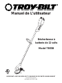
Désherbeuse à
batterie de 12 volts
Model TB55B
P/N 769-00532 (12/02)
IMPRIME AUX ÉTATS-UNIS
Manuel de L’utilisateur
IMPORTANT : LISEZ LES RÈGLES ET CONSIGNES DE SÉCURITÉ SOIGNEUSEMENT

F2
TABLE DES MATIÈRES
Contenu Page
Service technique . . . . . . . . . . . . . . . . . . . . . . . . . . . . . . . . . . . . . . . . . . . . . . . . . . . . . . . . F2
Consignes de sécurité. . . . . . . . . . . . . . . . . . . . . . . . . . . . . . . . . . . . . . . . . . . . . . . . . . . . . F3
Familiarisez-vous avec votre appareil . . . . . . . . . . . . . . . . . . . . . . . . . . . . . . . . . . . . . . . . . F6
Instructions de montage . . . . . . . . . . . . . . . . . . . . . . . . . . . . . . . . . . . . . . . . . . . . . . . . . . . F7
Mode d'emploi. . . . . . . . . . . . . . . . . . . . . . . . . . . . . . . . . . . . . . . . . . . . . . . . . . . . . . . . . . . F8
Entretien et réparations . . . . . . . . . . . . . . . . . . . . . . . . . . . . . . . . . . . . . . . . . . . . . . . . . . . F11
Nettoyage et entreposage. . . . . . . . . . . . . . . . . . . . . . . . . . . . . . . . . . . . . . . . . . . . . . . . . F14
Accessoires/pièces de rechange. . . . . . . . . . . . . . . . . . . . . . . . . . . . . . . . . . . . . . . . . . . . F14
Tableau de dépannage . . . . . . . . . . . . . . . . . . . . . . . . . . . . . . . . . . . . . . . . . . . . . . . . . . . F15
Caractéristiques. . . . . . . . . . . . . . . . . . . . . . . . . . . . . . . . . . . . . . . . . . . . . . . . . . . . . . . . . F15
Garantie. . . . . . . . . . . . . . . . . . . . . . . . . . . . . . . . . . . . . . . . . . . . . . . . . . . . . . . . . . . . . . . F16
Liste des Pièces . . . . . . . . . . . . . . . . . . . . . . . . . . . . . . . . . . . Intérieure de la Couverture Arrière
Ce manuel de l'utilisateur est un élément important de votre nouvelle désherbeuse/débroussailleuse. Il a été conçu pour
vous aider à assembler, préparer et faire l'entretien de l'appareil afin d'assurer des performances optimales. Prenez soin
de lire et comprendre son contenu.
Avant d'assembler votre nouvel équipement, repérez la plaque signalétique de l'appareil et copiez ses informations dans
l'espace ci-dessous. Ces informations sont essentielles si vous désirez obtenir de l'aide auprès de notre service
technique ou d'un distributeur agréé.
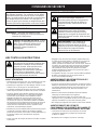
• Le numéro de modèle se trouve sur le côté du carter du moteur. Un exemple de plaque signalétique est présenté
ci-dessous. Veuillez copier le numéro de modèle et le numéro de série de l'équipement dans l'espace ci-dessous
afin de pouvoir vous y référer ultérieurement.
Si vous éprouvez des difficultés à assembler ce produit ou si vous avez des questions concernant les commandes, le
fonctionnement ou l'entretien de cet appareil, veuillez communiquer avec notre service technique.
Appelez le 1-800-520-5520 pour joindre un de nos représentants. Veuillez avoir les numéros de modèle et
de série de l'appareil à portée de main lorsque vous appelez. Reportez-vous à la section précédente pour
savoir où trouver ces informations. On vous demandera le numéro de série au moment de traiter votre
demande.
TROUVER LE NUMÉRO DE MODÈLE
SERVICE TECHNIQUE
Pour de plus amples informations à propos de votre appareil, visitez www.troybilt.com
S/N :
ITEM :
MODEL :
Numéro de modèle
Numéro de série
Numéro de pièce mère
Copiez le numéro de
modèle / pièce mère ici :
Copiez le numéro de série ici :

F3
CONSIGNES DE SÉCURITÉ
DANGER:
le non-respect d’un avertissement
peut causer dommages matériels ou
blessures graves pour tous. Respectez les
consignes de sécurité afin de réduire les
risques d'incendie, d'électrocution et de
blessures.
AVERTISSEMENT: le non-respect d’un
avertissement peut causer dommages
matériels ou blessures graves pour tous.
Respectez les consignes de sécurité afin de
réduire les risques d'incendie, d'électrocution
et de blessures.
MISE EN GARDE: le non-respect d’un
avertissement peut causer dommages
matériels ou blessures graves pour tous.
Respectez toujours les consignes de sécurité
afin de réduire les risques d'incendie,
d'électrocution et de blessures.
SYMBOLE ALERTE DE SÉCURITÉ : indique
un danger, un avertissement ou une mise en
garde. Soyez vigilant afin d'éviter toute
blessure grave. Ce symbole peut être
combiné à d'autres symboles ou
pictogrammes.
SYMBOLE SIGNIFICATION
Les symboles de sécurité attirent votre attention sur
des dangers potentiels. Ces symboles et leurs détails
explicatifs méritent que vous les lisiez et compreniez
bien. Les avertissements de sécurité ne peuvent éviter
les dangers de par eux-mêmes. Les consignes ou
mises en garde qu'ils donnent ne remplacent pas des
mesures préventives appropriées contre les accidents.
REMARQUE: donne des informations ou des
instructions vitales pour le fonctionnement ou
l'entretien de l'équipement.
SYMBOLE SIGNIFICATION
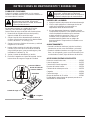
AVANT UTILISATION
• Veuillez lire les instructions avec soin. Familiarisez-vous avec
les commandes et l'utilisation correcte de cet appareil.
• N'utilisez pas l'appareil si vous êtes fatigué, malade ou sous
l'effet de l'alcool, de drogues ou de médicaments.
•
Les enfants et adolescents de moins de 15 ans ne doivent pas
utiliser l'appareil exceptés les adolescents assistés d'un adulte.
• Inspectez l'appareil avant utilisation. Remplacez les pièces
endommagées.
Recherchez s'il y a des fuites de batterie.
Assurez-vous que les fixations sont solidement en place.
Remplacez les pièces de l'accessoire de coupe qui sont
fendillées, ébréchées ou endommagées. Assurez-vous que
l'accessoire de coupe est correctement installé et solidement
fixé. Assurez-vous que le protecteur d'accessoire de coupe est
correctement fixé et positionné comme recommandé. Vous
risquez sinon de causer des blessures à l'opérateur et aux
spectateurs, et d'endommager l'appareil.
• N'utilisez que du fil de remplacement Genuine Factory Parts
MC
d'origine de 2,03 mm (0,080 po) de diamètre. N'utilisez
jamais de fil, de chaîne ou de cordon à renfort métallique car
ils peuvent se briser et se transformer en projectile
dangereux.
• Soyez conscient des risques de blessure à la tête, aux mains
et aux pieds.
• Dégagez la zone de coupe avant chaque usage. Enlevez tous
les objets pouvant être projetés ou happés par l'accessoire de
coupe : cailloux, verre brisé, clous, fil ou ficelle. Éloignez
enfants, spectateurs et animaux de la zone de coupe. Tenez-les
à au moins 15 m (50 pi) de là mais sachez que les spectateurs
risquent quand même d'être atteints par des objets projetés.
Les spectateurs doivent porter des protections oculaires.
Arrêtez immédiatement le moteur et l'accessoire de coupe si
quelqu'un s'approche de vous.
• Cet appareil n'est pas conçu pour servir de débroussailleuse.
N'utilisez cet appareil avec aucun type de lame ou
d'accessoire de débroussaillage.
AVERTISSEMENTS DE SÉCURITÉ POUR LES
DÉSHERBEUSES À BATTERIE
• Il n’est pas nécessaire de brancher dans une prise les outils à
batterie, ils peuvent donc fonctionner à tout moment. Pensez
aux dangers potentiels même si l’outil ne fonctionne pas.
Faites attention lorsque vous effectuez l'entretien ou la
maintenance.
• Enlevez ou déconnectez la batterie avant tout entretien,
nettoyage ou retrait de pièces de l’appareil.
• Utilisez uniquement la station de charge fournie avec
l'appareil. Si vous y substituez un autre, vous risquez de faire
exploser les batteries et causer des blessures graves.
• Ne chargez pas l’appareil sous la pluie ou dans un lieu humide.
AVERTISSEMENTS DE SÉCURITÉ
CONCERNANT LES SUPPORTS DE CHARGE ET
LES BATTERIES RECHARGEABLES AU PLOMB
• Lisez toutes les instructions et précautions du manuel
concernant l’appareil et son support de charge avant
d’utiliser ce dernier.
• N’exposez pas le chargeur à la pluie ou à la neige.
AVERTISSEMENT: Respectez toujours les
consignes de sécurité durant l’utilisation des
désherbeuses à batterie afin de réduire les
risques d’incendie, d’électrocution et de
blessures. Prenez soin de bien lire et
comprendre tout le manuel de l’utilisateur
avant d’utiliser la désherbeuse. Faites
particulièrement attention au mode d'emploi
et aux avertissements de sécurité.
LIRE TOUTES LES INSTRUCTIONS

F4
• Afin de réduire les risques de blessures, ne chargez que les
batteries hermétiques rechargeables au plomb. Les autres
types de batteries peuvent exploser et causer des blessures
et des dommages.
• Pour réduire le risque de choc électrique, cet appareil est
pourvu d’une fiche polarisée (une lame est plus large que
l’autre). Cet appareil ne être inséré dans une prise polarisée que
d’une seule manière. S’il n’est pas possible d’insérer
entièrement la fiche dans la prise, essayez de brancher la fiche
dans l’autre sens. Si malgré tout, il n’est pas possible d’insérer
la fiche, remplacez le cordon par un cordon qui comporte les
bonnes fiches. Ne modifiez cet appareil en aucun cas.
• Pour éviter d’endommager le corps du chargeur et son cordon,
tirez sur le premier au moment de débrancher le chargeur.
• Placez le cordon du chargeur de façon qu’il ne soit pas
piétiné, accroché ou endommagé d’une manière quelconque.
• N'utilisez pas le chargeur si le cordon ou la prise est
endommagée, sinon remplacez-les immédiatement.
• N’utilisez pas le chargeur s’il a reçu un coup dur, est tombé
ou a été endommagé. Si le boîtier du chargeur est
endommagé, remplacez le chargeur.
• Ne démontez par le chargeur car il n'est pas conçu pour cela
et vous risquez de provoquer l'électrocution ou un incendie.
• Pour diminuer les risques d’électrocution, débranchez le
chargeur de la prise avant tout entretien ou nettoyage.
• N'utilisez pas le chargeur en plein air.
• Utilisez uniquement une batterie de type et de format suivants
: batterie hermétique rechargeable de 12 volts c.c.
• Ne jetez pas la batterie dans le feu car ses éléments
pourraient exploser. Recyclez la batterie. Consultez à ce
sujet vos responsables locaux en matière de recyclage et de
mise au rebut.
• Ne chargez pas la batterie sous la pluie ou dans un lieu
humide.
• Manipulez la batterie avec soin afin de ne pas provoquer de
court-circuit avec des objets conducteurs tel que des anneaux,
des bracelets ou des clés. La batterie ou l’objet conducteur
pourrait en effet surchauffer et causer des brûlures.
• Chargez la batterie dans un endroit où la température se
situe entre 10ºC (50ºF) et 38ºC (100ºF).
• Évitez d’ouvrir ou d’endommager la batterie. Une fois
relâché, l’électrolyte, qui est corrosif, peut endommager les
yeux ou la peau. Il peut aussi être toxique s’il est avalé.
PENDANT L'UTILISATION
• Pour éviter tout démarrage accidentel, ne transportez jamais
l’appareil le doigt sur la détente.
• Portez des lunettes de sécurité conformes aux normes ANSI
Z87.1-1989 ainsi que des protège-oreilles durant l'utilisation. En
cas de poussière, portez un masque facial ou antipoussières.
Les chemises à manches longues sont conseillées.
• Restez en alerte. Faites attention à ce que vous faites. Faites
preuve de bon sens.
• Portez des pantalons épais et longs, des bottes et des gants.
Ne marchez pas pieds nus et évitez les pantalons courts et
les sandales.
• Habillez-vous correctement. Ne portez pas de vêtements
lâches ni de bijoux pour éviter qu’ils ne soient happés par
des pièces mobiles. Relevez les cheveux au-dessus des
épaules.
• Ajustez la poignée en D selon votre taille pour mieux
l'agripper.
• N'utilisez l'appareil qu'en plein jour ou avec un bon éclairage
artificiel.
• Utilisez les outils appropriés. N'employez cet outil que pour
son usage prévu.
• Ne vous étirez pas. Tenez-vous toujours en équilibre.
• Ne forcez pas l’appareil. Il fonctionnera mieux et posera
moins de risques de blessures à la vitesse pour laquelle il a
été conçu.
• Tenez toujours l'appareil des deux mains lorsqu’il est en
marche. Agrippez fermement la poignée du boîtier de batterie
et la poignée en D.
• N'utilisez que des pièces de équipement original rechange et
accessoires Genuine Factory Parts
MC
d'origine pour cet appareil.
Elles sont disponibles auprès de votre concessionnaire agréé.
L'utilisation de pièces ou accessoires autres que ceux de
éqiupement original peut causer des blessures graves,
endommager l’appareil et annuler sa garantie.
• La désherbeuse est conçue pour couper l'herbe et les
mauvaises herbes légères, et pour la taille décorative. Ne
l’utilisez pas comme coupe-bordure.
• Avant de démarrer l'appareil, assurez-vous que l'accessoire
de coupe ne touche aucun objet.
• Si vous heurtez ou happez un corps étranger, arrêtez
l’appareil immédiatement et vérifiez qu’il n’est pas
endommagé. Réparez les dommages avant de continuer.
N’utilisez pas l'appareil avec des pièces desserrées ou
endommagées.
• Relâchez la manette, mettez le bouton de verrouillage et
laissez le moteur s'arrêter en cas d’entretien ou de
réparation.
• Gardez les mains, le visage et les pieds éloignés des pièces
mobiles. Ne touchez pas ni essayez d'arrêter l'accessoire de
coupe en rotation.
• Arrêtez toujours le moteur lors d’une interruption ou si vous
vous déplacez d'un lieu de coupe à l’autre.
• Le protecteur d'accessoire de coupe doit toujours être mis
lors de l'utilisation de l'appareil. N’utilisez pas l'appareil sans
que le fil, de type approprié, soit bien déployé. Assurez-vous
que le fil ne dépasse pas le protecteur de sécurité.
• Gardez l'appareil exempt d'accumulation de végétation ou
autres matières. Celles-ci peuvent rester logées entre
l'accessoire de coupe et le protecteur.
AUTRES AVERTISSEMENTS DE SÉCURITÉ
• Laissez le moteur se refroidir avant de l'entreposer ou de le
transporter. Attachez bien l'appareil pendant le transport.
• Rangez l'appareil dans un endroit verrouillé et sec, ou élevé
et sec, hors de portée des enfants, pour éviter une utilisation
indésirable ou un accident.
• Ne trempez et n'arrosez jamais l'appareil avec de l'eau ou
tout autre liquide. Gardez les poignées sèches, propres et
exemptes de débris. Nettoyez après chaque usage. Voir les
sections Nettoyage et Entreposage.
• Conservez ces instructions. Consultez-les souvent et
servez-vous en pour instruire d'autres usagers. Si vous
prêtez l'appareil à quelqu'un, prêtez-lui également ces
instructions.
CONSERVEZ CES INSTRUCTIONS
CONSIGNES DE SÉCURITÉ
La page charge ...
La page charge ...
La page charge ...
La page charge ...
La page charge ...
La page charge ...
La page charge ...
La page charge ...
La page charge ...
La page charge ...
La page charge ...
La page charge ...
La page charge ...
La page charge ...
La page charge ...
La page charge ...
La page charge ...
La page charge ...
La page charge ...
La page charge ...
La page charge ...
La page charge ...
La page charge ...
La page charge ...
La page charge ...
La page charge ...
La page charge ...
La page charge ...
La page charge ...
La page charge ...
La page charge ...
La page charge ...
-
 1
1
-
 2
2
-
 3
3
-
 4
4
-
 5
5
-
 6
6
-
 7
7
-
 8
8
-
 9
9
-
 10
10
-
 11
11
-
 12
12
-
 13
13
-
 14
14
-
 15
15
-
 16
16
-
 17
17
-
 18
18
-
 19
19
-
 20
20
-
 21
21
-
 22
22
-
 23
23
-
 24
24
-
 25
25
-
 26
26
-
 27
27
-
 28
28
-
 29
29
-
 30
30
-
 31
31
-
 32
32
-
 33
33
-
 34
34
-
 35
35
-
 36
36
-
 37
37
-
 38
38
-
 39
39
-
 40
40
-
 41
41
-
 42
42
-
 43
43
-
 44
44
-
 45
45
-
 46
46
-
 47
47
-
 48
48
-
 49
49
-
 50
50
-
 51
51
-
 52
52


MTD TB55B Le manuel du propriétaire
- Catégorie
- Coupe-herbe
- Taper
- Le manuel du propriétaire
dans d''autres langues
- English: MTD TB55B Owner's manual
- español: MTD TB55B El manual del propietario