Electrolux EW30DS80RS Information produit
- Taper
- Information produit

NOTICE: This service data sheet is intended for use by persons having electrical and me-
chanical training and a level of knowledge of these subjects generally considered acceptable
in the appliance repair trade. The manufacturer cannot be responsible, nor assume any
liability, for injury or damage of any kind arising from the use of this data sheet.
IMPORTANT NOTE: This unit includes an EOC (electronic oven control). This board is not
eld-repairable.
Safe Servicing Practices
To avoid the possibility of personal injury and/or property damage, it is important that safe ser-
vicing practices be observed. The following are some, but not all, examples of safe practices.
1. Do not attempt a product repair if you have any doubts as to your ability to complete it
in a safe and satisfactory manner.
2. Before servicing or moving an appliance, remove power cord from electric outlet, trip
circuit breaker to Off, or remove fuse.
3. Never interfere with the proper installation of any safety device.
4. Use only replacement parts specied for this appliance. Substitutions may not comply
with safety standards set for home appliances.
5. Grounding: The standard color coding for safety ground wires is green or green with
yellow stripes. Ground leads are not to be used as current carrying conductors. It is
extremely important that the service technician reestablish all safety grounds prior to
completion of service. Failure to do so will create a potential hazard.
6. Prior to returning the product to service, ensure that:
• All electric connections are correct and secure.
• All electrical leads are properly dressed and secured away from sharp edges,
high-temperature components, and moving parts.
• All uninsulated electrical terminals, connectors, heaters, etc. are adequately
spaced away from all metal parts and panels.
• All safety grounds (both internal and external) are correctly and securely reas-
sembled.
• All panels are properly and securely reassembled.
IMPORTANT
DO NOT REMOVE THIS BAG
OR DESTROY THE CONTENTS
WIRING DIAGRAMS AND SERVICE
INFORMATION ENCLOSED
REPLACE CONTENTS IN BAG
p/n 807880710 EN (Rev A 16/02)
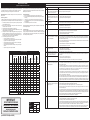
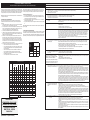
ELECTRONIC OVEN CONTROL (EOC) FAULT CODE DESCRIPTIONS
Note: Generally speaking “F1X” implies a control failure, “F3X” an oven probe problem, and “F9X” a latch motor problem.
Code Condition/Cause Suggested Corrective Action
F10 Control has sensed a potential runaway oven
condition. Control may have shorted relay, RTD
sensor probe may have a gone bad.
Check RTD sensor probe and replace if necessary. If oven is overheating, disconnect power. If oven continues to overheat when power
is reapplied, replace relay board and/or display board.
F11 Shorted Key: a key has been detected as
pressed for a long period and will be considered
a shorted key alarm and will terminate all
oven activity.
1. Press any key to clear the error.
2. If fault returns, replace the keyboard (touch panel).
3. If the problem persists, replace the display board.
F13 Control's internal checksum may have
become corrupted.
1. Press any key to clear the error.
2. Disconnect power, wait 30 seconds and reapply power. If fault returns upon power-up, replace display board.
F14 Misconnected keyboard cable 1. Verify connection between display board and touch panel (2 ribbon cables). Make sure the cables are well connected at both ends.
2. If the cables are good, replace the touch panel.
3. If the problem persists, replace the display board.
F15 Controller self check failed. 1. Verify if relay board receives 120VAC between J4 pin 1 and 3.
2. Verify the wiring between J2 on the relay board and P16 on the display board.
3. If wiring and 120VAC supply is good replace the display board.
4. If problem persists replace the relay board.
F20 The oven controller has detected a problem
with the communication link to the surface
element controller (ESEC).
1. Is the ESEC User Interface Board powered on (are the surface element displays showing something)? If not, that is the reason
why the oven control cannot communicate with it (ESEC has no power). Check the 120VAC voltage going in to the ESEC power
supply board located in the front console (connector P1) and the low voltage supply going from the power supply board (connector
P2) to the ESEC UIB (connector P8).
2. Check connections between connector P2 on the oven controller and P9 on the ESEC UIB. This is the communication link. Verify
for continuity. Refer to the wiring diagram.
3. If the above steps failed to solve the problem, replace the ESEC UIB.
4. If problem persists replace the oven controller.
F23 The controller failed to communicate with the
oven lights control board.
1. Verify wiring between P2 on the display board and P2 on the oven lights control board.
2. If wiring is good, replace oven lights board.
3. If the problem persists, replace the display board.
F30 Open RTD sensor probe/ wiring problem.
Note: EOC may initially display an “F10”,
thinking a runaway condition exists.
1. Check wiring in probe circuit for possible open condition.
2. Check RTD resistance at room temperature (compare to probe resistance chart). If resistance does not match the chart, replace the RTD
sensor probe.
3. Let the oven cool down and restart the function.
4. If the problem persists, replace the display board.
Note: F30 or F31 is displayed when oven is in active mode or an attempt to enter an active mode is made.
F31 Shorted RTD sensor probe / wiring problem.
F43 The cooling fan speed, as read by the
tachometer input of the EOC-display board,
is abnormally too slow.
1. Determine rst if the problem appears to be caused by a cooling fan not turning or turning slowly or by a problem with the sensing
of the fan speed. Start a Bake and check during the rst 15 seconds if the fan is turning (should feel air owing through the vent
above the upper oven door).
2. If the fan does not appear to be turning or turn slowly check the 120VAC at the fan. If 120VAC is present at the fan motor but the
fan does not turn replace the fan motor. If 120VAC is not present at the fan motor when a Bake is started check the connection
to the relay board (J3 pin 7) and Neutral: is there 120VAC on J3 pin 7? Does it reach the fan motor? Is the other terminal of the
fan motor connected to Neutral? If the harness or relay board are faulty replace them.
3. If the fan appears to be normally turning but an F43 error code is generated, it means there is a problem with the reading of the
fan speed sensor. Make sure the connection of the fan speed sensor is properly made (refer to wiring diagram), between the
sensor on the fan and the EOC- display board.
4. For trouble-shooting purposes, it is possible to enter a test mode that will indicate on the display the reading of the fan speed in
RPM: to enter the test mode, power-up the unit and within 30 seconds press and hold the upper oven Bake and Broil keys for 3
seconds (until you see all segments in the screen illuminated). Once in the test mode, pressing the upper oven Light key once will
display the fan speed in RPM. In normal client mode the F43 error is generated for a fan speed below approximately 700 RPM.
F44 The cooling fan speed, as read by the
tachometer input of the EOC- display board,
is abnormally too fast.
1. Inspect the cooling fan. Does it appear to be turning normally (air ow, noise)? Verify the fan blade is well assembled.
2. Verify there is nothing blocking the air ow of the fan (that could make the fan turn faster).
3. Check the 120VAC voltage on the fan. A voltage higher than 120VAC + 10% could make it go too fast.
4. Make sure the connection of the fan speed sensor is properly made (refer to wiring diagram), between the sensor on the fan
and the EOC- display board.
5. For trouble-shooting purposes, it is possible to enter a test mode that will indicate on the display the reading of the fan speed in RPM: to
enter the test mode, power-up the unit and within 30 seconds press and hold the upper oven Bake and Broil keys for 3 seconds (until you
see all segments in the screen illuminated). Once in the test mode, pressing the upper oven Light key once will display the fan speed in
RPM. In normal client mode the F44 error is generated for a fan speed above approximately 2500 RPM.
6. If problem persists replace both the fan+sensor assembly and the EOC- display board.
F90 Door motor mechanism failure. 1. Press any key to clear the error.
2. I
f it does not eliminate the problem, turn off power for 30 seconds, then turn on power.
3. Check wiring of Lock Motor, Lock Switch and Door Switch circuits.
4. Unplug the lock motor from the board and apply power (L1) directly to the Lock Motor. If the motor does not rotate, replace Lock Motor Assembly.
5. Check Lock Switch for proper operation (do they open and close, check with ohmmeter). The Lock Motor may be powered as in
above step to open and close Lock Switch. If the Lock Switch is defective, replace Motor Lock Assembly.
6. If all above steps fail to correct situation, replace the display board and/or the relay board in the event of a motor that does not rotate.
7. If all the above steps fail to correct the situation, replace the display board in the event of a motor that rotates endlessly.
SERVICE DATA SHEET
Appliance with ES630 Electronic Oven Control
Oven Calibration
Set the electronic oven control for normal baking at 350°F. Allow oven to preheat to set
temperature. Obtain an average oven temperature after a minimum of ve cycles. Press the
STOP key to end the Bake mode.
Temperature Adjustment
1. While in a non-cooking mode (idle), press User Pref key until UPO appears.
2. The current calibration offset (temperature adjustment) should appear in the tempera-
ture display.
3. Use the hi/lo (+/-) keys to enter the desired amount of adjustments (up to 35°F).
4. Once the desired adjustment (-35° to 35° F) has been entered, press the Start key to
accept the change.
5. Press the Cancel key to return the control to the idle.
Note: Changing calibration affects all baking modes. The adjustments made will not change
the self-cleaning temperature.
2-Speed Cooling Fan
The EOC controls the speed of the cooling fan. The cooling fan is activated at low speed
during any cooking function and will remain on until the oven is cooled down. The high speed
is activated during the broil (with open door) and during clean cycles only when the tempera-
ture is above apporximately 575°F/302°C.
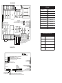
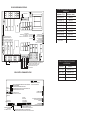
CIRCUIT ANALYSIS MATRIX
On Relay Board TRIAC Board On Display Board
ELEMENTS
Door
Motor
J3-5
DLB
L2 out
P1
Cooling
Fan
Low
J3-7
Cooling
Fan
High
J3-8
Door
Switch
P10-3
Rack
Sensor
Defeat
P10-2
Bake
P9
Broil
P7
Conv.
P11
Conv Fan
P2-7
Oven
Light
P2-1
Bake X X X* X X X X*
Keep Warm X X X
Broil X X X X
Conv. Bake X X X X X X X**
Conv. Roast X X X X X X X
Conv. Broil X X X X X
Clean X X X X X
Locking X
Locked
Unlocking X
Unlocked
Light X
Door Open X
Door Closed X
Bread Proof X X X
Rack sensor switch defeat X
Relay will operate in this condition only *Convection element and fan are used for the rst rise in temperature
LOWER
OVEN
ANALYSIS
MATRIX
On Relay Board
ELEMENTS DLB L2
out (P2)
Bake (P10)
Bake X X
Keep Warm X X

MEAT PROBE TEMPERATURE VS RESISTANCE TABLE
Temperature Probe Resistance
77 °F / 25°C 50.020 Kohm +/- 6%
122 °F / 50°C 18.020 Kohm +/- 5%
176 °F / 80°C 6.290 Kohm +/- 5%
212 °F / 100°C 3.400 Kohm +/- 5%
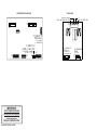
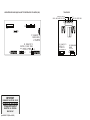
RELAY BOARD
OVEN CONTROL
Resistance (ohms)
1000 ± 4.0
1091 ± 5.3
1453 ± 8.9
1654 ± 10.8
1852 ± 13.5
2047 ± 15.8
2237 ± 18.5
2697 ± 24.4
Open circuit/infinite resistance
RTD SCALE
Temperature °F (°C)
32 ± 1.9 (0 ± 1.0)
75 ± 2.5 (24 ± 1.3)
250 ± 4.4 (121 ± 2.4)
350 ± 5.4 (177 ± 3.0)
450 ± 6.9 (232 ± 3.8)
550 ± 8.2 (288 ± 4.5)
650 ± 9.6 (343 ± 5.3)
900 ± 13.6 (482 ±7.5)
Probe circuit to case ground
P8 P10P12 P2 P4 P18
1
1
1
1
1
P7
P16
P15
P19
P13
P1P17P3P11
P9
J2 DC POWER
CONNECTS TO CONTROL P16
GROUND/TERRE
VLED (~+7 VDC)
VUR (~+15 VDC)
ZERO CROSS
J6 CONTROLS FAN,
NIGHT LIGHT, AUX
OUTPUT; CONNECTS
TO CONTROL P13
J5 - HEAT CONTROL OVEN
CONNECTS TO CONTROL P9
NEUTRAL/NEUTRE
L1
1
1
1
J4
J3
NEUTRAL/NEUTRE
L1
MDL/MOTEUR VERROU DE LA PORTE
COOLING FAN - LOW/VENT REFROID - BASSE
COOLING FAN - HIGH/VENT REFROID - HAUTE
BROIL
BAKE
CONVECTION ELEMENT/ÉLÉMENT DE CONVECTION
WARMER DRAWER ELEMENT/ÉLÉMENT DU TIROIR RÉCHAUD
GRIL
CUISSON
BAKE IGNITER/ALLUMEUR DU FOUR
BROIL IGNITER/ALLUMEUR DU GRIL
J2 DC ALIMENTATION
CONNECTE AU FOUR COMMANDE P16
J6 CONTRÔLE DU
VENTILATEUR, LUMIÈRE
DE NUIT, SORTIE AUX;
RELIÉ À UN CONTRÔLE P13
J5 - CONTRÔLE DE LA CHALEUR FOUR
CONNECTE AU FOUR COMMANDER P9
J5
J2
J6
P18 MEAT PROBE
P9 OUT
CONNECTS
TO J5
P6 PROGRAMMING HEADER
P1 TEMP PROBE
P3 TOUCH
KEY INPUTS
P16 POWER IN CONNECTS TO J2
P8 BACKLIGHT POWER CONNECTS TO POWER SUPPLY
P2 LIN COMM 1
CONNECTS TO TRIAC
P13 AUX OUT
CONNECTS TO J6
P10 SWITCH 1 OUT
1
MDL/MOTEUR VERROU DE LA PORTE
RACK SENSOR DEFEAT/ECHEC DU SONDE DES GRILLES
DOOR SWITCH/INTERRUPTEUR DE PORTE
COMMON/COMMUNE
P20 LOWER OVEN TEMP PROBE
LOW LIMIT THERMSTAT/THERMOSTAT LIMITE INFÉRIEURE
P18 SONDE À VIANDE
P9 SORTIE SE
CONNECTE AU
J5
P6 TÊTE DE PROGRAMMATION
P1 SONDE À TEMPÉRATURE
P3 EFFLEURER LA
TOUCHE ENTRÉES
P16 ALIMENTATION ENTRÉE CONNECTE AU J2
P8 PUISSANCE RÉTROÉCLAIRAGE SE CONNECTE AU SOURCE DE COURANT
P2 LIN COMM 1
SE CONNECTE AU TRIAC
P10 INTERRUPTEUR 1 SORTIE
P20 FOUR INFÉRIEUR SONDE À
TEMPÉRATURE

IMPORTANT
DO NOT REMOVE THIS BAG
OR DESTROY THE CONTENTS
WIRING DIAGRAMS AND SERVICE
INFORMATION ENCLOSED
REPLACE CONTENTS IN BAG
p/n 807880710 EN (Rev A 16/02)
P2
P6P1
P6 PROGRAMMING
HEADER
1
OVEN LAMP/LAMPE DU FOUR
CONV FAN/VENT CONV
NEUTRAL/NEUTRE
L1
P1 CONNECTS TO
CONTROL P2
P6 TÊTE DE
PROGRAMMATION
P1 CONNECTE AU
FOUR COMMANDER P2
TRIAC BOARD
J2 J4 P9
J3
P6P5
P7 CONNECTS TO
POWER SUPPLY
P3
P10
P9 CONNECTS TO
CONTROL P2 AND TRIAC
P7 SE CONNECTE
À L'ALIMENTATION
P9 SE CONNECTE À COMMANDE
DU FOUR P2 ET TRIAC
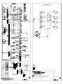
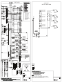
USER INTERFACE BOARD (UIB)

ATTENTION:
DÉBRANCHEZ L'APPAREIL AVANT DE PROCÉDER À LA RÉPARATION.
IDENTIFIEZ TOUS LES FILS AVANT DE LES DÉBRANCHER LORSQUE VOUS PROCÉDEZ À UNE RÉPARATION.
UNE ERREUR DE FILAGE PEUT CAUSER UN FONCTIONNEMENT INADÉQUAT ET/OU UNE SITUATION DANGEREUSE.
VÉRIFIEZ QUE L'APPAREIL FONCTIONNE CORRECTEMENT APRÈS LA RÉPARATION.
TRANSFORMATEUR
CONNECTEUR
RIGHT REAR IGNITER SWITCH
INTERRUPTEUR D'ALLUMAGE
DU BRÛLEUR ARRIÈRE DROITE
RIGHT FRONT IGNITER SWITCH
INTERRUPTEUR D'ALLUMAGE
DU BRÛLEUR AVANT DROITE
LEFT FRONT IGNITER SWITCH
INTERRUPTEUR D'ALLUMAGE
DU BRÛLEUR AVANT GAUCHE
LEFT REAR IGNITER SWITCH
INTERRUPTEUR D'ALLUMAGE
DU BRÛLEUR ARRIÈRE GAUCHE
IGNITER MODULE BOARD
PANNEAU DU MODULE D'ALLUMAGE
TOP BURNER
BRÛLEUR DE SURFACE
TOP BURNER
BRÛLEUR DE SURFACE
TOP BURNER
BRÛLEUR DE SURFACE
TOP BURNER
BRÛLEUR DE SURFACE
COOKTOP CIRCUIT
CIRCUIT DE LA TABLE DE CUISSON
IN/ENTRÉEOUT/SORTIE

p/n 807880711 FR (Rev A 16/03)
FEUILLE DE DONNÉES D’ENTRETIEN
Cuisinières encastrables à alimentation mixte munis d’une commande de four électronique
AVIS: Cette feuille de données d’entretien est destinée aux personnes ayant reçu une
formation en électricité et en mécanique, et qui possèdent un niveau de connaissance jugé
acceptable dans l’industrie de réparation des appareils électroménagers. Le fabricant ne peut
être tenu responsable, ni n’assumer aucune responsabilité, pour toute blessure ou dommage
de quelque nature que ce soit pouvant résulter de l’utilisation de cette feuille de données.
NOTE: Cette unité comprend une commande électronique du four. Cette commande de four
n’est pas réparable sur place.
PRATIQUES D’ENTRETIEN SÉCURITAIRES
Pour éviter tout risque de blessure et/ou dommage matériel, il est important que des
pratiques d’entretien sécuritaires soient suivies. Voici quelques exemples de pratiques
sécuritaires.
1. N’essayez jamais de réparer un appareil si vous ne croyez pas avoir les compétences
nécessaires pour le faire de manière satisfaisante et sécuritaire.
2. Avant de procéder au service d’entretien ou de déplacer tout appareil ménager, débran-
chez le cordon d’alimentation de la prise électrique, réglez le disjoncteur de circuit à
OFF, ou enlevez le fusible et fermez le robinet d’alimentation en gaz..
3. N’entravez jamais l’installation adéquate de tout dispositif de sécurité.
4. Utilesez que les pièces de remplacement énumérées dans le catalogue pour cet ap-
pareil. La moindre substituion risque de ne pas être conforme aux normes de sécurité
établies pour les appareils électroménagers.
5. Mise à la terre: La couleur de codage standard des conducteurs de mise à la terre
de sécurité est verte ou verte à barres jaunes. Les conducteurs de mise à la terre
ne doivent pas être utilisés comme conducteurs de courant. Il est d’une importance
capitale que le technicien d’entretien complète toutes les mises à la terre de sécurité
avant de terminer le service. Si cette recommandation n’est pas suivie à la lettre, il en
résultera des risques pour les personnes et les biens.
6. Avant de retourner le produit au service de réparation ou d’entretien, assurez-vous que:
• Toutes les connexions électriques sont correctes et sécuritaires.
• Tous les conducteurs électriques sont correctement préparés et placez de façon
sécuritaire à l’abri des bords tranchants, des composants à température élevée,
et des parties mobiles.
• Toutes les bornes électriques, connecteurs, réchauffeurs, etc. dénudés sont
espacés convenablement loin de toute pièce en métal et des panneaux.
• Toutes les mises à la terre de sécurité (interne et externe) sont correctement et
assemblées de façon sécuritaire.
• Tous les panneaux sont correctement et fermement remontés.
CALIBRATION DU FOUR
Réglez le point de consigne pour une cuisson traditionnelle à 350°F (177°C). Laisser le four
préchauffer à la température réglée. Mesurez la température moyenne du four après un mini-
mum de 5 cycles. Appuyez sur CANCEL pour arrêter ou annuler la cuisson en tout temps.
Ajustement de la température du four
1. Appuyez sur USER PREF jusqu’à ce que vous arriviez à la page UPO (four du haut).
2. Pour sélectionner le four que vous voulez ajuster, appuyez sur USER PREF encore une
fois pour changer à UPO dans l’écran du four du bas.
3. Entrez la température désirée en appuyant sur les touches + hi ou - lo. La température
peut seulement être ajustée de ± 35°F.
4. Appuyez sur START pour accepter les changements et retourner au menu des préférenc-
es.
Note: Modierlacalibrationaffectetouslesmodesdecuissonmaispaslesmodesdenettoy-
age et de grillage.
2-VITESSE VENTILATEUR RAFRAÎCHISSANT
Les contrôleurs de four électronique dirige vitesse de le ventilateur rafraîchissant. Le ventilateur
rafraîchissant activer à basse vitesse vitesse pendant une cuisson fonction, et il reste allumé
jusqu’à ce que du four refroidir. Le haut débit activer pendant grillage (avec la porte ouverte) et
pendant clean cycles seul quand la température est plus que approximativement 575ºF/302ºC.
MATRICE D’ANALYSE DU CIRCUIT
Sur le Panneau Relais Sur le Panneau TRIAC Sur le Panneau D’Alimentation
ÉLÉMENTS
Moteur
de porte
J3-5
Vent de
refroid
basse
J3-7
Vent de
refroid
haute
J3-8
Interr de porte
P10-3
Echec du
sonde des
grilles
P10-2
Cuisson
P9
Gril
P7
Conv.
P11
Vent. Conv.
P2-7
Lampe du
four
P2-1
Cuisson X X X* X X X*
Maintien chaud X X
Gril X X X
Cuisson conv. X X X X X X**
Rôtissage conv X X X X X X
Grillage conv. X X X X
Nettoyage X X X X
Verrouillage X
Verrouillé
Deverrouillage X
Déverrouillé
Lampe X
Porte ouverte X
Porte fermeé X
Pâte de pain X X
Echec du sonde des grilles X
Le relais sera en opération dans ces conditions
seulement
*L’élément de convection ainsi que le ventilateur sont en fonction pour la première
élévation de la température
DESCRIPTION DES CODES D’ERREUR DE LA COMMANDE DE FOUR
Note: “F1X” indique des erreurs internes de la commande du four; “F3X”, un problème avec la sonde du four et “F9x”, un problème avec le moteur verrou.
Code d erreur/État/Cause Action corrective suggérée
F10 La commande de four a décelé une condition
d’emballement possible. La commande
présente un relais en court-circuit, (RTD)
mauvais fonctionnement de la sonde.
VériezlasondeRTDetremplacez-lasinécessaire.Silefoursurchauffe,coupezlecourant.S’ilcontinuedesurchaufferunefoisle
courantrétabli,remplacezlepanneauderelaiset/oulepanneaud’afchage.
F11 Touches en court-circuit: si une touche a été
détectée comme enfoncée durant une longue
période de temps on la considère comme court-
circuitée et une alarme termine toute activité
1) Appuyez sur une touche pour effacer le code d’erreur.
2) Si le code réapparaît, remplacez le panneau de commande (clavier).
3)Sileproblèmepersiste,remplacezlepanneaud’afchage.
F13 La mémoire interne du contrôle est
corrompue.
1) Appuyez sur une touche pour effacer le code d’erreur.
2) Débranchez l’appareil, attendez 30 secondes et rebranchez l’appareil. Si le problème réapparaît lors du branchement, changez
lepanneaud’afchage.
F14 Câble du clavier mal connecté 1)Vériezlesconnexionsentrelepanneaud’afchageetleclavier(2câblesruban).Assurez-vousquelescâblessontbienconnectés
à chaque extrémité.
2) Si les câbles sont intacts, remplacez le clavier.
3)Sileproblèmepersiste,remplacezlepanneaud’afchage.
F15 Problèmeavecl’autovéricationducontrôleur 1) Un code F15 de la commande du four peut indiquer que la commande ne reçoit pas le signal de synchronisation de la plaque re-
lais. Une façon facile de déterminer cela est de débrancher l’appareil, rebrancher-le et démarrer un chronomètre de 1 minute avant
queleF15s’afche.Silaminuteriefonctionnenormalement,lasynchronisationaétéfaitecorrectement.Si1:00demeureafché
etquelecompteàreboursnedémarrepas,lasynchronisationaéchoué.Silasynchronisationaéchoué,vériezenpremiersi
laplaquerelaisreçoit120Vcorrectement(J4tiges1et3).parlasuite,vériezlelageentreleconnecteurJ2delaplaquerelais
etleconnecteurP16delacommandedufour.SilecourantACetlelagesontcorrectsetqueleproblèmeestencoreprésent,
remplacez la plaque relais. Si le problème persiste, remplacez la commande de four.
2)LecodeF15peutêtrecauséparundéfautdelacommandedufour.Silesignaldesynchronisationaétévériéettestébon,
remplacez la commande du four.
F20 Commande du four a détecté un problème
de communication avec les contrôleurs
d’éléments (ESEC)
1)Est-cequelaplaquedel’interfaceusagerESECfonctionne(est-cequelesécransafchentquelquechose?)Sinon,c’est
pourcelaquelacommandenepeutcommuniqueravec(ESECn’estpassoustension).Vérierlavoltage120VACàl’entréede
la plaque d’alimentation de l’ESEC située sur le devant de la console (connecteur P1) et le bas voltage provenant de la plaque
d’alimentation (connecteur P2) à l’interface usager du ESEC (connecteur P7).
2)VérierlesconnexionsentreleconnecteurP2delacommandedufouretP9del’interfaceusagerduESEC.Ceciestleliende
communication.Vériers’ilyaducourant.Référerauschémadecâblage.
3) Si toutes les étapes précédentes n’ont pas réglées le problème, remplacez l’interface usager du ESEC.
4) Si le problème persiste toujours, remplacez la commande du four.
F23 Le contrôleur a manqué sa communication
avec le panneau du ventilateur de convection
et des lumières.
1)VériezlelageentreP2surlepanneaud’afchageetP2surlepanneauduventilateurdeconvectionetlumières.
2)Sileslssontbons,remplacezlepanneauduventilateur.
3)Sileproblèmepersiste,remplacezlepanneaud’afchage.
F30:Problèmeaveclelagedesonde/lageouvert
(F30)ouNote:Lacommandedefourafchera
initialementlecode“F10”,celasigniequ’ildécèle
l’existence d’une condition d’emballement.
1)Vériezlelageducircuitdelasonde,ilestpeut-êtreouvertoucoupé.
2)VériezlarésistanceRTDàlatempératuredelapièce(comparezlesdonnéesautableau).Sicelle-cineconcordepas,remplacez
la sonde (RTD).
3) Laissez refroidir le four et redémarrez la fonction.
4)Sileproblèmepersiste,remplacezlepanneaud’afchage.
F31Court-circuit(F31)RTDproblèmesonde/lage.
Note:SiF30ouF31s’afchelorsquelefourestactif
ou lorsqu’il est en train d’entrer dans un mode actif.
F43 La vitesse du ventilateur de refroidissement,
lue par l’entrée du tachymètre du conseil
EOC-afchage,estanormalementtroplent.
1) Déterminez d’abord si le problème semble être causé par un ventilateur de refroidissement ne tourne pas ou tourne lentement ou
parunproblèmeavecladétectiondelavitesseduventilateur.Démarrerunecuissonetvérieraucoursdes15premièressecondes
si le ventilateur tourne (doit se sentir l’air se écoulant à travers l’évent dessus de la porte du four supérieur).
2)Sileventilateurnesemblepasêtredetourneroudetournerlentementle120VACvérierauniveauduventilateur.Si120VACest
présent au niveau du moteur de ventilateur, mais le ventilateur ne tourne pas remplacer le moteur du ventilateur. Si 120VAC ne est
pasprésentsurlemoteurduventilateurquandunCuireestdémarrévérierlaconnexionàlacartederelais(J3broche7)etneutre:
ilest120VACsurlabrocheJ37?Est-ilatteindrelemoteurduventilateur?Estl’autrebornedumoteurduventilateurconnectéà
Neutre?Sileharnaisoucartederelaissontdéfectueuxremplacer.
3)Sileventilateursembleêtrenormalementtourner,maisuncoded’erreurdeF43estgénérée,celasigniequ’ilyaunproblèmeavec
la lecture du capteur de vitesse du ventilateur. Assurez-vous que la connexion du capteur de vitesse du ventilateur est correctement
établie(cf.schémadecâblage),entrelecapteursurleventilateuretletableaud’afchageEOC.
4)Auxnsdedépannage,ilestpossibled’entrerdansunmodedetestquiindiqueraàl’écranlalecturedelavitesseduventilateur
en RPM: pour entrer dans le mode de test, la mise sous tension de l’appareil et à moins de 30 secondes, appuyez et maintenez le
four supérieur cuisson et de gril touches pour 3 secondes (jusqu’à ce que vous voyez tous les segments de l’écran allumé). Une fois
danslemodedetest,appuyezsurlatoucheLumièrefoursupérieurafcheraunefoislavitesseduventilateurdansRPM.Enmode
normal, le client d’erreur F43 est générée pour une vitesse du ventilateur en dessous d’environ 700 tours par minute.
F44 La vitesse du ventilateur de refroidissement,
lue par l’entrée du tachymètre du tableau
d’afchageEOC,estanormalementtrop
rapide.
1)Inspectezleventilateurderefroidissement.Ilnesemblesetournernormalement(uxd’air,bruit)?Vériezlapaledeventilateur
est bien assemblé.
2)Vériezqueriennebloqueleuxd’airduventilateur(quipourraitfairetournerleventilateurplusrapide).
3)Vériezlatension120VACsurleventilateur.Unetensionsupérieureà120VAC+10%pourraitfaireallertropvite.
4) Assurez-vous que la connexion du capteur de vitesse du ventilateur est correctement établie (cf. schéma de câblage), entre le
capteursurleventilateuretletableaud’afchageEOC.
5)Auxnsdedépannage,ilestpossibled’entrerdansunmodedetestquiindiqueraàl’écranlalecturedelavitesseduventilateur
en RPM: pour entrer dans le mode de test, la mise sous tension de l’appareil et à moins de 30 secondes, appuyez et maintenez le
four supérieur cuisson et de gril touches pour 3 secondes (jusqu’à ce que vous voyez tous les segments de l’écran allumé). Une fois
danslemodedetest,appuyezsurlatoucheLumièrefoursupérieurafcheraunefoislavitesseduventilateurdansRPM.Enmode
client normale l’erreur F44 est généré pour une vitesse de ventilateur au-dessus d’environ 2500 RPM.
6)Sileproblèmepersiste,remplacerleventilateur+capteurassemblageetletableaud’afchageEOC.
F90 F90 Système de verrouillage de porte
défectueux
1) Appuyez sur une touche pour effacer le code d’erreur.
2) Si cette étape n’élimine pas le problème, coupez le courant pendant 30 secondes et redémarrez l’appareil.
3)Vériezlelagedumoteurverrou,del’interrupteurverrouetlecircuitdel’interrupteurdelaporte.
4) Débranchez le moteur verrou, appliquez du courant (L1) directement au moteur verrou, si le moteur ne fonctionne pas, remplacez
l’assemblage.
5)Vériezsil’interrupteurverrouAfonctionneadéquatement(Est-cequ’ilpermetd’ouvriretdefermer,vériezavecunohmmètre).
Lemoteurverroudoit êtreréactivételqu’indiqué àl’étapeprécédenteanquel’interrupteurs’ouvreetseferme.Sil’interrupteur
verrou est défectueux, remplacez-le.
6) Si toutes les étapes mentionnées ci haut échouent, remplacez le panneau de relais ou le panneau électronique analogique dans
le cas ou le moteur verrou ne tourne pas.
7) Si toutes les étapes mentionnées ci haut échouent, remplacez le panneau électronique analogique dans le cas où le moteur verrou
tourne trop faiblement.
IMPORTANT
N’ENLEVEZ P
AS CE SAC OU NE
DÉTR
UISEZ P
AS SON CONTENU
CONTIENT LES SCHÉMAS DE CÂBLAGE ET
LES INFORMATIONS DE RÉPARATION
REMETTRE LE CONTENU
DANS LE SAC
ANALYSE
matrice
inférieure
FOUR
Sur la carte de relais
ÉLÉMENTS
DLB L2
out (P2)
cuire (P10)
cuire X X
Garder au
chaud
X X

P8 P10P12 P2 P4 P18
1
1
1
1
1
P7
P16
P15
P19
P13
P1P17P3P11
P9
J2 DC POWER
CONNECTS TO CONTROL P16
GROUND/TERRE
VLED (~+7 VDC)
VUR (~+15 VDC)
ZERO CROSS
J6 CONTROLS FAN,
NIGHT LIGHT, AUX
OUTPUT; CONNECTS
TO CONTROL P13
J5 - HEAT CONTROL OVEN
CONNECTS TO CONTROL P9
NEUTRAL/NEUTRE
L1
1
1
1
J4
J3
NEUTRAL/NEUTRE
L1
MDL/MOTEUR VERROU DE LA PORTE
COOLING FAN - LOW/VENT REFROID - BASSE
COOLING FAN - HIGH/VENT REFROID - HAUTE
BROIL
BAKE
CONVECTION ELEMENT/ÉLÉMENT DE CONVECTION
WARMER DRAWER ELEMENT/ÉLÉMENT DU TIROIR RÉCHAUD
GRIL
CUISSON
BAKE IGNITER/ALLUMEUR DU FOUR
BROIL IGNITER/ALLUMEUR DU GRIL
J2 DC ALIMENTATION
CONNECTE AU FOUR COMMANDE P16
J6 CONTRÔLE DU
VENTILATEUR, LUMIÈRE
DE NUIT, SORTIE AUX;
RELIÉ À UN CONTRÔLE P13
J5 - CONTRÔLE DE LA CHALEUR FOUR
CONNECTE AU FOUR COMMANDER P9
J5
J2
J6
P18 MEAT PROBE
P9 OUT
CONNECTS
TO J5
P6 PROGRAMMING HEADER
P1 TEMP PROBE
P3 TOUCH
KEY INPUTS
P16 POWER IN CONNECTS TO J2
P8 BACKLIGHT POWER CONNECTS TO POWER SUPPLY
P2 LIN COMM 1
CONNECTS TO TRIAC
P13 AUX OUT
CONNECTS TO J6
P10 SWITCH 1 OUT
1
MDL/MOTEUR VERROU DE LA PORTE
RACK SENSOR DEFEAT/ECHEC DU SONDE DES GRILLES
DOOR SWITCH/INTERRUPTEUR DE PORTE
COMMON/COMMUNE
P20 LOWER OVEN TEMP PROBE
LOW LIMIT THERMSTAT/THERMOSTAT LIMITE INFÉRIEURE
P18 SONDE À VIANDE
P9 SORTIE SE
CONNECTE AU
J5
P6 TÊTE DE PROGRAMMATION
P1 SONDE À TEMPÉRATURE
P3 EFFLEURER LA
TOUCHE ENTRÉES
P16 ALIMENTATION ENTRÉE CONNECTE AU J2
P8 PUISSANCE RÉTROÉCLAIRAGE SE CONNECTE AU SOURCE DE COURANT
P2 LIN COMM 1
SE CONNECTE AU TRIAC
P10 INTERRUPTEUR 1 SORTIE
P20 FOUR INFÉRIEUR SONDE À
TEMPÉRATURE
RELAY BOARD/PANNEAU DE RELAIS
OVEN CONTROL/ COMMANDE DU FOUR
Résistance (ohms)
1 000 ± 4,0
1 091 ± 5,3
1 453 ± 8,9
1 654 ± 10,8
1 852 ± 13,5
2 047 ± 15,8
2 237 ± 18,5
2 697 ± 24,4
Circuit ouvert/résistance infinie
ÉCHELLE DU DÉTECTEUR DE TEMPÉRATURE
À RÉSISTANCE
Température °F (°C)
32 ± 1,9 (0 ± 1,0)
75 ± 2,5 (24 ± 1,3)
250 ± 4,4 (121 ± 2,4)
350 ± 5,4 (177 ± 3,0)
450 ± 6,9 (232 ± 3,8)
550 ± 8,2 (288 ± 4,5)
650 ± 9,6 (343 ± 5,3)
900 ± 13,6 (482 ±7,5)
Circuit de la sonde mise à la
terre à la caisse
TABLEAU DE TEMPÉRATURE DE LA SONDE
vs SA RÉSISTANCE
Temperature Résistance
77 °F / 25°C 50.020Kohm+/-6%
122 °F / 50°C 18.020Kohm+/-5%
176 °F / 80°C 6.290Kohm+/-5%
212 °F / 100°C 3.400Kohm+/-5%

P2
P6P1
P6 PROGRAMMING
HEADER
1
OVEN LAMP/LAMPE DU FOUR
CONV FAN/VENT CONV
NEUTRAL/NEUTRE
L1
P1 CONNECTS TO
CONTROL P2
P6 TÊTE DE
PROGRAMMATION
P1 CONNECTE AU
FOUR COMMANDER P2
TRIAC BOARDUSER INTERFACE BOARD (UIB)/ PLAQUETTE D’INTERFACE DE UTILISATEUR (UIB)
J2 J4 P9
J3
P6P5
P7 CONNECTS TO
POWER SUPPLY
P3
P10
P9 CONNECTS TO
CONTROL P2 AND TRIAC
P7 SE CONNECTE
À L'ALIMENTATION
P9 SE CONNECTE À COMMANDE
DU FOUR P2 ET TRIAC
IMPORTANT
N’ENLEVEZ P
AS CE SAC OU NE
DÉTR
UISEZ P
AS SON CONTENU
CONTIENT LES SCHÉMAS DE CÂBLAGE ET
LES INFORMATIONS DE RÉPARATION
REMETTRE LE CONTENU
DANS LE SAC
p/n 807880711 FR (Rev A 16/03)

ATTENTION:
DÉBRANCHEZ L'APPAREIL AVANT DE PROCÉDER À LA RÉPARATION.
IDENTIFIEZ TOUS LES FILS AVANT DE LES DÉBRANCHER LORSQUE VOUS PROCÉDEZ À UNE RÉPARATION.
UNE ERREUR DE FILAGE PEUT CAUSER UN FONCTIONNEMENT INADÉQUAT ET/OU UNE SITUATION DANGEREUSE.
VÉRIFIEZ QUE L'APPAREIL FONCTIONNE CORRECTEMENT APRÈS LA RÉPARATION.
TRANSFORMATEUR
CONNECTEUR
RIGHT REAR IGNITER SWITCH
INTERRUPTEUR D'ALLUMAGE
DU BRÛLEUR ARRIÈRE DROITE
RIGHT FRONT IGNITER SWITCH
INTERRUPTEUR D'ALLUMAGE
DU BRÛLEUR AVANT DROITE
LEFT FRONT IGNITER SWITCH
INTERRUPTEUR D'ALLUMAGE
DU BRÛLEUR AVANT GAUCHE
LEFT REAR IGNITER SWITCH
INTERRUPTEUR D'ALLUMAGE
DU BRÛLEUR ARRIÈRE GAUCHE
IGNITER MODULE BOARD
PANNEAU DU MODULE D'ALLUMAGE
TOP BURNER
BRÛLEUR DE SURFACE
TOP BURNER
BRÛLEUR DE SURFACE
TOP BURNER
BRÛLEUR DE SURFACE
TOP BURNER
BRÛLEUR DE SURFACE
COOKTOP CIRCUIT
CIRCUIT DE LA TABLE DE CUISSON
IN/ENTRÉEOUT/SORTIE
INTERRUPTEUR
PORTE
MOTEUR VERROU
BASSE VITESSE
VENTILATEUR REFROIDISSEMENT
HAUTE VITESSE
FOUR DU BAS
ECHEC DU SONDE DES GRILLES
SONDE THERMIQUE DU HAUT
SONDE THERMIQUE DU BAS
TRANSFORMATEUR
SOURCE DE COURRANT
*CERTAINS MODELES
LEGEND/LEGENDE
CONNECTEUR
CAVITE
CONNECTEUR
VENTILATEUR REFROIDISSEMENT
DISJONCTEUR THERMIQUE
OVEN LAMP-HALOGEN
LAMPE DU FOUR-HALOGENE
CIRCUIT DU FOUR
PANNEAU DE RELAIS
LEGEND / LEGENDE
C.R. - CENTER REAR/CENTRE ARRIÈRE
R.F. - RIGHT FRONT/AVANT DROITE
R.R. - RIGHT REAR/ARRIÈRE DROITE
L.F. - LEFT FRONT/AVANT GAUCHE
L.R. - LEFT REAR/ARRIÈRE GAUCHE
LIM. - LIMITER/LIMITEUR
H.S. - HOT SURFACE/SURFACE CHAUDE
T.B. - TERMINAL BLOCK/BLOC DE BORNES
THM. - THERMAL CIRCUIT BREAKER/
DISJONCTEUR THERMIQUE
FN. - FAN/VENTILATEUR
-
 1
1
-
 2
2
-
 3
3
-
 4
4
-
 5
5
-
 6
6
-
 7
7
-
 8
8


Electrolux EW30DS80RS Information produit
- Taper
- Information produit
dans d''autres langues
Documents connexes
-
Electrolux EW30EW65PS Information produit
-
Electrolux EW30EW65PS English Wiring Diagram
-
Electrolux EW27EW55PS Wiring Diagram - English
-
-
-
Electrolux EI27EW35PS Information produit
-
-
Electrolux Icon E30MC75PPS Information produit
Autres documents
-
Frigidaire 801068 Information produit
-
Frigidaire FFGW2425QB Guide d'installation
-
Frigidaire FFGS3026TS Information produit
-
-
Frigidaire FGEW2765PF Information produit
-
-
-
-
Frigidaire FGEW3065PD Guide de démarrage rapide
-
Frigidaire FGIS3065PF Wiring Diagram (English)