Intellinet 24-Port Gigabit Ethernet PoE Web-Managed Switch with 4 SFP Combo Ports Quick Installation Guide
- Catégorie
- Commutateurs réseau
- Taper
- Quick Installation Guide
Ce manuel convient également à

24-PORT PoE+ WEB-
MANAGED GIGABIT
ETHERNET SWITCH
WITH 4 SFP PORTS
QUICK INSTALL GUIDE
MODEL 560900
INT-560900-QIG-ML1-0714-03
intellinet-network.com
Important: Read before use. • Importante: Leer antes de usar.

2
ENGLISH
PoE+ Web-Managed Gigabit Ethernet Switch English
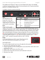
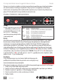
LED Status Operation
Power On Power on
Off Check the AC connection; turn the power on
PoE On Port is linked to a PSE/PoE device
Off No PSE/PoE device is linked
Link/Act On Valid port connection
& SFP Blinking Valid port connection; data transmitted/received
Off No link established
ON
OFF
This guide presents the basic steps to set up and operate this device. For detailed
instructions and specifications, refer to the user manual on the CD enclosed with this
product or at intellinet-network.com.
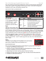
CONNECTIONS & INDICATORS
LEDs
The LED indicators (A) —
Power, PoE (1-24), Link/
Activity (1-24), SFP (F1-4) —
make it easier to monitor the
switch and its connections.
Ports
All ports on the switch
support Auto-MDI/MDI-X functionality, so crossover cables and uplink ports are not
needed for connections to PCs, routers, other switches, etc. Cat5/5e/6 UTP/STP cables
provide optimal performance; if a status LED doesn’t indicate a link or activity, check
the corresponding device for proper setup and operation. The recessed Reset button
(B) can be pressed (using a pin or similar pointed object) to reset the switch if it isn’t
responding. NOTE: SFP ports F1-4 (C) share connections with RJ45 ports 1-4 (D). If
ports 1 and F1 are both connected to devices, only F1 will link.
Power
Use the included power cord to connect the device (next to
the On/Off switch on the rear panel) to an AC outlet.
RACKMOUNT
The switch includes brackets and screws for optional rack mounting.
1. Disconnect any cables from the switch.
2. Position a bracket over the mounting holes on one side of the switch and secure it
in place with screws.
3. Repeat Step 2 on the other side of the switch.
4. Position the switch in the rack and screw the brackets to the rack.
5. Reconnect any cables.
1 3 5 7 9 11 13 15 17 19 21 23
2 4 6 8 10 12 14 16 18 20 22 24
Power
Reset
PoE
PoE
LINK/ACT
LINK/ACT
F1
F4
F3
F2
Combo
A
B
C
D

DEUTSCH
3
PoE+ Web-Managed Gigabit Ethernet Switch Deutsch
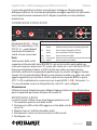
Diese Kurzanleitung zeigt die grundlegenden Schritte zur Einrichtung und Inbetrieb-
nahme dieses Geräts. Für genauere Anweisungen nutzen Sie bitte das beiliegende
Handbuch auf CD oder auf intellinet-network.com.
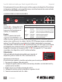
ANSCHLÜSSE & ANZEIGEN
LED-Anzeigen
Die LEDs (A) — Strom, PoE
(1-24), Verbindung/Aktivität
(1-24), SFP (F1-4) — verein-
fachen das Ablesen der
Funktionen und Anschlüsse.
Ports
Alle Ports unterstützen Auto-
MDI/MDI-X Funktionalität, daher werden Crosskabel und Uplink-Ports für Verbindungen
zu PCs, Routern, anderen Switchen, etc. nicht benötigt. Cat5/5e- UTP/STP-Kabel bieten
die beste Performance. Wenn eine LED keine Verbindung/Aktivität anzeigt, überprüfen
Sie das verbundene Gerät. Der Reset-Knopf (B) kann (mit einer Büroklammer oder
ähnlichem) gedrückt werden, um den Switch zurückzusetzen, falls er nicht mehr
reagiert. HINWEIS: Die SFP-Ports F1-4 (C) und die RJ45-Ports 1-4 (D) sind Kombo-Ports,
d. h. wenn an die Ports 1 und F1 Geräte angeschlossen sind, ist nur die Verbindung
über F1 aktiv.
Strom
Schließen Sie das beiliegende Stromkabel an das Gerät (neben
dem An/Aus-Schalter) und an eine Steckdose an. V
RACKMONTAGE
Diesem Switch liegen Haltewinkel und Schrauben für optionale Rackmontage bei.
1. Trennen Sie alle Kabel von dem Switch.
2. Platzieren Sie einen Haltewinkel über den Montagelöchern auf einer Seite des
Switches und fixieren Sie ihn mit Schrauben.
3. Wiederholen Sie Schritt 2 auf der anderen Seite des Switches.
4. Platzieren Sie den Switch in dem Rack und schrauben Sie die Haltewinkel fest.
5. Schließen Sie alle Kabel wieder an.
LED Status Operation
Power An Gerät wird mit Strom versorgt
Aus Stromanschluss prüfen/Gerät einschalten
PoE An Port ist mit PSE/PoE-Gerät verbunden
Aus Kein PSE/PoE-Gerät angeschlossen
Link/Act An Verbindung ist hergestellt
& SFP Blinkend Verbindung ist hergestellt; Datenübertragung
Aus Verbindung ist nicht hergestellt
ON
OFF
1 3 5 7 9 11 13 15 17 19 21 23
2 4 6 8 10 12 14 16 18 20 22 24
Power
Reset
PoE
PoE
LINK/ACT
LINK/ACT
F1
F4
F3
F2
Combo
A
B
C
D

4
ESPAÑOL
Switch Administrable por Web Gigabit Ethernet Español
Esta guía presenta los pasos básicos para instalar y operar este dispositivo. Para obtener
instrucciones detalladas y más especificaciones, consulte el manual de usuario incluido
en el CD o visite intellinet-network.com
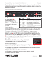
CONEXIONES E INDICADORES
LEDs
Los LEDs (A) — Power, PoE (1-24),
Link/Activity (1-24), SFP (F1-4) —
hacen mas facil monitorear el
switch y sus conexiones.
Puertos
Todos los puertos del switch
soportan Auto-MDI/MDI-X , los
cables crossover y puertos de enlace no son necesarios para las conexiones para PCs,
routers, otros switches, etc. los cables Cat5/5e UTP/STP proporcionan un redimiento
optimo; Si un LED no indica conectividad ó actividad, compruebe las conexiones
sean adecuadas. El botón reinicio (B) se puede presionar (con una aguja u otro objeto
puntiagudo) para resetear el switch si no responde. NOTA: Los puertos SFP F1-4 (C)
comparten conexión con los puertos RJ45 1-4 (D). Si los puertos 1 y F1 son ambos
conectados a los dispositivos, solo F1 realizara el enlace.
Alimentación
Utilice el cable de alimentación incluido para conectar el
dispositivo (junto al switch On /Off) a una toma de CA.
MONTAJE EN RACK
El switch incluye soportes y tornillos opcionales para el montaje en el Rack.
1. Desconecte cualquier cable del switch.
2. Coloque el soporte sobre los orificios de montaje, ubicados a un lado del switch y
sujételo con los tornillos.
3. Repita el paso 2 en el lado contrario del switch.
4. Coloque el switch en el rack y atornille los soportes al rack.
5. Conecte nuevamente todos los cables.
LED Estado Operación
Power Encendido Encendido
Apagado Revise la conexión AC; encienda de nuevo
PoE Encendido Puerto vinculado a un dispositivo PSE/PoE
Apagado No hay un dispositivo PSE/PoE conectado
Link/Act Encendido Valide el puerto de conexión
& SFP Parpadeo Datos trasmitidos/recibidos
Apagado No hay comunicación
ON
OFF
1 3 5 7 9 11 13 15 17 19 21 23
2 4 6 8 10 12 14 16 18 20 22 24
Power
Reset
PoE
PoE
LINK/ACT
LINK/ACT
F1
F4
F3
F2
Combo
A
B
C
D

FRAN
Ç
AIS
5
Commutateur PoE+ Gigabit Web Ethernet Français
Ce guide décrit les bases pour configurer et opérer cet appareil. Pour des instructions
et spécifications détailées, veuillez lire le manuel de l’utilisateur sur le CD inclus ou sur
intellinet-network.com
CONNEXIONS & INDICATEURS
Les DEL
Les voyants d’état (A) —
Alimentation, PoE (1-24),
Connexion/Activité (1-24),
SFP (F1-4) — simplifient lire les
fonctions et les connexions.
Les ports
Tous les ports de ce
commutateur prennent en charge la fonctionnalité Auto-MDI/MDI-X, donc des câbles
croisés et des liaisons montantes ne sont pas nécessaires pour des connections aux
PC, routeurs, etc. Des câbles Cat5/5e UTP/STP garantissent des performances
optimales; si un DEL n’indique pas d’activité, vérifiez l’appareil correspondant. Le
bouton de reset (B) peut être appuyé (avec un trombone ou un objet similaire) si le
commutateur ne réagit pas. REMARQUE: Les ports SFP F1-F4 (C) et les ports RJ45 1-4
(D) sont des ports mixtes, cela veut dire si des appareils sont connectés aux ports 1 et
F1, seulement la connexion via F1 est active.
Alimentation
Connectez le cordon d’alimentation à l’appareil (à côté de
l’ interrupteur du réseau) et à une prise de courant.
MONTAGE EN RACK
Le commutateur inclut des équerres et vis pour un montage en rack optionnelle.
1. Déconnectez tous les cordons du commutateur.
2. Positionnez une équerre sur les trous de montage à un côté du commutateur et
sécurisez-la avec des vis.
3. Répétez l’étape 2 à l’autre côté du commutateur.
4. Positionnez le commutateur en rack et vissez les équerres au rack.
5. Reconnectez tous les cordons.
LED État Operation
Power Allumé Appareil est alimenté
Éteint Vérifiez l’alimentation/Allumez l’appareil
PoE Allumé Port est connecté à un appareil PSE/PoE
Éteint Port n’est connecté pas à un appareil PSE/PoE
Link/Act Allumé Connexion est établie
& SFP Clignotant Connexion est établie; données sont transmises
Éteint Connexion n’est pas établie
ON
OFF
1 3 5 7 9 11 13 15 17 19 21 23
2 4 6 8 10 12 14 16 18 20 22 24
Power
Reset
PoE
PoE
LINK/ACT
LINK/ACTF1
F4
F3
F2
Combo
A
B
C
D

6
POLSKI
Przełącznik Web-Smart Gigabit Ethernet PoE+ Polski
Dioda Status Objaśnienie
Power On (wł.) Urządzenie włączone
Off (wył.) Sprawdź, czy zasilanie jest podłączone; włącz urządzenie
PoE On (wł.) Port jest połączony z urządzeniem PoE
Off (wył.) Nie ma połączenia z urządzeniem PoE
Link/Act On (wł.) Prawidłowe podłączenie portu
& SFP
Migająca Prawidłowe podłączenie portu; transmisja/odbiór pakietów
Off (wył.) Nie nawiązano połączenia
Niniejsza instrukcja szybkiej instalacji przedstawia podstawowe kroki potrzebne
do uruchomienia i obsługi urządzenia. Aby uzyskać szczegółowe informacje
techniczne oraz podręcznik użytkownika zapoznaj się z zawartością dołączonej
płyty CD lub odwiedź stronę intellinet-network.com.
PANEL PRZEDNI URZĄDZENIA
Diody
Diody sygnalizacyjne LED
(A)
— dla funkcji zasilania, PoE
(1-24), link/aktywności (1-24),
SFP (F1-4) — ułatwiają
monitorowanie przełącznika
i jego połączeń.
Porty
Wszystkie porty przełącznika obsługują auto-krosowanie MDI/MDI-X, więc kabel
krosowany oraz port
uplink nie jest wymagany do połączenia z komputerami,
routerami, czy innymi przełącznikami.
Kable Cat5/5e/6 UTP/STP zapewniają
optymalną wydajność; jeśli diody statusu nie sygnalizują linku lub aktywności,
sprawdź podłączone urządzenie pod kątem
poprawności konfiguracji oraz jego
zasilania. Znajdujący się w zagłębieniu
przycisk Reset
(B)
należy wcisnąć cienkim
narzędziem, aby zresetować przełącznik.
UWAGA:
Porty SFP (F1-4)
(C)
dzielą łącza
z portami RJ45 1-4
(D)
. Jeśli oba porty 1 oraz F1 są podłączone do urządzeń, tylko
jeden z nich - F1 jest zlinkowany.
Zasilanie
Użyj znajdującego się w zestawie kabla zasilającego do
podłączenia przełącznika do gniazda sieci energetycznej.
MOCOWANIE RACKOWE
W zestawie znajdują się uchwyty oraz śrubki do opcjonalnego mocowania rackowego.
1. Odłącz wszystkie kable od przełącznika.
2. Umieść uchwyt na dziurach na bocznej części przełącznika i przykręć go śrubami.
3. Powtórz czynność z punktu nr 2 dla drugiego uchwytu.
4. Umieść przełącznik w racku i przykręć go śrubami.
5. Podłącz kable.
ON
OFF
1 3 5 7 9 11 13 15 17 19 21 23
2 4 6 8 10 12 14 16 18 20 22 24
Power
Reset
PoE
PoE
LINK/ACT
LINK/ACTF1
F4
F3
F2
Combo
A
B
C
D

ITALIANO
7
Gigabit PoE+ a Web Management Ethernet Switch Italiano
LED Stato Operazione
PWR Acceso Acceso
Spento Verificare la connessione AC; accendere l’apparecchio
PoE Acceso Porta collegata alla periferica PSE/PoE
Spento Nessuna periferica PSE/PoE è collegata
LNK/ Acceso Porta di connessione valida
ACT
Lampeggiante
Porta di connessione valida; trasmissione/ricevimento dati
& SFP
Spento Nessuna connessione stabilita
La presente guida fornisce le basi essenziali per il settaggio e il funzionamento
dell’apparecchiatura. Per istruzioni più dettagliate e maggiori specifiche, far riferimento
al manuale d’istruzioni contenuto nel CD allegato al prodotto o visitare intellinet-
network.com.
CONNESSIONI E INDICATORI
LEDs
Gli indicatori LED (A) — Power,
PoE
(1-24)
, Link/Activity
(1-24),
SFP (F1-4)
— permettono di
monitorare facilmente lo
switch e le sue connessioni.
Porte
Tutte le porte dello switch
supportano la funzionalità
Auto-MDI/MDI-X, così cavi incrociati e porte uplink non
sono necessarie per connessioni
a PC, router, altri switch, etc. I cavi Cat5/5e/6 UTP/STP
forniscono ottimali prestazioni; se il LED di stato non indica una connessione o
un’attività, verificare la corrispondente periferica per un corretto settaggio e funzion-
amento. Il tasto rientrante Reset
(B)
può essere premuto (usando uno spillo o un simile
oggetto appuntito) per resettare lo switch se questo non risponde. NOTA:
Le porte
SFP F1-4
(C)
condividono le connessioni con le porte RJ45 1-4
(D)
. Se le porte 1 e
F1 sono entrambe connesse alle periferiche, solo la F1 verrà collegata.
Alimentazione
Utilizzare il cavo di alimentazione per collegare l’apparecchiatura (vicino all’interruttore
posto sul pannello posteriore) alla presa di corrente AC.
MONTAGGIO A RACK
Lo switch include staffe e viti per il montaggio opzionale a rack.
1. Disconnettere qualsiasi cavo dallo switch.
2. Posizionare la staffa sui fori di fissaggio su un lato dello switch e assicurarla sul posto
con le viti.
3. Ripetere il passo 2 sull’altro lato dello switch.
4. Posizionare lo switch sul rack ed avvitare le staffe sul rack.
5. Recollegare i cavi.
ON
OFF
1 3 5 7 9 11 13 15 17 19 21 23
2 4 6 8 10 12 14 16 18 20 22 24
Power
Reset
PoE
PoE
LINK/ACT
LINK/ACTF1
F4
F3
F2
Combo
A
B
C
D

8
WASTE ELECTRICAL & ELECTRONIC EQUIPMENT
Disposal of Electric and Electronic Equipment
(applicable in the European Union and other European countries with separate collection systems)
ENGLISH
This symbol on the product or its packaging indicates that this product shall not be treated as household
waste. Instead, it should be taken to an applicable collection point for the recycling of electrical and
electronic equipment. By ensuring this product is disposed of correctly, you will help prevent
potential negative consequences to the environment and human health, which could otherwise
be caused by inappropriate waste handling of this product. If your equipment contains easily
removable batteries or accumulators, dispose of these separately according to your local
requirements. The recycling of materials will help to conserve natural resources. For more
detailed information about recycling of this product, contact your local city office, your household waste
disposal service or the shop where you purchased this product. In countries outside of the EU: If you wish
to discard this product, contact your local authorities and ask for the correct manner of disposal.
DEUTSCH
Dieses auf dem Produkt oder der Verpackung angebrachte Symbol zeigt an, dass dieses Produkt nicht mit
dem Hausmüll entsorgt werden darf. In Übereinstimmung mit der Richtlinie 2002/96/EG des Europäischen
Parlaments und des Rates über Elektro- und Elektronik-Altgeräte (WEEE) darf dieses Elektrogerät nicht
im normalen Hausmüll oder dem Gelben Sack entsorgt werden. Wenn Sie dieses Produkt entsorgen
möchten, bringen Sie es bitte zur Verkaufsstelle zurück oder zum Recycling-Sammelpunkt Ihrer Gemeinde.
ESPAÑOL
Este símbolo en el producto o su embalaje indica que el producto no debe tratarse como residuo doméstico.
De conformidad con la Directiva 2002/96/CE de la UE sobre residuos de aparatos eléctricos y electrónicos
(RAEE), este producto eléctrico no puede desecharse con el resto de residuos no clasificados. Deshágase
de este producto devolviéndolo a su punto de venta o a un punto de recolección municipal para su
reciclaje.
FRANÇAIS
Ce symbole sur Ie produit ou son emballage signifie que ce produit ne doit pas être traité comme un
déchet ménager. Conformément à la Directive 2002/96/EC sur les déchets d’équipements électriques
et électroniques (DEEE), ce produit électrique ne doit en aucun cas être mis au rebut sous forme de
déchet municipal non trié. Veuillez vous débarrasser de ce produit en Ie renvoyant à son point
de vente ou au point de ramassage local dans votre municipalité, à des fins de recyclage.
POLSKI
Jeśli na produkcie lub jego opakowaniu umieszczono ten symbol, wówczas w czasie utylizacji nie wolno
wyrzucać tego produktu wraz z odpadami komunalnymi. Zgodnie z Dyrektywą Nr 2002/96/WE w sprawie
zużytego sprzętu elektrycznego i elektronicznego (WEEE), niniejszego produktu elektrycznego nie wolno
usuwać jako nie posortowanego odpadu komunalnego. Prosimy o usuniecie niniejszego produktu
poprzez jego zwrot do punktu zakupu lub oddanie do miejscowego komunalnego punktu zbiórki
odpadów przeznaczonych do recyklingu.
ITALIANO
Questo simbolo sui prodotto o sulla relativa confezione indica che il prodotto non va trattato come un rifiuto
domestico. In ottemperanza alla Direttiva UE 2002/96/EC sui rifiuti di apparecchiature elettriche ed
elettroniche (RAEE), questa prodotto elettrico non deve essere smaltito come rifiuto municipale misto. Si
prega di smaltire il prodotto riportandolo al punto vendita o al punto di raccolta municipale locale per un
opportuno riciclaggio.

9
REGULATORY STATEMENTS
FCC Class A
This equipment has been tested and found to comply with the limits for a Class A digital device,
pursuant to Part 15 of the Federal Communications Commission (FCC) Rules. These limits are
designed to provide reasonable protection against harmful interference when the equipment
is operated in a commercial environment. This equipment generates, uses and can radiate radio
frequency energy, and if not installed and used in accordance with the instruction manual may
cause harmful interference to radio communications. Operation of this equipment in a residential
area is likely to cause harmful interference, in which case the user will be required to correct
the interference at his own expense. Any changes or modifications made to this equipment without
the approval of the manuafacturer could result in the product not meeting the Class A limits, in
which case the FCC could void the user’s authority to operate the equipment.
CE / R&TTE
ENGLISH
This device complies with the requirements of R&TTE Directive 1999/5/EC. The Declaration of
Conformity for this product is available at intellinet-network.com.
DEUTSCH
Dieses Gerät enspricht der Direktive R&TTE Direktive 1999/5/EC. Die Konformitätserklärung für dieses
Produkt finden Sie unter intellinet-network.com.
ESPAÑOL
Este dispositivo cumple con los requerimientos de la Directiva R&TTE 1999/5/EC. La declaración de
conformidad para este producto esta disponible en intellinet-network.com.
FRANÇAIS
Cet appareil satisfait aux exigences de la directive R&TTE 1999/5/CE. La Déclaration de Conformité
pour ce produit est disponible à l’adresset intellinet-network.com.
POLSKI
Urządzenie spełnia wymagania dyrektywy R&TTE 1999/5/EC. Deklaracja zgodności dostępna jest na
stronie internetowej producenta intellinet-network.com.
ITALIANO
Questo dispositivo è conforme alla Direttiva 1999/5/EC R&TTE. La dichiarazione di conformità per
questo prodotto è disponibile al intellinet-network.com.

10
WARRANTY INFORMATION
ENGLISH —
For warranty information, go to intellinet-network.com/warranty.
DEUTSCH —
Garantieinformationen finden Sie hier unter intellinet-network.com/warranty.
ESPAÑOL —
Si desea obtener información sobre la garantía, visite
intellinet-network.com/warranty.
FRANÇAIS —
Pour consulter les informations sur la garantie, rendezvous à l’adresse
intellinet-network.com/warranty.
POLSKI —
Informacje dotyczące gwarancji znajdują się na stronie intellinet-network.com/warranty.
ITALIANO —
Per informazioni sulla garanzia, accedere a intellinet-network.com/warranty.
EN MÉXICO: Póliza de Garantia Intellinet — Datos del importador y responsable ante el consumidor
IC Intracom México, S.A.P.I. de C.V. • Av. Interceptor Poniente # 73, Col. Parque Industrial La Joya, Cuautitlán
Izcalli, Estado de México, C.P. 54730, México. • Tel. (55)1500-4500
La presente garantía cubre este producto por 3 años contra cualquier defecto de fabricación en sus
materiales y mano de obra, bajo las siguientes condiciones:
1. Todos los productos a que se refiere esta garantía, ampara su cambio físico, sin ningún cargo para
el consumidor.
2. El comercializador no tiene talleres de servicio, debido a que los productos que se garantizan no
cuentan con reparaciones, ni refacciones, ya que su garantía es de cambio físico.
3. La garantía cubre exclusivamente aquellas partes, equipos o sub-ensambles que hayan sido instaladas
de fábrica y no incluye en ningún caso el equipo adicional o cualesquiera que hayan sido adicionados
al mismo por el usuario o distribuidor.
Para hacer efectiva esta garantía bastará con presentar el producto al distribuidor en el domicilio donde
fue adquirido o en el domicilio de IC Intracom México, S.A.P.I. de C.V., junto con los accesorios con-
tenidos en su empaque, acompañado de su póliza debidamente llenada y sellada por la casa vende-
dora (indispensable el sello y fecha de compra) donde lo adquirió, o bien, la factura o ticket de compra
original donde se mencione claramente el modelo, número de serie (cuando aplique) y fecha de
adquisición. Esta garantía no es válida en los siguientes casos: Si el producto se hubiese utilizado en
condiciones distintas a las normales; si el producto no ha sido operado conforme a los instructivos de
uso; o si el producto ha sido alterado o tratado de ser reparado por el consumidor o terceras personas.
All trademarks and trade names are the property of their respective owners.
Alle Marken und Markennamen sind Eigentum Ihrer jeweiligen Inhaber.
Todas las marcas y nombres comerciales son propiedad de sus respectivos dueños.
Toutes les marques et noms commerciaux sont la propriété de leurs propriétaires respectifs.
Wszystkie znaki towarowe i nazwy handlowe należą do ich właścicieli.
Tutti i marchi registrati e le dominazioni commerciali sono di proprietà dei loro rispettivi proprietari.
North & South America
IC Intracom Americas
550 Commerce Blvd.
Oldsmar, FL 34677
USA
Asia & Africa
IC Intracom Asia
4-F, No. 77, Sec. 1, Xintai 5th Rd.
Xizhi Dist., New Taipei City 221
Taiwan
Europe
IC Intracom Europe
Löhbacher Str. 7
D-58553 Halver
Germany


© IC Intracom. All rights reserved.
Intellinet is a trademark of IC Intracom, registered in the U.S. and other countries.
-
 1
1
-
 2
2
-
 3
3
-
 4
4
-
 5
5
-
 6
6
-
 7
7
-
 8
8
-
 9
9
-
 10
10
-
 11
11
-
 12
12


Intellinet 24-Port Gigabit Ethernet PoE Web-Managed Switch with 4 SFP Combo Ports Quick Installation Guide
- Catégorie
- Commutateurs réseau
- Taper
- Quick Installation Guide
- Ce manuel convient également à
dans d''autres langues
- italiano: Intellinet 24-Port Gigabit Ethernet PoE Web-Managed Switch with 4 SFP Combo Ports
- English: Intellinet 24-Port Gigabit Ethernet PoE Web-Managed Switch with 4 SFP Combo Ports
- español: Intellinet 24-Port Gigabit Ethernet PoE Web-Managed Switch with 4 SFP Combo Ports
- Deutsch: Intellinet 24-Port Gigabit Ethernet PoE Web-Managed Switch with 4 SFP Combo Ports
- polski: Intellinet 24-Port Gigabit Ethernet PoE Web-Managed Switch with 4 SFP Combo Ports
Documents connexes
-
Intellinet 560542 Quick Install Guide
-
Intellinet 560849 Manuel utilisateur
-
Intellinet 16-Port Gigabit Ethernet PoE Web-Managed Switch with 2 SFP Ports Quick Install Guide
-
Intellinet 16-Port Gigabit Ethernet PoE Web-Managed Switch with 2 SFP Ports Guide d'installation
-
Intellinet 560856 Quick Install Guide
-
Intellinet 560641 Quick Instruction Guide
-
Intellinet 5-Port Gigabit Ethernet PoE Switch Quick Instruction Guide
-
Intellinet 560764 Manuel utilisateur
-
-