Tetra Contour LED Signage Guide d'installation
- Taper
- Guide d'installation

Installation Guide
SIGN174 | GE2024-0587
GEXNBL-1, GEXNGL-1, GEXNYG-1, GEXNRC-1,
GEXNRD-1, GEXN65-1, GEXN32-1
2424
Volt
This device complies with part 15 of the FCC Rules. Operation is subject
to the following two conditions: (1) This device may not cause harmful
interference, and (2) this device must accept any interference received,
including interference that may cause undesired operation.
CAN ICES-005 (A) / NMB-005 (A)
Note: This equipment has been tested and found to comply with the
limits for a Class A digital device, pursuant to part 15 of the FCC Rules.
These limits are designed to provide reasonable protection against
harmful interference when the equipment is operated in a commercial
environment. This equipment generates, uses, and can radiate radio
frequency energy and, if not installed and used in accordance with
the instruction manual, may cause harmful interference to radio
communications. Operation of this equipment in a residential area
is likely to cause harmful interference in which case the user will be
required to correct the interference at his own expense.
Save These Instructions
Use only in the manner intended by the manufacturer.
If you have any questions, contact the manufacturer.
RETROFIT SIGN CONVERSION LED KIT FOR USE ONLY IN
ACCORDANCE WITH KIT INSTRUCTIONS.
KIT IS COMPLETE ONLY WHEN ALL PARTS REQUIRED BY
THE INSTRUCTIONS ARE PRESENT.
TROUSSE DE CONVERSION À DEL POUR LA
MODERNISATION DES ENSEIGNES
À UTILISER CONFORMÉMENT AU GUIDE D’INSTALLATION.
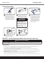
WARNING / AVERTISSEMENT
RISK OF ELECTRIC SHOCK
• Disconnect power at fuse box or circuit breaker before
servicing or installing product.
• Properly ground Tetra® power supply.
RISK OF FIRE
• Use only Tetra® supply wire to make connection from
Tetra® power supply to Tetra® LED strip.
• Use only approved wire for input/output connection.
Minimum size 18 AWG (0.82mm2)
• Follow all local codes.
• Waterproof wire connection for outdoor or wet
installations. See instructions for details.
• Do not stretch light engines.
• Inspect and replace the light engines if any tear or damage
affects their integrity.
• Avoid installation that leads to prolonged exposure to
standing water or ice.
RISK OF FIRE OR ELECTRIC SHOCK
• LED Retrofit Kit installation requires knowledge of
sign electrical systems. If not qualified, do not attempt
installation. Contact a qualified electrician.
• Install this kit only in host signs that have been identified in
the installation instructions and where the input rating of
the retrofit kit does not exceed the input rating of the sign.
• Installation of this LED retrofit kit may involve drilling or
punching of holes into the structure of the sign. Check
for enclosed wiring and components to avoid damage to
wiring and electrical parts.
• Do not make or alter any open holes in an enclosure of
wiring or electrical components during kit installation.
RISQUES DE CHOC ÉLECTRIQUE
• Coupez l’alimentation électrique à la boîte de fusibles ou au disjoncteur avant
l’entretien ou l’installation du produit.
• Assurez-vous de correctement mettre à terre l’alimentation électrique Tetra®.
RISQUES D’INCENDIE
• N’utilisez que le fil d’approvisionnement Tetra® pour faire la connexion entre
l’alimentation Tetra® et la bande DEL Tetra®.
• N’utilisez que des fils approuvés pour les entrées/sorties de connexion. Taille
minimum 18 AWG (0.82mm2).
• Respectez tous les codes locaux.
• Étanchéifier les connexions électriques effectuées à l’extérieur ou pour un
environnement exposé à l’eau. Voir les instructions d’installation pour plus de détails.
• Ne pas étirer les modules DEL Contour.
• Inspecter l’intégrité des modules DEL Contour et les remplacer s’ils sont déchirés
ou endommagés.
• Éviter les installations avec une exposition prolongée à l’eau stagnante ou à la glace.
RISQUE D’INCENDIE OU DE CHOC ÉLECTRIQUE
• L’installation de l’équipement de remplacement DEL exige Ia connaissance des
systèmes électriques pour enseignes. Si non qualifié, ne tentez pas d’installation.
Veuillez contacter un électricien qualifié
• Risque d’incendie ou de choc Électrique. Installez cet ensemble seulement dans des
enseignes hôtes qui ont été identifiés dans les instructions d’installation et dont la
capacité d’entrée de l’ensemble ne dépasse pas la capacité d’entrée de l’enseigne.
• L’installation de cet équipement de remplacement DEL peut impliquer le
perçage ou le poinçonnage de trous dans la structure du panneau Vérifiez le
câblage et les composants inclus pour éviter d’endommager le câblage et les
composants électriques.
• Ne pas faire ou modifier les trous ouverts dans une enceinte de câblage
ou de composants électriques pendant l’installation de cet équipement de
remplacement DEL.
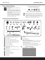
Contour
LED Lighting System
BEFORE YOU BEGIN
Read these instructions completely and carefully.

Installation Guide
2
Tetra® Contour
Components and Tools Required
Prepare Electrical Wiring
Electrical Requirements
• Light engines without light guide limited to indoor
dry locations.
• Light engines with light guide acceptable to use in
dry, damp or wet locations when installed correctly.
• The grounding and bonding of the LED Driver shall
be done in accordance with National Electric Code
(NEC) Article 600.
• Follow all National Electric Codes (NEC) and local codes.
• These products are only suitable for connection to a
circuit from a Class 2 power source. These products
have not been evaluated for use when connected to
a power source that does not comply with Class 2
voltage and energy limited supplies.
UL approved 18 AWG (0.82mm2) supply wire
Tetra® End Caps
Tetra® Contour Light Guide connector
Tetra® Contour Light Guide 90° inside corner
Tetra® Contour Light Guide 90° outside corner
Tetra® Contour Light Guide 90° planar corner
Tetra® mounting clips
Weather box GEXNWB2
22 AWG (0.33mm2) tie-wire
#6, #8 or #10 (M2, M3 or M4) self drilling pan
headed screws
#6 (M2) screws
UL approved 22-14 AWG (0.33-2.08mm2) twist-on
wire connectors
Volt power supply
Tetra® Contour Light Engine
Tetra® Contour Light Guide
Cordless drill
Tape measure
Screwdriver
Wire stripper/cutter
Electrical grade silicone
Examples of electrical grade silicone:
• Momentive RTV 6700 Series Silicone Rubber Adhesive Sealant
• Momentive White Blanc RTV 162 Silicone Rubber Adhesive
Sealant-Electrical Grade
• Dow Corning 3140 - Non-Corrosive Flowable (clear)
• Dow Corning 3145 - Non-Corrosive Nonflowable (clear or gray)
• Dow Corning RTV 748 Non-Corrosive Sealant-White
8 feet (2.44m)
Tc=85°C
8 feet (2.44m)
Cutting Resolution Table
Light Engine Color Cutting Resolution
Red 2.29 in. (58 mm)
Red-orange 2.29 in. (58 mm)
Amber 2.29 in. (58 mm)
Green 2.29 in. (58 mm)
Blue 2.29 in. (58 mm)
White 2.00 in. (51 mm)
Warm White 2.00 in. (51 mm)
1
1 2 3 4 5 6 7 8 9
2
3
4
5
6
7
8
9
10
10
11
11
12
13
14
15
16
17
17
18
18
19
19
20
20
21
12 13
14
15
16
This product is intended solely for sign use only.
Not intended for general lighting applications.
Conforms to the following standards:
Note: “CE” and “UKCA” applies to models GEXNRD-1,
GEXNBL-1, GEXNGL-1, GEXNYG-1, and GEXNRC-1 only.
Electrical products must not be thrown out with domestic
waste. They must be taken to a communal collecting point for
environmentally friendly disposal in accordance with local
regulations. Contact your local authorities or stockist for advice
on recycling. The packaging material is recyclable. Dispose of the
packaging in an environmentally friendly manner and make it
available for the recyclable material collection-service.

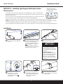
Installation Guide
3
Tetra® Contour
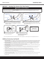
18 in. (457mm)
Push the light engine segments
down into the light guide.
Install a minimum of one clip per
18 in. (457mm) using #10 (M4)
screws.
Using the light guide final length,
measure out the necessary length
of Contour LED light engine
to match. If required, using a
sharp cutting tool, cut wire loops
between sections or through
light engine (refer to the Cutting
Resolution Table on page 2).
Installation
3/8in. (10mm)
Cut
wiring at
top
Uncut
wiring at
bottom
Attach Tetra Contour to the
mountingclips, leaving a 3/8 in.
(10mm) gap between sections
to allow for expansion or
contraction.
For vertical or near vertical
installations, any cut-end
termination of a Contour
piece shall reside at the top
of the design.
Secure light guide by twisting
tie-wire around the mounting clip
and light guide.
Fill both end caps with
silicone and install
Plan the layout by measuring the design layout and dividing by 8 ft . (2.44m) to determine the
required quantity of Tetra Contour. Refer to the Cutting Resolution Table on page 2 when cutting
any Tetra Contour section.
Do not use more than one suffix code for each respective application, as mixing suffix codes may
result in appearance variation. Suffix code can be found on the packaging label.
Installation methods shown are for straight runs. For custom shapes, refer to the Light Guide Forming Instructions.
DO NOT bend the light engine to an inside radius that is tighter than 3/4 in. (19mm). The light engine is not intended for excessive
or repetitive bending or stretching. If the silicone does crack, electrical grade silicone can be applied to seal the crack.
Planning First
Mounting orientation if
moisture may accumulate
inside light guide.
1 2 3
4 5 6
METHOD A - Installing Light Engines With Light Guides
WARNING/
AVERTISSEMENT
RISK OF FIRE: The light engine
is not intended for excessive or
repetitive bending or stretching. If
the silicone does crack, replace the
light engine.
RISQUE D’INCENDIE: Les
modules DEL Contour ne sont pas
conçus pour des pliages excessifs,
répétitifs ou pour être étirés. Si
le silicone montre des signes de
craquement, remplacer le module
DEL Contour.
If you have questions about these instructions or your Contour application, contact support at [email protected]

Installation Guide
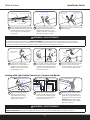
4
Tetra® Contour
Insert wire connectors into
weather box. Fill with electrical
grade silicone and close box.
Weather box can be mounted
using #8 (M3) screws.
Bends having an inside radius 1½”
or smaller must have electrical
grade silicone applied directly to
the light engine across the bend.
DO NOT bend the light engine
to an inside radius that is tighter
than 3/4 in. (19mm).
Radius
¾”–1½”
Light engine
For uncut end, fold wire over Tetra
Contour. Fill the end cap with
silicone and push cap on the end
to secure. Clean excess silicone.
Cut end:
separate wires
Electrical grade
silicone
Electrical
grade
silicone
Electrical
grade
silicone
Wire
For cut end, manually untwist and
separate wires to avoid shorts. Fill
cap with electrical grade silicone
and push cap on the end to seal.
Clean excess silicone.
Linear: At each gap between
sections, apply silicone on
both sides to secure light
guide connector. Snap on a
light guide connector.
Corner: For all corners (planar,
inside, outside) apply silicone on
both sides to secure light guide
corners. Snap on corner. Follow
Steps 8-10 if wires are cut.
Joining with Light Guide Connectors, Corners and Bends
Do not
bend one
light into a
corner
Weather box
can be painted
++
++–
–
Connect two
negatives (–)
Connect four
positives (+)
Separate wires
Use twist-on wire connectors to join
wires together.
To connect two light engines
separate wires and identify outer
conductors as positive (+) and
middle conductors as negative (–).
Strip ends back 0.5 in. (13mm).
Wires between light guide segments
can be folded behind the light guide
and attached with clear zip ties. Zip
ties should wrap around outside
light guide.
Light guide
Wire loops Light engine (back)
7 8 9
10 11 12
14 15
13
WARNING / AVERTISSEMENT
RISK OF FIRE: Waterproof wire connection and all cut ends for outdoor or wet installations. Weather box is required for all outdoor
or wet locations electrical connections. / RISQUE D’INCENDIE: Étanchéifier les connexions électriques et sceller l’extrémité
des sections coupées effectuées à l’extérieur ou pour un environnement exposé à l’eau. Un boitier étanche est requis pour les
connexions électriques effectuées à l’extérieur ou dans un environnement avec exposition à l’eau.
WARNING / AVERTISSEMENT
RISK OF FIRE: DO NOT bend the light engine to an inside radius that is tighter than 3/4 in. (19mm).
RISQUE D’INCENDIE: Ne pas plier les modules DEL Contour avec un rayon de courbure inférieur à 3/4 pouce (19 mm).

Installation Guide
5
Tetra® Contour
Weather box can be painted
Insert wire connectors into
weather box. Fill with electrical
grade silicone and close box.
Secure the weather box using a
#6 or #8 (M2 or M3) screw.
++
–
Power
supply
To Tetra Contour
Red (+)
Black or blue (–)
To power supply
Red (+)
Middle wire (–) Outer wires (+)
Connect the two outer wires (+)
from the LED strip to the red wire
(+) of the power supply. Connect
the middle wire (-) from the LED
strip to the black or blue wire (-)
of the power supply.Grounding
and bonding must be done in
accordance with National Electrical
Code (Article 600). See power
supply instructions.
Run a wire from the power supply
to a section of Tetra Contour.
Power supply connection must be
completed in an acceptable UL/
NEMA enclosure. Power supply
loading is described in the power
supply installation instructions.
Separate wires and identify outer
conductors as positive (+) and
middle conductor as negative (-).
Strip ends back 0.5 in. (13mm).
Black or blue (–)
Connect Power Supply
Plan the layout by measuring the design layout and dividing by 8 ft . (2.44m) to determine the required quantity of Tetra
Contour. Refer to the Cutting Resolution Table on page 2 when cutting any Tetra Contour section.
Do not use more than one suffix code for each respective application, as mixing suffix codes may result in appearance
variation. Suffix code can be found on the packaging label.
Installation methods shown are for straight runs. For custom shapes, install mounting clips at regular intervals throughout the shape
to provide adequate support for the light engine.
DO NOT bend the light engine to an inside radius that is tighter than 3/4 in. (19mm). The light engine is not intended for excessive
or repetitive bending or stretching. If the silicone does crack, electrical grade silicone can be applied to seal the crack.
Planning First
If you have questions about these instructions or your Contour application, contact support at [email protected]
16 17 18
19
20
WARNING/
AVERTISSEMENT
RISK OF ELECTRICAL SHOCK:
Turn power OFF before
inspection, installation or removal.
RISQUES DE CHOC ÉLECTRIQUE:
Coupez l’alimentation électrique
avant d’inspecter, d’installer ou de
déplacer le luminaire.
WARNING / AVERTISSEMENT
RISK OF FIRE: Light engine by itself is intended for use in dry indoor application only.
RISQUES DE D’INCENDIE: Les modules DEL Contour utilisés seuls sont conçus pour les environnements intérieurs secs seulement.
METHOD B - Installing Light Engines Without Light Guides (Dry Indoor Only)

Installation Guide
6
Tetra® Contour
5-8 in. (127-203mm)
Push into clips
Connect two
negatives (–) Connect four
positives (+)
++
++–
–
Separate wires
Push each 16 in. (406mm) light
engine segment into the clips. Fold
loose wires behind light engines.
Do not stretch light engines.
Install a mounting clip, using #6
(M2) counter sink screws, every 5–8
inches (127–203mm) on center until
the end of the run is reached.
Installation
Using the light engine final length,
measure out the necessary length
of Contour light engine. If required,
using a sharp cutting tool, cut wire
loops between sections or through
light engine.
Use twist-on wire connectors to
join cut wires together. Fold wires
behind light engines.
Separate wires and identify outer
conductors as positive (+) and
middle conductors as negative (–).
Strip ends back 0.5 in. (13mm).
Cut end:
separate wires
For cut end, manually untwist and
separate wires to avoid shorts. Seal
light engine end with electrical
grade silicone. Clean excess
silicone.
++
–
Power
supply
To Tetra Contour
Red (+)
Black or blue (-)
To power supply
Red (+)
Middle wire (–) Outer wires (+)
Connect the two outer wires (+)
from the LED strip to the red
wire (+) of the power supply.
Connect the middle wire (-) from
the LED strip to the black or blue
wire (-) of the power supply.
Grounding and bonding must be
done in accordance with National
Electrical Code (Article 600). See
power supply instructions.
Run a wire from the power supply
to a section of Tetra Contour.
Power supply connection must be
completed in an acceptable UL/
NEMA enclosure. Power supply
loading is described in the power
supply installation instructions.
Separate wires and identify outer
conductors as positive (+) and
middle conductor as negative (-).
Strip ends back 0.5 in. (13mm).
Black or blue (-)
Connect Power Supply
1 2 3
4 5 6
7 8 9
WARNING/
AVERTISSEMENT
RISK OF ELECTRICAL SHOCK:
Turn power OFF before
inspection, installation or removal.
RISQUES DE CHOC ÉLECTRIQUE:
Coupez l’alimentation électrique
avant d’inspecter, d’installer ou de
déplacer le luminaire.

Installation Guide
7
Tetra® Contour
Tetra Contour LS
+
++–
–
Tetra Contour
White wire with
red stripe
Tetra Contour LS
Tetra Contour
Outside wires (+)
Center wire (–)
White wire with red stripe (+)
White wire (–)
Splice the white wire with red stripe (+) of Tetra Contour
LS to the two outside wires (+) of Tetra Contour and
splice the white wire (-) of Tetra Contour LS to the center
wire (-) of Tetra Contour.
Tetra Contour LS can be connected to formable Tetra
Contour for custom shapes. Separate wires and identify
conductors as positive (+) and negative (–). Strip ends
back 0.5 in. (13mm).
Weather box can be painted
Insert wire connectors into weather
box. Fill with electrical grade
silicone and close box.
Secure the weather box using a
#6 or #8 (M2 or M3) screw. When
using twist-on connectors, weather
box is required for all outdoor
electrical connections.
NOTE: For assembling
accessories like
connectors and
corners, see Page 4.
1. (Existing Signs Only) Prior to installation, survey the site for information regarding power and accessibility inside and outside the building.
Ensure that the branch circuit supplying the existing transformer or ballast will be within the voltage ratings of the new LED power supply,
and have a current rating not exceeding 20A, or that permitted by applicable local, state, or country electrical codes (whichever is less).
2. (Existing Signs Only) Remove the existing lighting equipment to be replaced, such as neon tubing or fluorescent tubes; and associated
transformers and ballasts. Care should be taken not to break the existing neon or fluorescent tubes. NOTE: Follow all federal and local
regulations when disposing of neon tubing, fluorescent tubes, transformers and ballasts.
3. (Existing Signs Only) If removal of the existing lighting equipment eliminates the disconnect switch, as required by applicable local, state,
or country electrical codes; a new disconnect switch must be installed.
4. (Existing Signs Only) Repair and seal any unused openings in the electrical enclosure. Openings greater than 12.7-mm (1/2-in) diameter
require a metal patch secured by screws or rivets and caulked with non-hardening caulk. Smaller openings may be sealed with non-
hardening caulk.
5. Using the layout guidelines above, determine required number of LED modules required to illuminate the sign.
6. A 24VDC Class 2 Power Supply, as listed below, must be used with this retrofit kit. Determine the number of Power Supplies required to
power the number of LED modules required to illuminate the sign, so as not to overload the Power Supply chosen.
7. Follow Method A, B or C to mount the Tetra Contour.
8. Connect the DC output of the power supply to the LED modules using the Electrical Connections instructions above.
9. Connect the power unit to the supply in accordance with the applicable local, state, and country electrical codes, and the instructions found
in the power supply installation guide.
10. If required, the disconnect switch shall be installed by qualified personnel, in accordance with applicable local, state, and country
electrical codes.
Additional Instructions for Retrofit
If you have questions about these instructions or your Contour application, contact support at [email protected]
1 2
3 4
WARNING / AVERTISSEMENT
RISK OF FIRE: Waterproof wire connection for outdoor or wet installations. Weather box is required for all outdoor or wet
locations electrical connections. / RISQUE D’INCENDIE: Étanchéifier les connexions électriques effectuées à l’extérieur ou pour
un environnement exposé à l’eau. Un boitier étanche est requis pour les connexions électriques effectuées à l’extérieur ou dans un
environnement avec exposition à l’eau.
METHOD C - Attaching Tetra Contour LS to Tetra Contour

Installation GuideTetra® Contour
Troubleshooting
Symptom Condition Solution
All LEDs are OFF No AC input. Attach AC input and/or check circuit breaker.
Incorrect wire attachment. Check wire connection(s) at the Tetra Contour LED light engine and power supply
for improper connections or short circuits. Make sure you have positive to positive
and negative to negative wire connections.
Some LEDs
appear dim Overload (maximum load exceeded). Ensure the overall length of Tetra Contour LED light engine does not exceed the
maximum load as detailed in the Tetra Power Supply Installation Instructions.
Maximum recommended supply wire
length exceeded. Reduce the length of supply wire equal to or below the
recommended maximum.
Mixed Suffix Codes of LED light engine
within an application. Make sure that all LED light engines have the same Suffix Code (Suffix Code is
located on each packaging label).
Some of the
sections are not
illuminated
Incorrect wire attachment. Check the wire connections at the Tetra Contour LED light engine for improper
connections. Make sure you have positive to positive and negative to negative wire
connections. Check for improper cutting resolution locations (see Item 21 on Page 2).
Light/dark banding
along a section LED light engine stretched
during installation. Remove LED light engine and properly install.
Inspect and replace light engine if the silicone is damaged.
Power Supply
Wattage
18 AWG/0.82 mm2
Supply Wire
16 AWG/1.31 mm2
Supply Wire
14 AWG/2.08 mm2
Supply Wire
12 AWG/3.31 mm2
Supply Wire
25W 20 ft./6.1 m – – –
60W, 80W, 100W,
180W, 200W, 300W 20 ft./6.1 m 30 ft./9.1 m 50 ft./15.2 m 86 ft./26.1 m
Maximum Remote Mounting Distance
Maximum Loading per 24 VDC Class 2 Power Supply
Power Supply
GEXNRD-1,
GEXNBL-1, GEXNGL-1 GEXNYG-1, GEXNRC-1 GEXN65-1, GEXN32-1
Rating per module 24VDC, 1.52W/ft. (Strip)
1.79W/ft. (System)
24VDC, 2.27W/ft. (Strip)
2.67W/ft. (System)
24VDC, 3.17W/ft. (Strip)
3.73W/ft. (System)
GEPS24-25U-NA
Load shall not exceed 1.04A 14ft. (4.27 m) 8 ft. (2.44 m) 6 ft. (1.83 m)
GEPS24D-60U-GLX, *GELP24-60U-GL
Load shall not exceed 2.5A 36 ft. (10.97 m) 24 ft. (7.31 m) 17 ft. (5.18 m)
GEPS24D-80U, GEPS24W-80
Load shall not exceed 3.3A 50 ft. (15.24 m) 33 ft. (10.06 m) 24 ft. (7.3 m)
GEPS24-100U-GLX, GEPS24D-100U-NA,
GEPS24LT-100U-NA, USVI-100024FBA,
USVI-100024FE, GEPS24-100U-GLX2/TT,
**GEPS24V50-100W
Load shall not exceed 4.0A
59 ft. (17.9 m) 40 ft. (12.19 m) 29 ft. (8.8 m)
GEPS24-180U
Load shall not exceed 3.8A per each (of 2) banks
55 ft. (16.76 m) per bank
110 ft. (33.53 m) per PS
37 ft. (11.28 m) per bank
74 ft. (22.55 m) per PS
27 ft. (8.2 m) per bank
54 ft. (16.4 m) per PS
GEPS24-200U-GLX2
Load shall not exceed 4.0A per each (of 2) banks
59 ft. (17.9 m) per bank
118 ft. (35.8 m) per PS
40 ft. (12.1 m) per bank
80 ft. (24.2 m) per PS
29 ft. (8.8 m) per bank
87 ft. (26.5 m) per PS
GEPS24-300U-GLX2
Load shall not exceed 4.0A per each (of 3) banks
59 ft. (17.9 m) per bank
177 ft. (53.9 m) per PS
40 ft. (12.1 m) per bank
120 ft. (36.5 m) per PS
29 ft. (8.8 m) per bank
87 ft. (26.5 m) per PS
*GELP24-60U-GL minimum load = 14 ft. (4.27 m) for GEXNRD-1, GEXNBL-1, and GEXNGL-1; 9 ft. (2.74 m) for GEXNYG-1 and GEXNRC-1; or
7 ft. (2.13 m) for GEXN65-1 and GEXN32-1.
**GEPS24V50-100W minimum load = 28 ft. (8.53 m) for GEXNRD-1, GEXNBL-1, and GEXNGL-1; 19 ft. (5.79 m) for GEXNYG-1 and GEXNRC-1; or
14 ft. (4.27 m) for GEXN65-1 and GEXN32-1
LED.com
© 2023 Current Lighting Solutions, LLC. All rights reserved. Information and specifications subject to change
without notice. All values are design or typical values when measured under laboratory conditions.
Page 8 of 8
(Rev 06/19/23)
SIGN174 | GE2024-0587
-
 1
1
-
 2
2
-
 3
3
-
 4
4
-
 5
5
-
 6
6
-
 7
7
-
 8
8


Tetra Contour LED Signage Guide d'installation
- Taper
- Guide d'installation
dans d''autres langues
Documents connexes
-
Tetra Contour LS LED Signage Guide d'installation
-
-
-
-
-
-
-
-
-
Autres documents
-
GE Appliances SIGN171 Guide d'installation
-
GE current GEXNBL-1 Guide d'installation
-
Lumination Contour Series LED Architectural Lighting Guide d'installation
-
GE current GEDS Series Guide d'installation
-
GE current GEXNB32-2 Guide d'installation
-
 Immersion Elite Gen 2 Vertical Case Center Mullion Lights Guide d'installation
-
 Immersion Elite Gen 2 French Door End Mullion Lights Guide d'installation
-
 Immersion LED DIsplay Lighting Elite Series Horizontal Guide d'installation
-
 GE current SIGN159EU Guide d'installation


