Thermal Arc 160 TS ARCMASTER Manuel utilisateur
- Catégorie
- Système de soudage
- Taper
- Manuel utilisateur
Ce manuel convient également à


WE APPRECIATE YOUR BUSINESS!
Congratulations on your new Thermal Arc® product. We are proud to
have you as our customer and will strive to provide you with the best
service and reliability in the industry. This product is backed by our
extensive warranty and world-wide service network. To locate your
nearest distributor or service agency call 800-752-7621, or visit us
on the web at www.thermalarc.com.
This Operating Manual has been designed to instruct you on the correct
use and operation of your Thermal Arc® product. Your satisfaction with
this product and its safe operation is our ultimate concern. Therefore,
please take the time to read the entire manual, especially the Safety
Precautions. They will help you to avoid potential hazards that may
exist when working with this product.
YOU ARE IN GOOD COMPANY!
The Brand of Choice for Contractors and Fabricators Worldwide.
Thermal Arc® is a Global Brand of Arc Welding Products for Thermadyne
Industries Inc. We manufacture and supply to major welding industry
sectors worldwide including; Manufacturing, Construction, Mining,
Automotive, Aerospace, Engineering, Rural and DIY/Hobbyist.
We distinguish ourselves from our competition through market-
leading, dependable products that have stood the test of time. We
pride ourselves on technical innovation, competitive prices, excellent
delivery, superior customer service and technical support, together
with excellence in sales and marketing expertise.
Above all, we are committed to develop technologically advanced
products to achieve a safer working environment within the welding
industry.

i
!
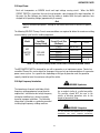
WARNINGS
Read and understand this entire Manual and your employer’s safety practices before installing, operating,
or servicing the equipment.
While the information contained in this Manual represents the Manufacturer’s best judgment, the
Manufacturer assumes no liability for its use.
Service Manual Number 0-4881B for:
ArcMaster 160 TS Inverter Welding Power Supply Part No. 10-3067
Published by:
Thermadyne Industries, Inc.
82 Benning Street
West Lebanon, New Hampshire, USA 03784
(603) 298-5711
www.thermalarc.com
Copyright © 2006, 2007, 2008 by
Thermadyne Industries, Inc.
® All rights reserved.
Reproduction of this work, in whole or in part, without written permission of the publisher
is prohibited.
The publisher does not assume and hereby disclaims any liability to any party for any loss
or damage caused by any error or omission in this Manual, whether such error results
from negligence, accident, or any other cause.
Publication Date: June 16, 2006
Revision AB Date: June 5, 2008
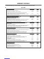
Record the following information for Warranty purposes:
Where Purchased: _______________________________
Purchase Date: _______________________________
Equipment Serial #: _______________________________

1
CONTENTS
SECTION 1: SAFETY INSTRUCTIONS AND WARNINGS....................................................................................................3
1.01 Arc Welding Hazards ...........................................................................................................................................3
1.02 PRINCIPAL SAFETY STANDARDS .......................................................................................................................7
1.03 PRECAUTIONS DE SECURITE EN SOUNDAGE A L’ARC.......................................................................................8
1.04 Dangers relatifs au soudage à l’arc......................................................................................................................8
1.05 PRINCIPAL SAFETY STANDARDS .....................................................................................................................12
SECTION 2: INTRODUCTION ..........................................................................................................................................13
2.01 How To Use This Manual....................................................................................................................................13
2.02 Equipment Identification.....................................................................................................................................13
2.04 Symbol Chart......................................................................................................................................................14
2.05 Description.........................................................................................................................................................15
2.06 Functional Block Diagrams .................................................................................................................................16
2.07 Transporting Methods ........................................................................................................................................16
SECTION 3: INSTALLATION ..........................................................................................................................................17
3.01 Environment.......................................................................................................................................................17
3.02 Location .............................................................................................................................................................17
3.03 Electrical Input Connections ...............................................................................................................................17
3.04 Electrical Input Requirement...............................................................................................................................18
3.05 Input Power........................................................................................................................................................19
3.06 High Frequency Introduction ..............................................................................................................................19
3.07 High Frequency Interference...............................................................................................................................20
3.08 Duty Cycle ..........................................................................................................................................................20
3.09 Specifications .....................................................................................................................................................21
SECTION 4: OPERATOR CONTROLS .............................................................................................................................23
4.01 ARC MASTER 160TS Controls............................................................................................................................23
4.02 Weld Process selection for 160TS......................................................................................................................25
4.03 Weld Parameter Descriptions for ARC MASTER 160TS......................................................................................26
4.04 Weld Parameters for ARC MASTER 160TS.........................................................................................................29
4.05 Power Source Features.......................................................................................................................................30
SECTION 5: SET-UP FOR SMAW (STICK) AND GTAW (TIG)..........................................................................................31
SECTION 6: SEQUENCE OF OPERATION........................................................................................................................32
6.01 Stick Welding .....................................................................................................................................................33
6.02 HF TIG & Lift TIG Welding ..................................................................................................................................33
6.03 Slope Mode Sequence ........................................................................................................................................34
6.04 Slope Mode with repeat sequence ......................................................................................................................34
6.05 Pulse Controls ....................................................................................................................................................35
SECTION 7: ROUTINE MAINTENANCE...........................................................................................................................36
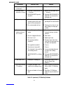
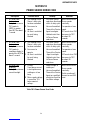
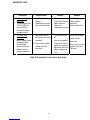
SECTION 8: BASIC TROUBLESHOOTING.......................................................................................................................38
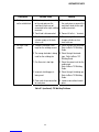
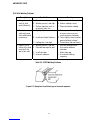
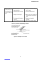
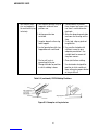
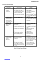
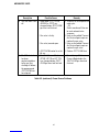
8.01 TIG Welding Problems........................................................................................................................................38
8.02 Stick Welding Problems .....................................................................................................................................41
8.03 Power Source Problems.....................................................................................................................................44
SECTION 9: VOLTAGE REDUCTION DEVICE (VRD)..........................................................................................46
9.01 VRD Specification...............................................................................................................................................46
9.02 VRD Maintenance...............................................................................................................................................46
9.03 Switching VRD On/Off ........................................................................................................................................49
SECTION 10: POWER SOURCE ERROR CODE .....................................................................................................50

2
CONTENTS
SECTION 11: ADVANCED TROUBLE SHOOTING............................................................................................... 52
11.01 System-Level Fault Isolation ............................................................................................................................ 52
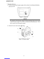
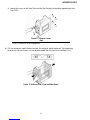
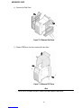
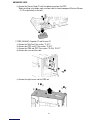
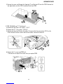
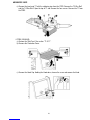
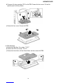
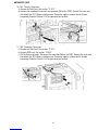
1. Opening the Enclosure....................................................................................................................................... 53
11.02 Verification and Remedy to the Indicated Error Codes ..................................................................................... 56
1. E01 “Over-Temperature at the primary side”...................................................................................................... 57
2. E02 “Over-Temperature at the secondary side”.................................................................................................. 57
3. E03 “Primary Over-Current Failure” .................................................................................................................. 58
4. E94 “Thermistor malfunction”............................................................................................................................ 58
5. E99 “Initial Power Receiving”............................................................................................................................. 58
11.03 Verification and Remedy to Failures without Indication Codes .........................................................................59
1. “Cooling Fan (FAN1) Failure” (Fan is not rotating.).............................................................................................59
2. “Gas Valve Failure” (No Gas flow through unit)..................................................................................................59
3. “No Weld Output” .............................................................................................................................................. 60
4. “Operating Panel Failure” (LED’s do not light properly or welding setting cannot be established.)..................... 61
5. “High Frequency Output Failure” (Unit does not generate High Frequency.)....................................................... 61
11.04 Fault Isolation Tests......................................................................................................................................... 62
11.05 Verification of the Power Input Circuitry........................................................................................................... 63
1. Verification of the AC input voltage using an AC voltmeter................................................................................. 63
2. Verification of the Power Supply Voltage ........................................................................................................... 65
3. Verification of the Cooling Fan, FAN1, Drive Circuitry......................................................................................... 67
4. Verification of the Gas Valve, SOL1, Drive Circuitry............................................................................................ 68
5. Verification of the primary Diode (D1)................................................................................................................69
6. Verification of the secondary Diode (D2, D3) ..................................................................................................... 70
7. Verification of the primary IGBT (Q1A-Q4C)....................................................................................................... 71
8. Verification of No-load Voltage (OCV) ................................................................................................................ 72
9. Output Load Test ............................................................................................................................................... 73
SECTION 12: MAINTENANCE ................................................................................................................................ 74
12.01 Maintenance List.............................................................................................................................................. 74
12.02 Service Tools ................................................................................................................................................... 77
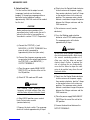
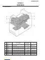
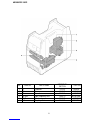
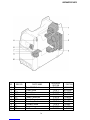
12.03 Replacement Procedure................................................................................................................................... 78
1. PCB1 (WK-5466) and Primary Diode D1............................................................................................................ 78
2. PCB2 (WK-5467), Capacitor C1 and Resistor R1 ............................................................................................... 81
3. PCB3 (WK-5609) and T1 “Transformer” ............................................................................................................ 82
4. PCB4 (WK-5449) ............................................................................................................................................... 83
5. PCB5 (WK-5448) ............................................................................................................................................... 84
6. PCB6 (WK-5460) and Q1A-Q2C “Primary IGBT”................................................................................................ 85
7. PCB7 (WK-5460) and Q3A-Q4C “Primary IGBT”................................................................................................ 86
8. D2 and D3 “Secondary Diode” ........................................................................................................................... 86
9. C.C. “Coupling Coil”* and FCH1 “Reactor” *160TS only................................................................................... 87
10. CT1 “Hole Current Trans”................................................................................................................................. 88
11. FAN1 “Cooling Fan” .........................................................................................................................................89
12. HF UNIT1 “High Frequency Unit” *160TS only................................................................................................ 90
13. SOL1 “Solenoid GAS Valve” *160TS only ....................................................................................................... 90
14. S1 “Switch” ..................................................................................................................................................... 91
15. CON1 “Remote Receptacle” ............................................................................................................................. 92
16. TH1 “Primary Thermistor” ............................................................................................................................... 93
17. TH2 “Secondary Thermistor” ........................................................................................................................... 93
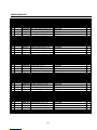
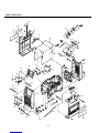
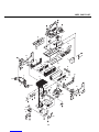
APPENDIX A: PARTS LIST....................................................................................................................................... 95
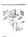
APPENDIX B: CONNECTION WIRING GUIDE.................................................................................................... 100
1. Connection Guide................................................................................................................................................. 100
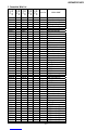
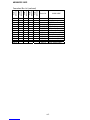
2. Connection Wire List............................................................................................................................................ 101
APPENDIX C: CONNECTION DIAGRAM............................................................................................................. 103
APPENDIX D: DIODE TESTING BASICS............................................................................................................... 105


ARCMASTER 160TS
3
SECTION 1:
SAFETY INSTRUCTIONS AND WARNINGS
WARNING
PROTECT YOURSELF AND OTHERS FROM POSSIBLE SERIOUS INJURY OR DEATH. KEEP CHILDREN AWAY.
PACEMAKER WEARERS KEEP AWAY UNTIL CONSULTING YOUR DOCTOR. DO NOT LOSE THESE INSTRUCTIONS. READ
OPERATING / INSTRUCTION MANUAL BEFORE INSTALLING, OPERATING OR SERVICING THIS EQUIPMENT.
Welding products and welding processes can cause serious injury or death, or damage to other equipment or property, if
the operator does not strictly observe all safety rules and take precautionary actions.
Safe practices have developed from past experience in the use of welding and cutting. These practices must be learned
through study and training before using this equipment. Some of these practices apply to equipment.
CONNECTED TO POWER LINES; other practices apply to engine driven equipment. Anyone not having extensive training in
welding and cutting practices should not attempt to weld.
Safe practices are outline in the American National Standard Z49.1 entitled: SAFETY IN WELDING AND CUTTING. This
publication and other guides to what you should learn before operating this equipment are listed at the end of these safety
precautions. HAVE ALL INSTALLATION, OPERATION, MAINTENANCE, AND REPAIR WORK PERFORMED ONLY BY
QUALIFIED PEOPLE.
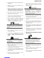
1.01 Arc Welding Hazards
WARNING
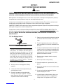
ELECTRIC SHOCK can kill
Touching live electrical parts can cause fatal shocks or
severe burns. The electrode and work circuit is
electrically live whenever the output is on. The input
power circuit and machine internal circuits are also
live when power is on. In semiautomatic or automatic
wire welding, the wire, wire reel, drive roll housing,
and all metal parts touching the welding wire are
electrically live. Incorrectly installed or improperly
grounded equipment is a hazard.
1. Do not touch live electrical parts.
2. Wear dry, hole-free insulating gloves and body
protection.
3. Insulate yourself from work and ground using dry
insulating mats or covers.
4. Disconnect input power or stop engine before
installing or servicing this equipment. Lock input
power disconnect switch open, or remove line fuses
so power cannot be turned on accidentally.
5. Properly install and ground this equipment according
to its Owner’s Manual and national, state, and local
codes.
6. Turn off all equipment when not in use. Disconnect
power to equipment if it will be left unattended or out
of service.
7. Use fully insulated electrode holders. Never dip holder
in water to cool it or lay it down on the ground or the
work surface. Do not touch holders connected to two
welding machines at the same time or touch other
people with the holder or electrode.
8. Do not use worn, damaged, undersize, or poorly
spliced cables.
9. Do not wrap cables around your body.
10. Ground the workpiece to a good electrical (earth)
ground.
11. Do not touch electrode while in contact with the work
(ground) circuit.
12. Use only well-maintained equipment. Repair or
replace damaged parts at once.
13. In confined spaces or damp locations, do not use a
welder with AC output unless it is equipped with a
voltage reducer. Use equipment with DC output.

ARCMASTER 160TS
4
14. Wear a safety harness to prevent falling if working
above fool level.
15. Keep all panels and covers securely in place.
WARNING
ARC RAYS can burn eyes and skin; NOISE can
damage hearing.
Arc rays from the welding process produce intense
heat and strong ultraviolet rays that can eyes and skin.
Noise from some processes can damage hearing.
1. Wear a welding helmet fitted with a proper shade of
filter (see ANSI Z49.1 listed in Safety Standards) to
protect your face and eyes when welding or watching.
2. Wear approved safety glasses. Side shields
recommended.
3. Use protective screens or barriers to protect others
from flash and flare; warn others not to watch the arc.
4. Wear protective clothing made from durable, flame-
resistant material (wool and lather) and foot
protection.
5. Use approved ear plugs or ear muffs if noise level is
high.
WARNING
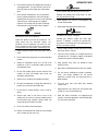
FUMES AND GASES can be hazardous your health.
Welding produces fumes and gases. Breathing these
fumes and gases can be hazardous to your health.
1. Keep your head out of the fumes. Do not breath the
fumes.
2. If inside, ventilate the area and/or use exhaust at the
arc to remove welding fumes and gases.
3. If ventilation is poor, use an approved air-supplied
respirator.
4. Read the Material Safety Data Sheets (MSDSs) and
the manufacturer’s instruction for metals,
consumables, coatings, and cleaners.
5. Work in a confined space only if it is well ventilated, or
while wearing an air-supplied respirator. Shielding
gases used for welding can displace air causing injury
or death. Be sure the breathing air is safe.
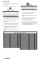
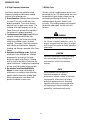
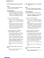
Eye protection filter shade selector for welding or cutting
(goggles or helmet), from AWS A6.2-73.
Welding or cutting Electrode Size
Filter Welding or cutting Electrode Size Filter
Torch soldering 2 Gas metal-arc
Torch brazing 3 or 4 Non-ferrous base metal All 11
Oxygen Cutting Ferrous base metal All 12
Light Under 1 in., 25mm 3 or 4 Gas tungsten arc welding All 12
Medium 1 to 6 in., 25-150mm 4 or 5 (TIG) All 12
Heavy Over 6 in., 150mm 5 or 6 Atomic hydrogen welding All 12
Gas welding Carbon arc welding All 12
Light Under 1/8 in., 3mm 4 or 5 Plasma arc welding
Medium 1/8 to 1/2 in., 3-12mm 5 or 6 Carbon arc air gouging
Heavy Over 1/2 in., 12mm 6 or 8 Light 12
Shielded metal-arc Under 5/32 in., 4mm 10 Heavy 14
5/32 to 1/4 in., 12 Plasma arc cutting
Over 1/4 in., 6.4mm 14 Light Under 300 Amp 9
Medium 300 to 400 Amp 12
Heavy Over 400 Amp 14

ARCMASTER 160TS
5
6. Do not weld in locations near degreasing, cleaning, or
spraying operations. The heat and rays of the arc can
react with vapors to from highly toxic and irritating
gases.
7. Do not weld on coated metals, such as galvanized,
lead, or cadmium plated steel, unless the coating is
removed from the weld area, the area is well ventilated,
and if necessary, while wearing an air-supplied
respirator. The coatings and any metals containing
these elements can give off toxic fumes if welded.
WARNING
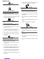
WELDING can cause fire or explosion.
Sparks and spatter fly off from the welding arc. The
flying sparks and hot metal,weld spatter, hot
workpiece, and hot equipment can cause fires and
burns. Accidental contact of electrode or welding wire
to metal objects can cause sparks, overheating, or fire.
1. Protect yourself and others from flying sparks and hot
metal.
2. Do not weld where flying sparks can strike flammable
material.
3. Remove all flammables within 35 ft (10.7m) of the
welding arc. If this is not possible, tightly cover them
with approved covers.
4. Be alert that welding sparks and hot materials from
welding can easily go through small cracks and
openings to adjacent areas.
5. Watch for fire, and keep a fire extinguisher nearby.
6. Be aware that welding on a ceiling, floor, bulkhead, or
partition can cause fire on the hidden side.
7. Do not weld on closed containers such as tanks or
drums.
8. Connect work cable to the work as close to the
welding area as practical to prevent welding current
from traveling long, possibly unknown paths and
causing electric shock and fire hazards.
9. Do not use welder to thaw frozen pipes.
10. Remove stick electrode from holder or cut off welding
wire at contact tip when not in use.
WARNING
FLYING SPARKS AND HOT METAL can cause injury.
Chipping and grinding cause flying metal. As weld
cool, they can throw off slag.
1. Wear approved face shield or safety goggles. Side
shields recommended.
2. Wear proper body protection to protect skin.
WARNING
CYLINDERS can explode if damaged.
Shielding gas cylinders contain gas under high
pressure. If damaged, a cylinder can explode.Since
gas cylinders are normally part of the welding process,
be sure to treat them carefully.
1. Protect compressed gas cylinders from excessive heat,
mechanical shocks, and arcs.
2. Install and secure cylinders in an upright position by
chaining them to a stationary support or equipment
cylinder rack to prevent falling or tipping.
3. Keep cylinders away from any welding or other
electrical circuits.
4. Never allow a welding electrode to touch any cylinder.
5. Use only correct shielding gas cylinders, regulators,
hoses, and fittings designed for the specific
application; maintain them and associated parts in
good condition.
6. Turn face away from valve outlet when opening
cylinder valve.
7. Keep protective cap in place over valve except when
cylinder is in use or connected for use.
8. Read and follow instructions on compressed gas
cylinders, associated equipment, and CGA publication
P-1 listed Safety Standards.

ARCMASTER 160TS
6
WARNING
Engines can be dangerous.
WARNING
ENGINE EXHAUST GASES can kill.
Engines produce harmful exhaust gases.
1. Use equipment outside in open, well-ventilated areas.
2. If used in a closed area, vent engine exhaust outside
and away from any building air intakes.
WARNING
ENGINE FUEL can cause fire or explosion.
Engine fuse is highly flammable.
1. Stop engine before checking or adding fuel.
2. Do not add fuel while smoking or if unit is near any
sparks or open flames.
3. Allow engine to cool before fueling. If possible, check
and add fuel to cold engine before beginning job.
4. Do not overfill tank – allow room for fuel to expand.
5. Do not spill fuel. If fuel is spilled, clean up before
stating engine.
WARNING
MOVING PARTS can cause injury.
Moving parts, such as fans, rotors, and belts can cut
fingers and hands and catch loose clothing.
1. Keep all doors, panels, covers, and guards closed and
securely in place.
2. Stop engine before installing or connecting unit.
3. Have only qualified people remove guards or covers
for maintenance and troubleshooting as necessary.
4. To prevent accidental starting during servicing,
disconnect negative (-) battery cable from battery.
5. Keep hands, hair, loose clothing, and tools away from
moving parts.
6. Reinstall panels or guards and close doors when
servicing is finished and before starting engine.
WARNING
SPARKS can cause BATTERY GASES TO EXPLODE;
BATTERY ACID can burn eyes and skin.
Batteries contain acid and generate explosive gases.
1. Always ware a face shield when working on a battery.
2. Stop engine before disconnecting or connecting
battery cables.
3. Do not allow tools to cause sparks when working on a
battery.
4. Do not use welder to charge batteries or jump start
vehicles.
5. Observe correct polarity (+ and -) on batteries.
WARNING
STEAM AND PRESSURIZED HOT COOLANT can burn
face , eyes,and skin.
The coolant in the radiator can be very hot and under
pressure.
1. Do not remove radiator cap when engine is hot. Allow
engine to cool.
2. Wear gloves and put a rag over cap area when
removing cap.
3. Allow pressure to escape before completely removing
cap.

ARCMASTER 160TS
7
WARNING
This product, when used for welding or cutting,
produces fumes or gases which contain chemicals
know to the State of California to cause birth defects
and, in some cases, cancer. (California Health &
Safety code sec. 25249.5 et seq.)
NOTE
Considerations About Welding And The Effects of Low
Frequency Electric and Magnetic Fields.
The following is a quotation from the General Conclusions
Section of the U.S. Congress, Office of Technology
Assessment, Biological Effects of Power Frequency
Electric & Magnetic Fields-Background Paper, OTA-BP-E-
63 (Washington, DC; U.S. Government Printing Office,
MAY 1989): “…there is now a very large volume of
scientific findings based on experiment at the cellular level
and from studies with animals and people which clearly
establish that low frequency magnetic fields and interact
with, and produce changes in, biological systems. While
most of this work is of very high quality, the results are
complex. Current scientific understanding does not yet
allow us to interpret the evidence in a single coherent
framework. Even more frustrating, it does not yet allow us
to draw definite conclusions about questions of possible
risk or to offer clear science-based advice on strategies to
minimize or avoid potential risk.”
To reduce magnetic fields in the workplace, use the
following procedures.
1. Keep cables close together by twisting or taping
them.
2. Arrange cables to one side and away from the
operator.
3. Do not coil or drape cable around the body.
4. Keep welding power source and cables as far
away from body as practical.
ABOUT PACEMAKERS:
The above procedures are among those also
normaly recommended for pacemaker
wearers. Consult your doctor for complete
information.
1.02 PRINCIPAL SAFETY STANDARDS
Safety in Welding and Cutting, ANSI Standard Z49.1, from
the American Welding Society, 550 N.W. LeJeune Rd.,
Miami, FL 33126.
Safety and Health Standards, OSHA, 29CFR 1910, SAFETY
AND HEALTH STANDARDS, obtainable from
Superintendent of Documents, U.S. Government Printing
Office, Washington, D.C. 20402.
Recommended Safe Practices for the Preparation for
Welding and Cutting of Containers That Have Held
Hazardous Substances, American Welding Society
Standard AWSF4.1, obtainable from the American Welding
Society, 550 N.W. LeJeune Rd, Miami, FL 33126.
National Electrical Code, NFPA Standard 70, obtainable
from the National Fire Protection Association,
Batterymarch Park, Quincy, MA 02269.
Safe Handling of Compressed Gases in Cylinders, CGA
Pamphlet P-1, obtainable from the Compressed Gas
Association, 1235 Jefferson Davis Highway, Suite 501,
Arlington, VA 22202.
Code for Safety in Welding and Cutting, CSA Standard
W117.2, obtainable from the Canadian Standards
Association, Standards Sales, 178 Rexdale Boulevard,
Rexdale, Ontario, Canada M9W 1R3.
Safe Practices for Occupation and Educational Eye and
Face Protection, ANSI Standard Z87.1, obtainable from
American National Standards Institute, 1430 Broadway,
New York, NY 10018.
Cutting and Welding Processes, NFPA Standard 51B,
obtainable from the National Fire Protection Association,
Batterymarch Park, Quincy, MA 02269.

ARCMASTER 160TS
8
1.03 PRECAUTIONS DE SECURITE EN SOUNDAGE A L’ARC
MISE EN GARD
LE SOUDAGE A L’ARC EST DANGEREUX
PROTEGEZ-VOUS, AINSI QUE LES AUTRES, CONTRE LES BLESSURES GRAVES POSSIBLES OU LA MORT. NE LAISSEZ
PAS LES ENFANTS S’APPROCHER, NI LES PORTEURS DE STIMULATEUR CARDIAQUE (A MOINS QU’ILS N’AIENT
CONSULTE UN MEDECIN). CONSERVEZ CES INSTRUCTIONS. LISEZ LE MANUEL D’OPERATION OU LES INSTRUCTIONS
AVANT D’INSTALLER, UTILISER OU ENTRETENIR CET EQUIPEMENT.
Les produits et procédés de soudage peuvent sauser des blessures graves ou la mort, de meme que des dommages au
reste du matériel et à la propriété, si l’utilisateur n’adhère pas strictement à toutes les règles de sécurité et ne prend pas les
précautions nécessaires.
En soudage et coupage, des pratiques sécuritaires se sont développées suite à l’expérience passée. Ces pratiques. doivent
être apprises par étude ou entrainement avant d’utiliser l’equipement. Toute personne n’ayant pas suivi un entraînement
intensif en soudage et coupage ne devrait pas tenter de souder. Certaines pratiques concernent les équipements raccordés
aux lignes d’alimentation alors que d’autres s’adressent aux groupes électrogènes.
La norme Z49.1 de l’American National Standard, intitulée “SAFETY IN WELDING AND CUTTING” présente les pratiques
sécuritaires à suivre. Ce document ainsi que d’autres guides que vous devriez connaître avant d’utiliser cet équipement
sont présentés à la fin de ces instructions de sécurité.
SEULES DES PERSONNES QUALIFIEES DOIVENT FAIRE
DES TRAVAUX D’INSTALLATION, DE REPARTION,
D’ENTRETIEN ET D’ESSAI
1.04 Dangers relatifs au soudage à l’arc
AVERTISSEMENT
L’ELECTROCUTION PEUT ETRE MORTELLE.
Une décharge électrique peut tuer ou brûler
gravement. L’électrode et le circuit de soudage
sont sous tension dès la mise en circuit. Le
circuit d’alimentation et les circuits internes
de l’équipement sont aussi sous tension dés
la mise en marche. En soudage automatique
ou semi-automatique avec fil, ce dernier, le
rouleau ou la bobine de fil, le logement des
galets d’entrainement et toutes les pièces
métalliques en contact avec le fil de soudage
sont sous tension. Un équipement inadéquatement
installé ou inadéquatement
mis à la terre est dangereux.
1. Ne touchez pas à des pièces sous tension.
2. Portez des gants et des vêtements isolants, secs et
non troués.
3. Isolez-vous de la pièce à souder et de la mise à la
terre au moyen de tapis isolants ou autres.
4. Déconnectez la prise d’alimentation de l’équipement
ou arrêtez le moteur avant de l’installer ou d’en faire
l’entretien. Bloquez le commutateur en circuit ouvert
ou enlevez les fusibles de l’alimentation afin d’éviter
une mise en marche accidentelle.
5. Veuillez à installer cet équipement et à le mettre à la
terre selon le manuel d’utilisation et les codes
nationaux, provinciaux et locaux applicables.
6. Arrêtez tout équipement après usage. Coupez
l’alimentation de l’équipement s’il est hors d’usage ou
inutilisé.
7. N’utilisez que des porte-électrodes bien isolés. Ne
jamais plonger les porte-électrodes dans l’eau pour
les refroidir. Ne jamais les laisser traîner par terre ou
sur les pièces à souder. Ne touchez pas aux
porteelectrodes raccordes à deux sources de courant
en même temps. Ne jamais toucher quelqu’un d’autre
avec l’électrode ou le porte-électrode.
8. N’utilisez pas de cables électriques usés,
endommagés, mal épissés ou de section trop petite.
9. N’enroulez pas de câbles électriques autour de votre
corps.
10. N’utilisez qu’une bonne prise de masse pour la mise à
la terre de la pièce à souder.
11. Ne touchez pas à l’électrode lorsqu’en contact avec le
circuit de soudage (terre).
12. N’utilisez que des équipements en bon état. Réparez
ou remplacez aussitôt les pièces endommagées.
13. Dans des espaces confinés ou mouilles, n’utilisez pas
de source de courant alternatif, à moins qu’il soit

ARCMASTER 160TS
9
muni d’un réducteur de tension. Utilisez plutôt une
source de courant continu.
14. Portez un harnais de sécurité si vous travaillez en
hauteur.
15. Fermez solidement tous les panneaux et les capots.
AVERTISSEMENT
LE RAYONNEMENT DE L’ARC PEUT BRÛLER LES
YEUX ET LA PEAU; LE BRUIT PEUT ENDOMMAGER
L’OUIE.
L’arc de soudage produit une chaleur et des
rayons ultraviolets intenses, susceptibles de
brûler les yeux et la peau. Le bruit causé par
certains procédés peut endommager l’ouïe.
1. Portez une casque de soudeur avec filtre oculaire de
nuance appropriee (consultez la norme ANSI Z49
indiquee ci-aprés) pour vous protéger le visage et les
yeux lorsque vous soudez ou que vous observez
l’exécution d’une soudure.
2. Portez des lunettes de sécurité approuvées. Des
écrans latéraux sont recommandés.
3. Entourez l’aire de soudage de rideaux ou de cloisons
pour protéger les autres des coups d’arc ou de
l’éblouissement; avertissez les observateurs de ne pas
regarder l’arc.
4. Portez des vêtements en matériaux ignifuges et
durables (laine et cuir) et des chaussures de sécurité.
5. Portez un casque antibruit ou des bouchons d’oreille
approuvés lorsque le niveau de bruit est élevé.
AVERTISSEMENT
LES VAPEURS ET LES FUMEES SONT
DANGEREUSES POUR LA SANTE.
Le soudage dégage des vapeurs et des fumées
dangereuses à respirer
.
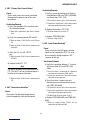
SELECTION DES NUANCES DE FILTRES OCULAIRS POUR LA PROTECTION
DES YEUX EN COUPAGE ET SOUDAGE (selon AWS à 6.2-73)
Opération de
coupage ou soudage
Dim ension d’électrode ou
Epiasseur de métal ou
Intensité de courant
Nuance
de filter
oculaire
Opération de coupage ou soudage
Dim ension d’électrode ou
Epiasseur de métal ou
Intensité de courant
Nuance
de filter
oculaire
Brassage tender au
chalumeau Toutes conditions 2 Soudage á l'arc sous gaz avec fil
plein (GMAW)
Brassage fort au
chalumeau Toutes conditions 3 ou 4 métaux non-ferreux Toutes conditions 11
Oxycoupage métaux ferreux Toutes conditions 12
mince moins de 1 po. (25mm) 3 ou 4 Soudage á l'arc sous gaz avec
électrode de tungstène (GTAW) Toutes conditions 12
moyen de 1 à 6 po. (25 à 150mm) 4 ou 5 Soudage á l'hydrogène
atomique (AHW) Toutes conditions 12
épais plus de 6 po. (150mm) 5 ou 6 Soudage á l'arc avec
électrode de carbone (CAW) Toutes conditions 12
Soudage auxgaz Soudage á l'arc Plasma (PAW) Toutes conditions 12
mince moins de 1/8 po. (3mm) 4 ou 5 Gougeage Air-Arc avec
électrode de carbone
moyen de 1/8 à 1/2 po.
(3 à 12mm) 5 ou 6 mince
épais plus de 1/2 po. (12mm) 6 ou 8 épais 12
Soudage á l'arc avec
électrode enrobes
(SMAW)
monis de 5/32 po. (4mm) 10 Coupage á l'arc Plasma (PAC) 14
5/32 à 1/4 po. (4 à 6.4mm) 12 mince monis de 300 amperés 9
plus de 1/4 po. (6.4mm) 14 moyen de 300 á 400 amperés 12
épais plus de 300 amperés 14
1. Eloignez la tete des fumées pour éviter de les respirer.
2. A l’intérieur, assurez-vous que l’aire de soudage est
bien ventilée ou que les fumees et les vapeurs sont
aspirées à l’arc.
3. Si la ventilation est inadequate, portez un respirateur à
adduction d’air approuvé.

ARCMASTER 160TS
10
4. Lisez les fiches signalétiques et les consignes du
fabricant relatives aux métaux, aux produits
consummables, aux revêtements et aux produits
nettoyants.
5. Ne travaillez dans un espace confiné que s’il est bien
ventilé; sinon, portez un respirateur a adduction d’air.
Les gaz protecteurs de soudage peuvent déplacer
l’oxygène de l’air et ainsi causer des malaises ou la
mort. Assurez-vous que l’air est propre a la
respiration.
6. Ne soudez pas à proximité d’opérations de
dégraissage, de nettoyage ou de pulvérisation. La
chaleur et les rayons de l’arc peuvent réagir avec des
vapeurs et former des gaz hautement toxiques et
irritants.
7. Ne soudez des tôles galvanisées ou plaquées au
plomb ou au cadmium que si les zones à souder ont
été grattées à fond, que si l’espace est bien ventilé; si
nécessaire portez un respirateur à adduction d’air. Car
ces revêtements et tout métal qui contient ces
éléments peuvent dégager des fumées toxiques au
moment du soudage.
AVERTISSEMENT
LE SOUDAGE PEUT CAUSER UN INCENDIE OU UNE
EXPLOSION.
L’arc produit des étincellies et des projections. Les
particules volantes, le métal chaud, les projections de
soudure et l’équipement surchauffé peuvent causer un
incendie et des brûlures. Le contact accidentel de
l’électrode ou du fil-électrode avec un objet métallique
peut provoquer des étincelles, un
échauffement ou
un incendie.
1. Protégez-vous, ainsi que les autres, contre les
étincelles et du métal chaud.
2. Ne soudez pas dans un endroit où des particules
volantes ou des projections peuvent atteindre des
matériaux inflammables.
3. Enlevez toutes matières inflammables dans un rayon
de 10, 7 mètres autour de l’arc, ou couvrez-les
soigneusement avec des bâches approuvées.
4. Méfiez-vous des projections brulantes de soudage
susceptibles de pénétrer dans des aires adjacentes
par de petites ouvertures ou fissures.
5. Méfiez-vous des incendies et gardez un extincteur à
portée de la main.
6. N’oubliez pas qu’une soudure réalisée sur un plafond,
un plancher, une cloison ou une paroi peut enflammer
l’autre côté.
7. Ne soudez pas un récipient fermé, tel un réservoir ou
un baril.
8. Connectez le câble de soudage le plus près possible
de la zone de soudage pour empêcher le courant de
suivre un long parcours inconnu, et prévenir ainsi les
risques d’électrocution et d’incendie.
9. Ne dégelez pas les tuyaux avec un source de courant.
10. Otez l’électrode du porte-électrode ou coupez le fil au
tube-contact lorsqu’inutilisé après le soudage.
11. Portez des vêtements protecteurs non huileux, tels
des gants en cuir, une chemise épaisse, un pantalon
revers, des bottines de sécurité et un casque.
AVERTISSEMENT
LES ETINCELLES ET LES PROJECTIONS BRULANTES
PEUVENT CAUSER DES BLESSURES.
Le piquage et le meulage produisent des particules
métalliques volantes. En refroidissant,
la soudure peut projeter du éclats de laitier.
1. Portez un écran facial ou des lunettes protectrices
approuvées. Des écrans latéraux sont recommandés.
2. Portez des vêtements appropriés pour protéger la
peau.
AVERTISSEMENT
LES BOUTEILLES ENDOMMAGEES PEUVENT
EXPLOSER.
Les bouteilles contiennent des gaz protecteurs sous
haute pression. Des bouteilles endommagées peuvent
exploser. Comme les bouteilles font normalement
partie du procédé de soudage, traitez-les avec soin.
1. Protégez les bouteilles de gaz comprimé contre les
sources de chaleur intense, les chocs et les arcs de
soudage.
2. Enchainez verticalement les bouteilles à un support ou
à un cadre fixe pour les empêcher de tomber ou d’être
renversées.

ARCMASTER 160TS
11
3. Eloignez les bouteilles de tout circuit électrique ou de
tout soudage.
4. Empêchez tout contact entre une bouteille et une
électrode de soudage.
5. N’utilisez que des bouteilles de gaz protecteur, des
détendeurs, des boyauxs et des raccords conçus pour
chaque application spécifique; ces équipements et les
pièces connexes doivent être maintenus en bon état.
6. Ne placez pas le visage face à l’ouverture du robinet
de la bouteille lors de son ouverture.
7. Laissez en place le chapeau de bouteille sauf si en
utilisation ou lorsque raccordé pour utilisation.
8. Lisez et respectez les consignes relatives aux
bouteilles de gaz comprimé et aux équipements
connexes, ainsi que la publication P-1 de la CGA,
identifiée dans la liste de documents ci-dessous.
AVERTISSEMENT
LES MOTEURS PEUVENT ETRE DANGEREUX LES
GAZ D’ECHAPPEMENTDES MOTEURS PEUVENT ETRE
MORTELS.
Les moteurs produisent des gaz d’échappement nocifs.
1. Utilisez l’équipement à l’extérieur dans des aires
ouvertes et bien ventilées.
2. Si vous utilisez ces équipements dans un endroit
confiné, les fumées d’échappement doivent être
envoyées à l’extérieur, loin des prises d’air du
bâtiment.
AVERTISSEMENT
LE CARBURANT PEUR CAUSER UN INCENDIE OU
UNE EXPLOSION. Le carburant est
hautement inflammable.
1. Arrêtez le moteur avant de vérifier le niveau e
carburant ou de faire le plein.
2. Ne faites pas le plein en fumant ou proche d’une
source d’étincelles ou d’une flamme nue.
3. Si c’est possible, laissez le moteur refroidir avant de
faire le plein de carburant ou d’en vérifier le niveau au
début du soudage.
4. Ne faites pas le plein de carburant à ras bord:
prévoyez de l’espace pour son expansion.
5. Faites attention de ne pas renverser de carburant.
Nettoyez tout carburant renversé avant de faire
démarrer le moteur.
AVERTISSEMENT
DES PIECES EN MOUVEMENT PEUVENT CAUSER
DES BLESSURES. Des pièces en
mouvement, tels des ventilateurs, des rotors et des
courroies peuvent couper doigts et mains, ou
accrocher des vêtements amples.
1. Assurez-vous que les portes, les panneaux, les capots
et les protecteurs soient bien fermés.
2. Avant d’installer ou de connecter un système, arrêtez
le moteur.
3. Seules des personnes qualifiées doivent démonter des
protecteurs ou des capots pour faire l’entretien ou le
dépannage nécessaire.
4. Pour empêcher un démarrage accidentel pendant
l’entretien, débranchez le câble d’accumulateur à la
borne négative.
5. N’approchez pas les mains ou les cheveux de pièces
en mouvement; elles peuvent aussi accrocher des
vêtements amples et des outils.
6. Réinstallez les capots ou les protecteurs et fermez les
portes après des travaux d’entretien et avant de faire
démarrer le moteur.
AVERTISSEMENT
DES ETINCELLES PEUVENT FAIRE EXPLOSER UN
ACCUMULATEUR; L’ELECTROLYTE D’UN ACCUMU-
LATEUR PEUT BRULER LA PEAU ET LES YEUX.
Les accumulateurs contiennent de l’électrolyte acide et
dégagent des vapeurs explosives.
1. Portez toujours un écran facial en travaillant sur un
accumu-lateur.
2. Arrêtez le moteur avant de connecter ou de
déconnecter des câbles d’accumulateur.
3. N’utilisez que des outils anti-étincelles pour travailler
sur un accumulateur.

ARCMASTER 160TS
12
4. N’utilisez pas une source de courant de soudage pour
charger un accumulateur ou survolter
momentanément un véhicule.
5. Utilisez la polarité correcte (+ et –) de l’accumulateur.
AVERTISSEMENT
LA VAPEUR ET LE LIQUIDE DE REFROIDISSEMENT
BRULANT SOUS PRESSION PEUVENT BRULER LA
PEAU ET LES YEUX.
Le liquide de refroidissement d’un radiateur peut être
brûlant et sous pression.
1. N’ôtez pas le bouchon de radiateur tant que le moteur
n’est pas refroidi.
2. Mettez des gants et posez un torchon sur le bouchon
pour l’ôter.
3. Laissez la pression s’échapper avant d’ôter
complètement le bouchon.
1.05 PRINCIPAL SAFETY STANDARDS
Safety in Welding and Cutting, ANSI Standard Z49.1, from the
American Welding Society, 550 N.W. LeJeune Rd., Miami, FL
33126.
Safety and Health Standards, OSHA, 29CFR 1910, SAFETY AND
HEALTH STANDARDS, obtainable from Superintendent of
Documents, U.S. Government Printing Office, Washington, D.C.
20402.
Recommended Safe Practices for the Preparation for Welding
and Cutting of Containers That Have Held Hazardous Substances,
American Welding Society Standard AWSF4.1, obtainable from
the American Welding Society, 550 N.W. LeJeune Rd, Miami, FL
33126.
National Electrical Code, NFPA Standard 70, obtainable from the
National Fire Protection Association, Batterymarch Park, Quincy,
MA 02269.
Safe Handling of Compressed Gases in Cylinders, CGA Pamphlet
P-1, obtainable from the Compressed Gas Association, 1235
Jefferson Davis Highway, Suite 501, Arlington, VA 22202.
Code for Safety in Welding and Cutting, CSA Standard W117.2,
obtainable from the Canadian Standards Association, Standards
Sales, 178 Rexdale Boulevard, Rexdale, Ontario, Canada M9W
1R3.
Safe Practices for Occupation and Educational Eye and Face
Protection, ANSI Standard Z87.1, obtainable from American
National Standards Institute, 1430 Broadway, New York, NY
10018.
Cutting and Welding Processes, NFPA Standard 51B, obtainable
from the National Fire Protection Association, Batterymarch Park,
Quincy, MA 02269.

ARCMASTER 160TS
13
SECTION 2:
INTRODUCTION
2.01 How To Use This Manual
This Service Manual applies to just specification
or part numbers listed on page i.
To ensure safe operation, read the entire manual,
including the chapter on safety instructions and
warnings.
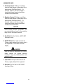
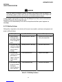
Throughout this manual, the words WARNING,
CAUTION, and NOTE may appear. Pay particular
attention to the information provided under these
headings. These special annotations are easily
recognized as follows:
WARNING
A WARNING gives information regarding
possible personal injury.
CAUTION
A CAUTION refers to possible equipment
damage.
NOTE
A NOTE offers helpful information concerning
certain operating procedures.
Electronic copies of this manual can also be
downloaded at no charge in Acrobat PDF format
by going to the Thermal Arc web site listed
below and clicking on the Literature Library link:
http://www.thermalarc.com
2.02 Equipment Identification
The unit’s identification number (specification or
part number), model, and serial number usually
appear on a nameplate attached to the control
panel. In some cases, the nameplate may be
attached to the rear panel. Equipment which
does not have a control panel such as gun and
cable assemblies is identified only by the
specification or part number printed on the
shipping container. Record these numbers on
the bottom of page i for future reference.
Additional copies of this manual may be purchased
by contacting Thermal Arc at the address and
phone number in your area listed in the inside back
cover of this manual. Include the Service Manual
number and equipment identification numbers.

ARCMASTER 160TS
14
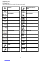
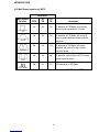
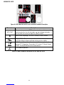
2.04 Symbol Chart
Note that only some of these symbols will appear on your model.
egarepmA
STICK (Shielded Metal Arc
SMAW)
egatloV
Pulse Current Function
Hertz (frequency)
Spot Time (GTAW)
SEC sdnoceS
Remote Control (Panel/Remote)
% tnecreP
Remote Function
DC (Direct Current)
Arc Control (SMAW)
AC (Alternating Current
Gas Post-Flow
Standard Function
Gas Pre-Flow
Slope Function VRD Voltage Reduction Device Circuit
Slope W/Repeat Function
Negative
Spot Function
Positive
Impulse Starting (High Frequency
GTAW)
Gas Input
Touch Start (Lift Start TIG circuit
GTAW)
Gas Output

ARCMASTER 160TS
15
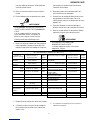
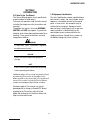
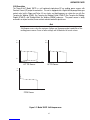
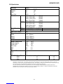
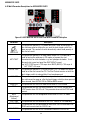
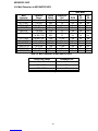
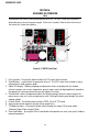
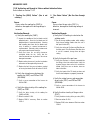
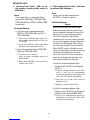
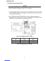
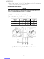
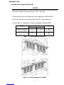
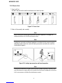
2.05 Description
The Thermal Arc™ Model 160TS is a self contained single-phase DC arc welding power sources with
Constant Current (CC) output characteristics. This unit is equipped with a Digital Volt/Amperage Meter, gas
control valve, built in Sloper and Pulser, lift arc starter, and high-frequency arc starter for use with Gas
Tungsten Arc Welding (GTAW), Gas Tungsten Arc Welding-Pulsed (GTAW-P) Gas Tungsten Arc Welding-
Sloped (GTAW-S), and Shielded Metal Arc Welding (SMAW) processes. The power source is totally
enclosed in an impact resistant, flame resistant and non-conductive plastic case.
Note
Volt-Ampere curves show the maximum Voltage and Amperage output capabilities of the
welding power source. Curves of other settings will fall between the curves shown
.
160A )A(A5
(V)
OCV
STICK Process
200A )A(A52
(V)
OCV
10V
160A (A)
(V)
OCV
5A
LIFT TIG Process HF TIG Process
Figure 2-1: Model 160TS Volt-Ampere curve

ARCMASTER 160TS
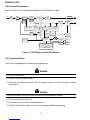
16
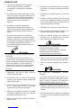
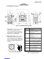
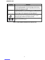
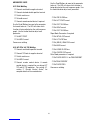
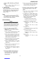
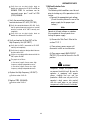
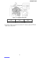
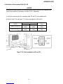
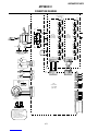
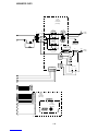
2.06 Functional Block Diagrams
Figure 2-2 illustrates the functional block diagram of the 160TS-power supply.
To each control circuit
Ma i n
Circuit
Switch Filter
Input
Diode Capacitor
DC Power
Primary
Voltage
Sensor
IGBT
Inverter
Themal
Detector
Ma i n
Transformers
(T 1)
Outp u t
Inductor
Outp u t
Diodes Transformer
(HCT 1 )
Hall Current
Lift Tig Mode
Output Short
Sensing
Circuit
Stick Mode
VRD
Sensing
Circuit
Thermal
Sensor
Circuit
Drive
Circuit
+/-12VDC +18VDC
+24VDC +5VDC
Trouble
Sensing
Circuit
T orc h Control
Connection
(CON1)
Current
Adjustment
Circuit
Reference
Adjustment &
Mode select Switch
Panel Circuit Boad
Sequence
Control Fan Control
Circuit Fan
Input
Power
Primary
Circuit
Sensor
Gas Co n trol
Circuit Solenoid
Coupling
Coil
High
Frequency
Unit
HF Unit
Control
Circuit
Figure 2-2: 160TS Model Functional Block Diagram
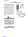
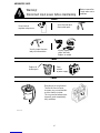
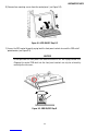
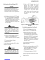
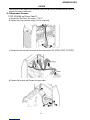
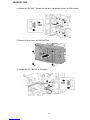
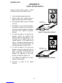
2.07 Transporting Methods
These units are equipped with a handle for carrying purposes.
WARNING
ELECTRIC SHOCK can kill.
DO NOT TOUCH live electrical parts.
Disconnect input power conductors from de-energized supply line before moving the welding
power source.
WARNING
FALLING EQUIPMENT can cause serious personal injury and equipment damage.
Lift unit with handle on top of case.
Use handcart or similar device of adequate capacity.
If using a fork lift vehicle, place and secure unit on a proper skid before transporting.
La page est en cours de chargement...
La page est en cours de chargement...
La page est en cours de chargement...
La page est en cours de chargement...
La page est en cours de chargement...
La page est en cours de chargement...
La page est en cours de chargement...
La page est en cours de chargement...
La page est en cours de chargement...
La page est en cours de chargement...
La page est en cours de chargement...
La page est en cours de chargement...
La page est en cours de chargement...
La page est en cours de chargement...
La page est en cours de chargement...
La page est en cours de chargement...
La page est en cours de chargement...
La page est en cours de chargement...
La page est en cours de chargement...
La page est en cours de chargement...
La page est en cours de chargement...
La page est en cours de chargement...
La page est en cours de chargement...
La page est en cours de chargement...
La page est en cours de chargement...
La page est en cours de chargement...
La page est en cours de chargement...
La page est en cours de chargement...
La page est en cours de chargement...
La page est en cours de chargement...
La page est en cours de chargement...
La page est en cours de chargement...
La page est en cours de chargement...
La page est en cours de chargement...
La page est en cours de chargement...
La page est en cours de chargement...
La page est en cours de chargement...
La page est en cours de chargement...
La page est en cours de chargement...
La page est en cours de chargement...
La page est en cours de chargement...
La page est en cours de chargement...
La page est en cours de chargement...
La page est en cours de chargement...
La page est en cours de chargement...
La page est en cours de chargement...
La page est en cours de chargement...
La page est en cours de chargement...
La page est en cours de chargement...
La page est en cours de chargement...
La page est en cours de chargement...
La page est en cours de chargement...
La page est en cours de chargement...
La page est en cours de chargement...
La page est en cours de chargement...
La page est en cours de chargement...
La page est en cours de chargement...
La page est en cours de chargement...
La page est en cours de chargement...
La page est en cours de chargement...
La page est en cours de chargement...
La page est en cours de chargement...
La page est en cours de chargement...
La page est en cours de chargement...
La page est en cours de chargement...
La page est en cours de chargement...
La page est en cours de chargement...
La page est en cours de chargement...
La page est en cours de chargement...
La page est en cours de chargement...
La page est en cours de chargement...
La page est en cours de chargement...
La page est en cours de chargement...
La page est en cours de chargement...
La page est en cours de chargement...
La page est en cours de chargement...
La page est en cours de chargement...
La page est en cours de chargement...
La page est en cours de chargement...
La page est en cours de chargement...
La page est en cours de chargement...
La page est en cours de chargement...
La page est en cours de chargement...
La page est en cours de chargement...
La page est en cours de chargement...
La page est en cours de chargement...
La page est en cours de chargement...
La page est en cours de chargement...
La page est en cours de chargement...
La page est en cours de chargement...
La page est en cours de chargement...
La page est en cours de chargement...
La page est en cours de chargement...
La page est en cours de chargement...
-
 1
1
-
 2
2
-
 3
3
-
 4
4
-
 5
5
-
 6
6
-
 7
7
-
 8
8
-
 9
9
-
 10
10
-
 11
11
-
 12
12
-
 13
13
-
 14
14
-
 15
15
-
 16
16
-
 17
17
-
 18
18
-
 19
19
-
 20
20
-
 21
21
-
 22
22
-
 23
23
-
 24
24
-
 25
25
-
 26
26
-
 27
27
-
 28
28
-
 29
29
-
 30
30
-
 31
31
-
 32
32
-
 33
33
-
 34
34
-
 35
35
-
 36
36
-
 37
37
-
 38
38
-
 39
39
-
 40
40
-
 41
41
-
 42
42
-
 43
43
-
 44
44
-
 45
45
-
 46
46
-
 47
47
-
 48
48
-
 49
49
-
 50
50
-
 51
51
-
 52
52
-
 53
53
-
 54
54
-
 55
55
-
 56
56
-
 57
57
-
 58
58
-
 59
59
-
 60
60
-
 61
61
-
 62
62
-
 63
63
-
 64
64
-
 65
65
-
 66
66
-
 67
67
-
 68
68
-
 69
69
-
 70
70
-
 71
71
-
 72
72
-
 73
73
-
 74
74
-
 75
75
-
 76
76
-
 77
77
-
 78
78
-
 79
79
-
 80
80
-
 81
81
-
 82
82
-
 83
83
-
 84
84
-
 85
85
-
 86
86
-
 87
87
-
 88
88
-
 89
89
-
 90
90
-
 91
91
-
 92
92
-
 93
93
-
 94
94
-
 95
95
-
 96
96
-
 97
97
-
 98
98
-
 99
99
-
 100
100
-
 101
101
-
 102
102
-
 103
103
-
 104
104
-
 105
105
-
 106
106
-
 107
107
-
 108
108
-
 109
109
-
 110
110
-
 111
111
-
 112
112
-
 113
113
-
 114
114


Thermal Arc 160 TS ARCMASTER Manuel utilisateur
- Catégorie
- Système de soudage
- Taper
- Manuel utilisateur
- Ce manuel convient également à
dans d''autres langues
Documents connexes
-
 Thermal Arc 160 TS ARCMASTER® Inverter Arc Welder Manuel utilisateur
-
 Thermal Arc 400 S ARCMASTER® Inverter Arc Welder Manuel utilisateur
-
 Thermal Arc 300 TS ARCMASTER® Inverter Arc Welder Manuel utilisateur
-
 Thermal Arc 200 ACDC ARCMASTER® Inverter Arc Welder Manuel utilisateur
-
 Thermal Arc 300 MST ARCMASTER® Inverter Arc Welder Manuel utilisateur
-
 Thermal Arc 400 MST ARCMASTER® Inverter Arc Welder Manuel utilisateur
-
 Thermal Arc 400 MSTP ARCMASTER® Inverter Arc Welder Manuel utilisateur
-
 Thermal Arc 300 TS ARCMASTER® Inverter Arc Welder Manuel utilisateur


