Bosch NGM5056UC 800 Series Gas Cooktop Manuel utilisateur
- Catégorie
- Cuisinières
- Taper
- Manuel utilisateur

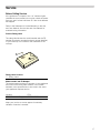
Installation Manual
Gas Cooktop
NGM5056UC, NGM5656UC, NGM8056UC, NGM8656UC,
NGMP056UC, NGMP656UC, NGM8046UC, NGM8646UC

2
Table of Contents
Use and care manual
9 Safety Definitions ..................................................... 3
IMPORTANT SAFETY INSTRUCTIONS ........................ 4
Gas Appliance Safety .......................................................... 4
................................................................................................. 5
Propane Gas Installation ..................................................... 5
Equipment and Usage Safety Requirements .................. 5
Appliance Handling Safety ................................................. 5
Safety Codes and Standards ............................................. 6
State of California Proposition 65 Warning: .................... 6
Electric Safety ....................................................................... 6
High Altitude Installation ..................................................... 6
Before You Begin .......................................................... 7
Tools and Parts Needed ..................................................... 7
Parts Included ....................................................................... 7
General Information ............................................................. 7
Preparation ............................................................................ 7
Installation Procedure .................................................. 9
Prepare the Countertop ...................................................... 9
Seal the Cooktop with Foam Tape ................................... 9
Install the Cooktop ............................................................ 10
Connect Gas Supply ........................................................ 10
Connect Electrical Supply ............................................... 11
Burner Cap and Burner Base Placement ..................... 11
Install Burner Grates ......................................................... 15
Check the Installation ....................................................... 16
Service ......................................................................... 17
Before Calling Service ..................................................... 17
4XHVWLRQV"
ZZZERVFKKRPHFRPXV
:HORRNIRUZDUGWRKHDULQJIURP\RX
7KLV%RVFK$SSOLDQFHLVPDGHE\
%6++RPH$SSOLDQFHV&RUSRUDWLRQ
0DLQ6WUHHW6XLWH
,UYLQH&$

3
9 Safety Definitions
Safety Defi nitions
9WARNING
This indicates that death or serious injuries may
occur as a result of non-observance of this warning.
9CAUTION
This indicates that minor or moderate injuries may
occur as a result of non-observance of this warning.
NOTICE: This indicates that damage to the appliance or
property may occur as a result of non-compliance with
this advisory.
Note: This alerts you to important information and/or
tips.

9IMPORTANT SAFETY INSTRUCTIONS
READ AND SAVE THESE INSTRUCTIONS
4
IMPORTANT SAFET Y I NS T RUCT I ONS REA D AND SAVE THESE INSTRUCTIONS
Gas Appliance Safety
²
'RQRWVWRUHRUXVHJDVROLQHRURWKHUIODPPDEOH
YDSRUVDQGOLTXLGVLQWKHYLFLQLW\RIWKLVRUDQ\
RWKHUDSSOLDQFH
²
:+$772'2,)<2860(//*$6
'RQRWWU\WROLJKWDQ\DSSOLDQFH
'RQRWWRXFKDQ\HOHFWULFDOVZLWFK
'RQRWXVHDQ\SKRQHLQ\RXUEXLOGLQJ
,PPHGLDWHO\FDOO\RXUJDVVXSSOLHUIURPD
QHLJKERU·VSKRQH)ROORZWKHJDVVXSSOLHU·V
LQVWUXFWLRQV
,I\RXFDQQRWUHDFK\RXUJDVVXSSOLHUFDOO
WKHILUHGHSDUWPHQW
²
,QVWDOODWLRQDQGVHUYLFHPXVWEHSHUIRUPHG
E\DTXDOLILHGLQVWDOOHUVHUYLFHDJHQF\RUWKH
JDVVXSSOLHU
:$51,1*,IWKHLQIRUPDWLRQLQWKHVHLQVWUXFWLRQV
LVQRWIROORZHGH[DFWO\DILUHRUH[SORVLRQPD\
UHVXOWFDXVLQJSURSHUW\GDPDJHSHUVRQDOLQMXU\
RUGHDWK

5
9IMPORTANT SAFETY INSTRUCTIONS
READ AND SAVE THESE INSTRUCTIONS
IMPORTANT: SAVE THESE INSTRUCTIONS FOR THE
LOCAL ELECTRICAL INSPECTOR’S USE.
INSTALLER: LEAVE THESE INSTRUCTIONS WITH THE
UNIT FOR THE OWNER.
OWNER: PLEASE RETAIN THESE INSTRUCTIONS FOR
FUTURE REFERENCE.
WARNING
When properly cared for, your new appliance has been
designed to be safe and reliable. Read all instructions
carefully before use. These precautions will reduce the
risk of burns, electric shock, fire and injury to persons.
When using kitchen appliances, basic safety precautions
must be followed including those in the following pages.
WARNING
Do not repair, replace or remove any part of the
appliance unless specifically recommended in the
manuals. Improper installation, service or maintenance
can cause injury or property damage. Refer to this
manual for guidance. All other servicing must be done by
an authorized service agency.
▯Install a gas shutoff valve near the appliance. It must
be easily accessible in an emergency.
▯Leak testing must be conducted by the installer
according to the instructions in this manual.
▯The appliance and its individual shutoff valve must be
disconnected from the gas supply piping system
during any pressure testing at pressures in excess of
1/2 psi (3.5 kPa).
▯The appliance must be isolated from the gas supply
piping system by closing its individual manual shutoff
valve during any pressure testing of the gas supply
piping system at test pressures equal to or less than
1/2 psi (3.5 kPa).
▯The minimum supply pressure must be 1” water
column above the manifold pressure printed on the
data plate.
▯The maximum supply pressure must not exceed 14.0
inches water column (34.9 Millibars).
▯For Massachusetts installations:
▯Installation must be performed by a qualified or
licensed contractor, plumber or gas fitter qualified
or licensed by the state, province or region where
this appliance is being installed.
▯Shut-off valve must be a “T” handle gas cock.
▯Flexible gas connector must be new and not longer
than 36 inches.
▯Installer-show the owner where the gas shut-off valve
is located.
Propane Gas Installation
▯The propane gas tank must be equipped with its own
high pressure regulator. In addition, the regulator
supplied with this unit must also be used.
▯The appliance is shipped from the factory for use with
natural gas. It must be converted for use with propane.
A qualified technician or installer must do the
conversion.
Equipment and Usage Safety
Requirements
▯The cooktop must be used in conjunction with a
suitable ventilation system.
▯Remove all tape and packaging before using the
appliance. Destroy the packaging after unpacking the
appliance. Never allow children to play with packaging
material.
▯Never modify or alter the construction of the
appliance. For example, do not remove panels, wire
covers or screws.
▯To eliminate the risk of burns or fire while reaching
over heated surface units, cabinet storage space
located above the surface units should be avoided. If
cabinet storage is to be provided, the risk can be
reduced by installing a hood that projects horizontally
a minimum of 5 inches beyond the bottom of the
cabinet.
▯Verify that cabinets above the cooktop are a maximum
of 13 inches (330mm) deep.
Appliance Handling Safety
CAUTION
▯Unit is heavy and requires at least two people
or proper equipment to move.
▯Hidden surfaces may have sharp edges. Use
caution when reaching behind or under
appliance.

9IMPORTANT SAFETY INSTRUCTIONS
READ AND SAVE THESE INSTRUCTIONS
6
Safety Codes and Standards
▯This appliance complies with one or more of the
following standards:
ANSI Z21.1- • CSA 1.1 Household Cooking Gas
Appliances
▯It is the responsibility of the owner and the installer to
determine if additional requirements and/or standards
apply to specific installations.
▯Installation must conform with local codes or, in the
absence of local codes, with the National Fuel Gas
Code, ANSI Z223.1/NFPA 54 or, in Canada, the
Natural Gas and Propane Installation Code, CSA
B149.1.
▯The appliance must be electrically grounded in
accordance with local codes or, in the absence of
local codes, with the National Electrical Code ANSI/
NFPA 70 or the Canadian Electric Code, CSA C22.1-
02.
State of California Proposition 65
Warning:
Electric Safety
▯Before you plug in an electrical cord, be sure all
controls are in the OFF position.
▯For appliances equipped with a cord and plug, do not
cut or remove the ground prong. It must be plugged
into a matching grounding type receptacle to avoid
electrical shock. If there is any doubt as to whether the
wall receptacle is properly grounded, the customer
should have it checked by a certified electrician.
▯This appliance should be installed in accordance with
the National Electric Code or Canadian Electrical
Code. It is required that the cooktop be installed on a
grounded, non-GFCI branch circuit.
▯Installer-show the owner the location of the circuit
breaker or fuse. Mark it for easy reference.
▯Before installing, turn power OFF at the service panel.
Lock service panel to prevent power from being turned
ON accidentally.
▯Be sure your appliance is properly installed and
grounded by a certified technician. Installation,
electrical connections and grounding must comply
with all applicable codes.
High Altitude Installation
Contact customer service for use at altitudes above
2,000 feet (610 meters).
This product may contain a chemical known to
the State of California, which can cause cancer
or reproductive harm. Therefore, the packaging
of your product may bear the following label as
required by California:

7
Before You Begin
Tools and Parts Needed
▯Phillips Head Screwdriver
▯Precision Flathead Screwdriver
▯Tape Measure
▯Teflon Tape (Gas Rated)
▯Adjustable Wrench or Channel Lock Pliers
Parts Included
▯Foam Tape
▯Mounting Brackets (4)
▯Screws, #10-32 x 2 1/2” (63.8 mm) (4)
▯Sheet Metal Screws, #8 x 3/8” (9.5 mm) (4)
▯Washers (4)
▯Burner Grates (3)
▯Burners
▯30” models: (4) or (5)
▯36” models: (5)
▯Burner Caps
▯30” models: (4) or (5)
▯36” models: (5)
▯Pressure Regulator
▯LP Gas Conversion Kit
Note: If parts are missing or damaged, call the number
or write to the address listed on the inside back cover.
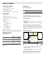
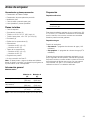
General Information
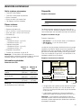
Overall Dimensions
Note: These are overall dimensions NOT cutout
dimensions.
Preparation
Electrical Requirements
9CAUTION
Do not use an extension cord with the gas cooktop.
This appliance requires a 60 Hz, 15 Amp, 120 VAC
connection. Plan the installation so that the power
connection is accessible from the front of the cabinet.
Gas Requirements
Supply Pressure:
▯Natural Gas: 7 inches water column (14.9 Millibars)
▯Propane Gas: 11 inches water column (27.4 Millibars)
The propane gas tank must be equipped with its own
high pressure regulator in addition to the pressure
regulator supplied with this unit. The cooktop is shipped
from the factory for use with natural gas. For use with LP
conversion, a certified technician or installer must do the
conversion.
Cabinet Requirements
▯Instructions are based on standard American cabinets
36” high (91cm) x 24” deep (61cm) with a 25”
(63cm) countertop.
▯The maximum depth of a cabinet installed above the
cooktop is 13” (33cm).
Note: All measurements given must be precisely
followed. If nonstandard cabinets are used, make sure
they are installed with minimum dimensions shown.
30” Models 36” Models
Width (Side to Side) 31”
(788 mm)
37”
(940 mm)
Depth (Front to Back) 21 1/4”
(540 mm)
21 1/4”
(540 mm)
Height (Top to Bottom) 3 13/16”
(97 mm)
3 13/16”
(97 mm)
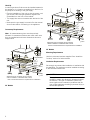
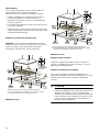
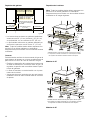
'HSWKIURP%DFN:DOO
&DELQHWPD[
&HQWHUHGRYHUFRRNWRS
5HDUZDOOPP 5LJKW6LGH
PLQ
/HIW6LGH
PLQ
PLQ
1*0PLQ
1*0PLQ
PP
$ERYHFRXQWHUPLQ
WRFRPEXVWLEOHVXUIDFH

8
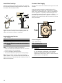
Hook Up
A manual gas shut-off valve must be installed external to
the appliance, in a location accessible from the front, for
the purpose of shutting of the gas supply.
▯Plan the installation of the unit so that the power cord,
gas shut-off valve and gas pressure regulator are
accessible from the front of the cabinet.
▯The supply line must not interfere with the back of the
unit.
▯Make sure the gas supply is turned off at the manual
shut-off valve before connecting to the appliance.
Countertop Requirements
Note: All measurements given must be precisely
followed. If nonstandard cabinets are used, make sure
they are installed with minimum dimensions shown in
image below.
30” Models
36” Models
Mounting Requirements
Use the hold down brackets supplied. See “Install the
Cooktop” section for further details.
Ventilation Requirements
We strongly recommend the installation of ventilation with
the appliance. The appliance must be installed according
to the furnished instructions.
9CAUTION
The appliance should not be installed with a
ventilation system that blows air downward toward
the burners. This type of ventilation system may
cause ignition and combustion problems with the
gas cooking appliance resulting in personal injury or
unintended operation.
PP
'LPHQVLRQIURPFRXQWHUWRSWRWRSRIJUDWHV
:KHQLQVWDOOHGLQFRPELQDWLRQZLWKDKRRG
UHIHUWRKRRGPDQXIDFWXUHU¶VUHTXLUHPHQWVIRULQVWDOODWLRQ
JDV
FRQQHFWLRQ
ʎʓʘ´
PP
JDV
FRQQHFWLRQ
'LPHQVLRQIURPFRXQWHUWRSWRWRSRIJUDWHV
:KHQLQVWDOOHGLQFRPELQDWLRQZLWKDKRRG
UHIHUWRKRRGPDQXIDFWXUHU¶VUHTXLUHPHQWVIRULQVWDOODWLRQ
ʎʓʘ´

9
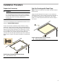
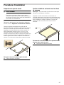
Installation Procedure
Installation Procedure
Prepare the Countertop
9WARNING
To avoid electrical shock hazard, before installing
the cooktop, switch power off at the service panel to
prevent the power from being switched on
accidentally.
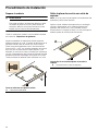
Cut out the countertop per the dimensions shown in the
section “Cabinet Requirements”.
Some solid surface materials require different cutting
methods. Consult with the solid surface manufacturer for
the correct cutting method needed. Apply heat reflective
tape such as Scotch Aluminum Foil Tape #425 or #427
(not included) around the cutout so that it folds over the
top and sides. Do not wrap the tape underneath the
cooktop. Be sure the tape extends beyond the outermost
flange of the cooktop. All corners should be covered with
tape.
Solid Surface Countertops-Counter Cutout
Seal the Cooktop with Foam Tape
Note: Failure to install the foam tape may affect burner
performance.
Apply the self adhesive foam tape in one continuous
rectangle directly to the counter around the perimeter of
the cutout as shown by the dotted line in the image
below. The foam tape should be flush with the edge of
the cutout.
Foam Tape Placement-Counter Cutout
AHeat Reflective Tape
$
AFoam Tape Placement
$

10
Install the Cooktop
Insert the cooktop into the cutout. Attach the clamps of
the mounting brackets packaged with the cooktop. Use
the washer and screws provided.
Adjust the mounting brackets to desired position and
tighten screws to cooktop. Insert adjusting screw into
clamp and secure cooktop to countertop.
Attaching Mounting Brackets
Note: For solid surface material installations:
▯Insert a wooden block between the end of the screw
and the bottom of the countertop.
▯Do not overtighten adjusting screw.
▯Trim excess aluminum tape around cooktop flange.
Tip: Install hold down bracket without the adjusting
screw installed. Turn hold down brackets flush with the
sides of the cutout. This will help with inserting cooktop in
hard-to-reach spaces.
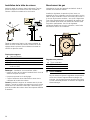
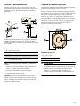
Connect Gas Supply
The gas inlet to the unit is located at the right rear of the
cooktop.
Install the pressure regulator (supplied with unit) to
manifold pipe using Teflon tape on threads of manifold
pipe. Turn to hand tighten plus 1/4 turn, not exceeding 1
turn for alignment. To prevent possible damage to the
gas pressure regulator, install it after the cooktop is in its
permanent position. When the regulator is securely
installed on the manifold pipe, the conversion nut will be
easily accessible.
Pressure Regulator
9WARNING
Do not attempt any adjustment of the pressure
regulator, except when converting to propane.
Adjustments could lead to leaks or cause incorrect
gas pressure to the appliance.
ACooktop
B/H Hold Down Bracket
C/E Adjusting Screw
DFoam Tape (Seal)
GWooden Block (to be used with solid surfacing
material)
$
%*
(
+
'
&
AManifold Pipe
BConversion Nut
CPressure Regulator
$
%&

11
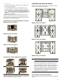
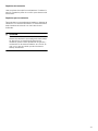
Side View Gas Cooktop Installation
Gas and Electrical Location
Connect the gas supply line to the unit pressure
regulator using a 1/2” flex gas line connector between
manual shut-off valve and pressure regulator. Always use
a new flex line.
Check supply line connections for leaks using a soap
solution or non-corrosive leak detection fluid. Do not use
a flame of any sort.
1.
Turn on gas.
2.
Apply a soap solution or non-corrosive leak detection
fluid to all joints and fittings in the gas connection
between the shut-off valve and the cooktop. Include
gas fittings and joints in the cooktop if connections
may have been disturbed during installation. Bubbles
appearing around fittings and connections indicate a
leak.
3.
If a leak appears, turn off supply line gas shut-off valve
and tighten connections.
4.
Retest for leaks by turning on the supply line gas shut-
off valve. When leak check is complete (no bubbles
appear), test is complete.
5.
Wipe off all soap solution or detection fluid residue.
Important Notes for Gas Connection:
▯The appliance and its individual gas shutoff valve must
be disconnected from the gas supply piping system
during any pressure testing of that system at test
pressures in excess of 1/2 psi (3.5kPa).
▯The appliance must be isolated from the gas supply
piping system by closing its individual manual shut-off
valve during any pressure testing of the gas supply
piping system at test pressures equal to or less than
1/2 psi (3.5kPa).
Connect Electrical Supply
Before connecting the 5-foot (1.5m) supply cord to a wall
receptacle, make certain that gas shut-off valve and all
burner controls are in OFF position.
Burner Cap and Burner Base Placement
9WARNING
To prevent flare-ups, do not use the cooktop without
all burner caps and all burner grates properly
positioned.
9WARNING
To prevent burns, do not touch burner caps or
grates while hot. Turn the cooktop off and allow the
entire cooktop to cool.
ARough-in Cooktop Box
BArrow on Pressure Regulator
CPressure Regulator
D1/2” Female Pipe Threads
EFlexible Gas Line
GPower Cord (60 inches/1,524mm)
H120 Volt Receptacle
JGas Cut-off Valve
KGas Supply Line Stub-out
LFloor
%$
%
&
(
'
*
+
-
/.
$UURZRQWKHEDFNRI
WKHSUHVVXUHUHJXODWRU
VKRZVWKHGLUHFWLRQRI
JDVIORZ

12
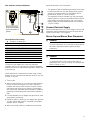
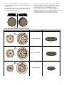
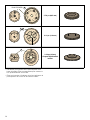
The burner caps must be properly placed for the cooktop
to function properly. If the burner cap is not properly
placed, one or more of the following problems may
occur:
▯Burner flames are too high.
▯Burner flames extend too far on sides.
▯Stainless steel discolors.
▯Burners do not ignite.
▯Burner flames light unevenly.
▯Burner emits gas odor.
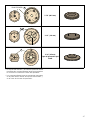
Correct Burner Cap Placement
Incorrect Burner Cap Placement
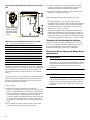
Burner Base and Burner Cap Placement
▯After electrical connection is complete, place each
burner base on the corresponding location on the
cooktop.
▯Pay special attention to avoid damaging the igniter
during installation of the base.
▯The small hole or cutout near the edge should also
line up with the igniter.
▯Once each burner base is located and resting evenly,
place each burner cap on its correct burner base.
AIgniter
BBurner Cap
CBurner Base
DJet Holder
EPanhead Screw
%
&
$'
(

13
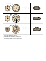
▯Place burner cap gently on top of base so that the
prongs of the burner base fit snugly into the groove of
the burner cap.
▯Make sure the cap is centered on the burner base and
lies flat and that there is no gap between the burner
base and the burner cap.
▯Gently try to move the burner cap from side to side to
check for proper placement. If placement is correct,
the cap will click from side to side as the prongs hit
the grooved ridge on the underside of the cap.
▯If the maintop is removed by a certified installer (for
example to check electrical or piping connection) the
panhead screws that were removed must be re-
installed to ensure proper functionality of burners.
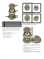
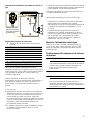
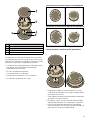
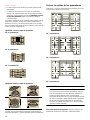
Correct Placement for Burner Base and Burner Cap
Corresponding Jet Holder and Burner Base Burner Cap Dimensions Corresponding Burner Cap
3 15/16” (100 mm)
2 15/16” (75 mm)
2 3/16” (55 mm)
5
5
5
65
65
65
$
$
$

14
▯The jet holder and the burner base have
corresponding letter demarcations to ensure proper
placement of the burner base.
▯The corresponding letters can be found on the inside
bottom of the jet holder and on the bottom of the
burner base.
3 7/8” (98.5 mm)
4 1/2” (116 mm)
3 3/4” (95 mm)
OptiSim® Burner Cap
'8$/67$&.('
'8$/67$&.('
±
'
8
$
/
6
7
$
&
.
(
'
±
%
8
5
1
(
5
'6
5
85
5
85
$
$
$

15
<notes> NoLang
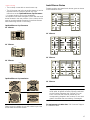
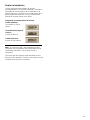
▯The cooktop comes with an extra burner cap.
▯The A/A burner cap is for an auxilary burner. It can be
replaced with the OptiSim® burner cap. See
instructions under OptiSim® Burner Cap Placement
for proper location and correct installation.
The OptiSim® has been designed to work with the small
burner located in the rear position of the cooktop and is
used to provide optimal simmering for delicate sauces
while minimizing the risk of scorching.
OptiSim® Burner Cap Placement
30” 4 Burner
30” 5 Burner
36” 5 Burner
OptiSim® Burner Cap Installation
When properly installed the cap will extend beyond the
burner base and raised surface.
Install Burner Grates
Properly position and install each burner grate as shown
in the illustration below.
30” 4 Burner
30” 5 Burner
36” 5 Burner
9WARNING
To prevent flare-ups, properly support pots and
avoid spills, all grates must be properly positioned
on the cooktop whenever the cooktop is in use.
Each of the four feet must be placed into the
corresponding dimples in the cooktop. Do not use a
grate if the rubber feet are missing or damaged.
For replacement of rubber feet: Call Customer Support
at 1-800-944-2904.
237,6,0
237,6,0
237,6,0

16
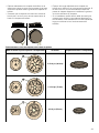
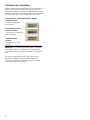
Check the Installation
Place each correct sized burner cap in its seated,
notched position and check the operation of the electric
igniters. Check flame characteristics. Flame should be
blue with a minimal yellow tip on the outer cone of the
flames.
Checking Flame Characteristics
Note: If the flame is completely or mostly yellow, verify
that the regulator is set for the correct fuel. After
adjustment, retest.
Some yellow streaking is normal during the initial start-
up. Allow unit to operate 4-5 minutes and re-evaluate
before making adjustments.
Yellow Flames:
Further adjustment is
required.
Yellow Tips on Outer
Cones:
Normal for LP Gas
Soft Blue Flames:
Normal for Natural Gas

17
Service
Before Calling Service
If the igniters do not spark or the “on” indicator lights
(available in some models) do not glow, check the power
source to see if a fuse has blown or if the circuit breaker
has tripped.
Refer to the Statement of Limited Warranty in the Use
and Care Manual. See the Use and Care Manual for
troubleshooting information.
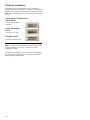
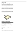
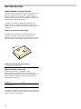
Product Rating Label
The rating label shows the model number and the FD
number (production number/product’s unique identifier)
of your cooktop. It is located on the underside of the
cooktop.
Rating Label Location
Model number and FD Number
The model number and the FD number of your appliance
are found on the rating label. Make a note of these
numbers in the space below to save time in the event
your appliance requires service.
Keep your invoice or escrow papers for warranty
validation if service is needed.
A Rating Label
Model # FD #
Bosch Customer Support 800-944-2904
$

18
Table des Matières
Notice d’uti lisati on
9 Définitions de sécurité ........................................... 19
IMPORTANTES CONSIGNES DE SÉCURITÉ ............. 20
Utilisation sécuritaire de l'électroménager
alimenté au gaz : ............................................................... 20
.............................................................................................. 21
Installation au gaz propane ............................................. 21
Exigences en matière de sécurité pour
l'utilisation et l'équipement ............................................... 21
Sécurité de manutention des appareils ........................ 22
Codes et normes de sécurité ......................................... 22
Avertissement issue de la proposition 65 de
l’État de la Californie : ...................................................... 22
Sécurité électrique ............................................................ 22
Installation à altitude élevée ............................................ 22
Avant de commencer .................................................. 23
Outils et pièces nécessaires ........................................... 23
Pièces incluses .................................................................. 23
Informations générales .................................................... 23
Préparatifs .......................................................................... 23
Procédure d'installation ............................................. 25
Préparation du plan de travail ........................................ 25
Sceller la table de cuisson avec le ruban
de mousse .......................................................................... 25
Installation de la table de cuisson ................................. 26
Branchement du gaz ........................................................ 26
Brancher l'alimentation électrique .................................. 27
Positionnement du chapeau et de la base
du brûleur ........................................................................... 27
Installation des grilles du brûleur ................................... 31
Vérification de l'installation .............................................. 32
Dépannage ................................................................... 33
Avant d'appeler le service de dépannage ................... 33
9RXVDYH]GHVTXHVWLRQV"
ZZZERVFKKRPHFRPXV
ââ
1RXVQRXVIHURQVXQSODLVLUGHYRXVVHUYLU
&HWDSSDUHLOpOHFWURPpQDJHU%RVFKHVWIDEULTXpSDU
%6++RPH$SSOLDQFHV&RUSRUDWLRQ
0DLQ6WUHHW6XLWH
,UYLQH&$

19
9 Définitions de sécurité
Définitions de sécurité
9AVERTISSEMENT
Ceci indique que le non-respect de cet
avertissement peut entraîner des blessures graves,
voire la mort.
9ATTENTION
Ceci indique que le non-respect de cet
avertissement peut entraîner des blessures légères
ou de gravité moyenne.
AVIS : Ceci indique que la non-conformité à cet avis de
sécurité peut entraîner des dégâts matériels ou
endommager l'appareil.
Remarque : Ceci vous signale des informations et/ou
indications importantes.

9IMPORTANTES CONSIGNES DE SÉCURITÉ
LIRE ET CONSERVER CES INSTRUCTIONS
20
IMPORTANTES CONSI GNES DE S ÉCURI TÉ LI RE ET CONSE RV E R CE S INSTRUCTIONS
Utilisation sécuritaire de l'électroménager alimenté au gaz :
²
1HSDVFRQVHUYHURXXWLOLVHUGHOHVVHQFHRX
GDXWUHVOLTXLGHVRXYDSHXUVLQIODPPDEOHVj
SUR[LPLWpGHFHWDSSDUHLORXGHWRXWDXWUHDSSDUHLO
²
48()$,5(6,92863(5&(9(=81(2'(85'(*$=
1HSDVHVVD\HUGHPHWWUHXQDSSDUHLOVRXVWHQVLRQ
1HSDVWRXFKHUGLQWHUUXSWHXUGHFRXUDQWpOHFWULTXH
1HSDVXWLOLVHUGHWpOpSKRQHVGDQVOpGLILFH
&RPPXQLTXHULPPpGLDWHPHQWDYHFOHIRXUQLVVHXU
GHJD]GHSXLVODSSDUHLOWpOpSKRQLTXHGXQYRLVLQ
5HVSHFWHUOHVGLUHFWLYHVGXIRXUQLVVHXUGHJD]
6LOVDYqUHLPSRVVLEOHGHMRLQGUHOHIRXUQLVVHXUGH
JD]FRPPXQLTXHUDYHFOHVSRPSLHUV
²
8WLOLVHUOHVVHUYLFHVGXQLQVWDOODWHXURXGXQHDJHQFH
GHVHUYLFHVTXDOLILpVRXOHIRXUQLVVHXUGHJD]SRXU
SURFpGHUjOLQVWDOODWLRQHWDX[UpSDUDWLRQV
$9(57,66(0(176LOHVGLUHFWLYHVQHVRQWSDV
VXLYLHVjODOHWWUHLO\DXQULVTXHGLQFHQGLHRX
GH[SORVLRQSRXYDQWHQWUDvQHUGHVGRPPDJHV
PDWpULDX[GHVEOHVVXUHVRXXQGpFqV
La page charge ...
La page charge ...
La page charge ...
La page charge ...
La page charge ...
La page charge ...
La page charge ...
La page charge ...
La page charge ...
La page charge ...
La page charge ...
La page charge ...
La page charge ...
La page charge ...
La page charge ...
La page charge ...
La page charge ...
La page charge ...
La page charge ...
La page charge ...
La page charge ...
La page charge ...
La page charge ...
La page charge ...
La page charge ...
La page charge ...
La page charge ...
La page charge ...
La page charge ...
La page charge ...
La page charge ...
La page charge ...
-
 1
1
-
 2
2
-
 3
3
-
 4
4
-
 5
5
-
 6
6
-
 7
7
-
 8
8
-
 9
9
-
 10
10
-
 11
11
-
 12
12
-
 13
13
-
 14
14
-
 15
15
-
 16
16
-
 17
17
-
 18
18
-
 19
19
-
 20
20
-
 21
21
-
 22
22
-
 23
23
-
 24
24
-
 25
25
-
 26
26
-
 27
27
-
 28
28
-
 29
29
-
 30
30
-
 31
31
-
 32
32
-
 33
33
-
 34
34
-
 35
35
-
 36
36
-
 37
37
-
 38
38
-
 39
39
-
 40
40
-
 41
41
-
 42
42
-
 43
43
-
 44
44
-
 45
45
-
 46
46
-
 47
47
-
 48
48
-
 49
49
-
 50
50
-
 51
51
-
 52
52


Bosch NGM5056UC 800 Series Gas Cooktop Manuel utilisateur
- Catégorie
- Cuisinières
- Taper
- Manuel utilisateur