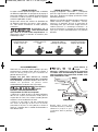
Bosch GBH2-28L-RT Mode d'emploi
- Catégorie
- Outils électroportatifs
- Taper
- Mode d'emploi
Ce manuel convient également à

GBH2-28L
Operating/Safety Instructions
Consignes d’utilisation/de sécurité
Instrucciones de funcionamiento y seguridad
For English Version
See page 2
Version française
Voir page 13
Versión en español
Ver la página 24
Call Toll Free for Consumer Information & Service Locations
Pour obtenir des informations et les adresses de nos centres de service après-vente, appelez ce numéro gratuit
Llame gratis para obtener información para el consumidor y ubicaciones de servicio
1-877-BOSCH99 (1-877-267-2499) www.boschtools.com
IMPORTANT
Read Before Using
IMPORTANT
Lire avant usage
IMPORTANTE
Leer antes de usar
2610047986_GBH2-28L 10/2/17 1:46 PM Page 1

-2-
Work area safety
Keep work area clean and well lit. Cluttered
or dark areas invite accidents.
Do not operate power tools in explosive
atmospheres, such as in the presence of
flammable liquids, gases or dust. Power
tools create sparks which may ignite the dust
or fumes.
Keep children and bystanders away while
operating a power tool. Distractions can
cause you to lose control.
Electrical safety
Power tool plugs must match the outlet.
Never modify the plug in any way. Do not
use any adapter plugs with earthed
(grounded) power tools. Unmodified plugs
and matching outlets will reduce risk of
electric shock.
Avoid body contact with earthed or grounded
surfaces such as pipes, radiators, ranges
and refrigerators. There is an increased risk
of electric shock if your body is earthed or
grounded.
Do not expose power tools to rain or wet
conditions. Water entering a power tool will
increase the risk of electric shock.
Do not abuse the cord. Never use the cord
for carrying, pulling or unplugging the power
tool. Keep cord away from heat, oil, sharp
edges or moving parts. Damaged or entangled
cords increase the risk of electric shock.
When operating a power tool outdoors,
use an extension cord suitable for outdoor
use. Use of a cord suitable for outdoor use
reduces the risk of electric shock.
If operating a power tool in a damp location
is unavoidable, use a Ground Fault Circuit
Interrupter (GFCI) protected supply. Use of
an GFCI reduces the risk of electric shock.
Personal safety
Stay alert, watch what you are doing and
use common sense when operating a
power tool. Do not use a power tool while
you are tired or under the influence of drugs,
alcohol or medication. A moment of inattention
while operating power tools may result in
serious personal injury.
Read all safety warnings and all instructions. Failure to follow the
warnings and instructions may result in electric shock, fire and/or serious
injury.
SAVE ALL WARNINGS AND INSTRUCTIONS FOR FUTURE REFERENCE
The term “power tool” in the warnings refers to your mains-operated (corded) power tool or
battery-operated (cordless) power tool.
General Power Tool Safety Warnings
Safety Symbols
The definitions below describe the level of severity for each signal word. Please read the manual
and pay attention to these symbols.
!
This is the safety alert symbol. It is used to alert you to potential
personal injury hazards. Obey all safety messages that follow this
symbol to avoid possible injury or death.
DANGER indicates a hazardous situation which, if not avoided, will
result in death or serious injury.
WARNING indicates a hazardous situation which, if not avoided, could
result in death or serious injury.
CAUTION, used with the safety alert symbol, indicates a hazardous
situation which, if not avoided, will result in minor or moderate injury.
2610047986_GBH2-28L 10/2/17 1:46 PM Page 2

-3-
Wear ear protectors. Exposure to noise can
cause hearing loss.
Use auxiliary handle(s), if supplied with the
tool. Loss of control can cause personal injury.
Hold power tools by insulated gripping
surfaces, when performing an operation
where the cutting tool may contact hidden
wiring or its own cord. Cutting accessory
contacting a "live" wire may make exposed
metal parts of the power tool "live" and could
give the operator an electric shock.
Use clamps or another practical way to
secure and support the workpiece to a
stable platform. Holding the work by hand
or against your body leaves it unstable and
may lead to loss of control.
Do not drill, fasten or break into existing
walls or other blind areas where electrical
wiring may exist. If this situation is
unavoidable, disconnect all fuses or circuit
breakers feeding this worksite.
Use a metal detector to determine if there
are gas or water pipes hidden in the work
area or call the local utility company for
assistance before beginning the
operation. Striking or cutting into a gas line
U
se personal protective equipment. Always
wear eye protection. Protective equipment
such as dust mask, non-skid safety shoes, hard
hat, or hearing protection used for appropriate
conditions will reduce personal injuries.
Prevent unintentional starting. Ensure the
switch is in the off-position before
connecting to power source and / or battery
pack, picking up or carrying the tool.
Carrying power tools with your finger on the
switch or energizing power tools that have the
switch on invites accidents.
Remove any adjusting key or wrench before
turning the power tool on. A wrench or a
key left attached to a rotating part of the power
tool may result in personal injury.
Do not overreach. Keep proper footing and
balance at all times. This enables better
control of the power tool in unexpected
situations.
Dress properly. Do not wear loose clothing
or jewelry. Keep your hair, clothing and
gloves away from moving parts. Loose
clothes, jewelry or long hair can be caught in
moving parts.
If devices are provided for the connection
of dust extraction and collection facilities,
ensure these are connected and properly
used. Use of dust collection can reduce dust-
related hazards.
Power tool use and care
Do not force the power tool. Use the
correct power tool for your application. The
correct power tool will do the job better and
safer at the rate for which it was designed.
Do not use the power tool if the switch does
n
ot turn it on and off. Any power tool that
cannot be controlled with the switch is
dangerous and must be repaired.
Disconnect the plug from the power source
and/or the battery pack from the power tool
before making any adjustments, changing
accessories, or storing power tools. Such
preventive safety measures reduce the risk of
starting the power tool accidentally.
Store idle power tools out of the reach of
children and do not allow persons unfamiliar
with the power tool or these instructions to
operate the power tool. Power tools are
dangerous in the hands of untrained users.
Maintain power tools. Check for misalignment
or binding of moving parts, breakage of
parts and any other condition that may
affect the power tool’s operation. If damaged,
have the power tool repaired before use.
Many accidents are caused by poorly
maintained power tools.
Keep cutting tools sharp and clean. Properly
maintained cutting tools with sharp cutting
edges are less likely to bind and are easier to
control.
Use the power tool, accessories and tool
bits etc. in accordance with these instructions,
taking into account the working conditions
and the work to be performed. Use of the
power tool for operations different from those
intended could result in a hazardous situation.
Service
Have your power tool serviced by a qualified
repair person using only identical
replacement parts. This will ensure that the
safety of the power tool is maintained.
Rotary Hammer Safety Rules
2610047986_GBH2-28L 10/2/17 1:46 PM Page 3

GFCI and personal protection devices like
electrician’s rubber gloves and footwear will
further enhance your personal safety.
Do not use AC only rated tools with a DC
power supply. While the tool may appear to
work, the electrical components of the AC
rated tool are likely to fail and create a hazard
to the operator.
Keep handles dry, clean and free from oil
and grease. Slippery hands cannot safely
control the power tool.
Develop a periodic maintenance schedule
for your tool. When cleaning a tool be
careful not to disassemble any portion of
the tool since internal wires may be
misplaced or pinched or safety guard return
springs may be improperly mounted.
Certain cleaning agents such as gasoline,
carbon tetrachloride, ammonia, etc. may
damage plastic parts.
Risk of injury to user. The power cord must only
be serviced by a Bosch Factory Service Center
or Autho rized Bosch Service Station.
Some dust created by
power sanding, sawing,
grinding, drilling, and other construction
activities contains chemicals known to
cause cancer, birth defects or other
reproductive harm. Some examples of
these chemicals are:
• Lead from lead-based paints,
• Crystalline silica from bricks and cement and
other masonry products, and
• Arsenic and chromium from chemically-
treated lumber.
Your risk from these exposures varies,
depending on how often you do this type of
work. To reduce your exposure to these
chemicals: work in a well ventilated area, and
work with approved safety equipment, such as
those dust masks that are specially designed
to filter out microscopic particles.
Additional Safety Warnings
w
ill result in explosion. Water entering an
electrical device may cause electrocution.
Always use the side handle for maximum
control over torque reaction or kick-back.
Never attempt to operate this tool with
one hand. The slip clutch engages if you
firmly control the tool during a torque reaction
or kickback.
Always wear safety goggles or eye
protection when using this tool. Use a
dust mask or respirator for applications
that generate dust. Safety goggles or eye
protection will help deflect fragments of the
material that may be thrown toward your face
and eyes. Dust generated or gases released
from the material you are cutting (i.e.
asbestos insulated pipes, radon) may cause
respiratory difficulties.
Use thick cushioned gloves and limit the
exposure time by taking frequent rest
periods. Vibration caused by hammer-drill
action may be harmful to your hands and
arms.
Position the cord clear of rotating bit. Do
not wrap the cord around your arm or
wrist. If cord becomes entangled with the
s
pinning bit it could entrap you causing
serious personal injury.
Position yourself to avoid being caught
between the tool or side handle and walls
or posts. Should the bit become bound or
jammed in the work, the reaction torque of
the tool could crush your hand or leg.
Do not strike the bit with a handheld
hammer or sledgehammer when
attempting to dislodge a bound or
jammed bit. Fragments of metal from the bit
could dislodge and strike you or bystanders.
Never place the tool down until the bit or
accessory has come to a complete stop.
Do not use dull or damaged bits and
accessories. Dull or damaged bits have a
greater tendency to bind in the workpiece.
When removing the bit from the tool avoid
contact with skin and use proper
protective gloves when grasping the bit or
accessory. Accessories may be hot after
prolonged use.
Do not run the tool while carrying it at
your side. A spinning bit could become
entangled with clothing and injury may result.
-4-
2610047986_GBH2-28L 10/2/17 1:46 PM Page 4

-5-
IMPORTANT: Some of the following symbols may be used on your tool. Please study them
and learn their meaning. Proper interpretation of these symbols will allow you to operate the
tool better and safer.
Symbols
Symbol Designation / Explanation
V Volts (voltage)
A Amperes (current)
Hz Hertz (frequency, cycles per second)
W Watt (power)
kg Kilograms (weight)
min Minutes (time)
s Seconds (time)
Diameter (size of drill bits, grinding wheels, etc.)
n
0
No load speed (rotational speed at no load)
n Rated speed (maximum attainable speed)
.../min
Revolutions or reciprocation per minute (revolutions, strokes, surface speed,
orbits etc. per minute)
0 Off position (zero speed, zero torque...)
1, 2, 3, ...
I, II, III,
Selector settings (speed, torque or position settings. Higher number means
greater speed)
0
Infinitely variable selector with off (speed is increasing from 0 setting)
Arrow (action in the direction of arrow)
Alternating current (type or a characteristic of current)
Direct current (type or a characteristic of current)
Alternating or direct current (type or a characteristic of current)
Class II construction (designates double insulated construction tools)
Earthing terminal (grounding terminal)
2610047986_GBH2-28L 10/2/17 1:46 PM Page 5

-6-
Symbols (continued)
IMPORTANT: Some of the following symbols may be used on your tool. Please study them
and learn their meaning. Proper interpretation of these symbols will allow you to operate the
tool better and safer.
Symbol Designation / Explanation
Designates Li-ion battery recycling program
Designates Ni-Cad battery recycling program
Alerts user to read manual
Alerts user to wear eye protection
This symbol designates that this tool is listed by Underwriters Laboratories.
This symbol designates that this component is recognized by Underwriters
Laboratories.
This symbol designates that this tool is listed by Underwriters Laboratories,
to United States and Canadian Standards.
This symbol designates that this tool is listed by the Canadian Standards
Association.
This symbol designates that this tool is listed by the Canadian Standards
Association, to United States and Canadian Standards.
This symbol designates that this tool is listed by the Intertek Testing
Services, to United States and Canadian Standards.
This symbol designates that this tool complies to NOM Mexican Standards.
2610047986_GBH2-28L 10/2/17 1:46 PM Page 6

-7-
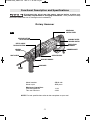
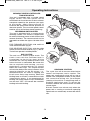
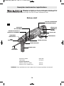
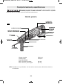
Functional Description and Specifications
Disconnect the plug from the power source before making any
assembly, adjustments or changing accessories. Such preventive safety
measures reduce the risk of starting the tool accidentally.
Rotary Hammer
FIG. 1
HAMMERHOOK
™
REVERSING
SWITCH LEVER
VARIABLE SPEED
TRIGGER SWITCH
VENTILATION
OPENINGS
RELEASE BUTTON
SELECTOR DIAL
DEPTH GAUGE
RELEASE BUTTON
LOCKING
SLEEVE
DUST SHIELD
DEPTH
GAUGE
SELECTOR DIAL
AUXILIARY HANDLE
HAND GRIP
Model number GBH2-28L
Shank style SDS-plus
®
Maximum Capacities:
Carbide tipped bits 1-1/8"
Thin wall core bits 2-5/8"
NOTE: For tool specifications refer to the nameplate on your tool.
2610047986_GBH2-28L 10/2/17 1:46 PM Page 7

Disconnect the plug from
the power source before
making any assembly, adjustments or
changing accessories. Such preventive
safety measures reduce the risk of starting the
tool accidentally.
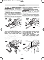
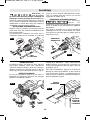
INSTALLING SDS-plus
®
ACCESSORIES
Clean the insert shank end of the accessory to
remove any debris, then lightly grease with a
light oil or lubricant.
Insert accessory into the chuck through the
dust shield, while twisting and pushing inward
until it locks automatically into place. Pull
outward on the accessory to be certain it is
locked into the chuck (Fig. 2).
REMOVING SDS-plus
®
ACCESSORIES
Accessories may be hot
after use. Avoid contact
with skin and use proper protective gloves or
cloth to remove.
To remove an accessory, pull locking sleeve
backward and pull bit forward. All accessories
should be wiped clean after removing (Fig. 3).
-8-
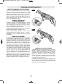
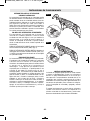
AUXILIARY HANDLE
The tool must be supported with the auxiliary
handle, which can be swiveled 360˚. To
reposition and/or swivel the handle, loosen
the hand grip, move the handle to the
desired position along the barrel and
securely retighten the hand grip (Fig. 4).
DEPTH GAUGE
Your drilling depth can be pre-set and/or
repeated by using the depth gauge.
Setting depth: After the auxiliary handle is
installed, make sure the accessory has been
fully inserted into the tool holder before
setting the depth gauge (Fig. 5).
To adjust depth, push the depth gauge
release button, slide the depth gauge to
desired depth and release pressure on
button to lock the depth gauge in place.
Assembly
1
2
3
DUST
SHIELD
FIG. 2
2
1
LOCKING
SLEEVE
FIG. 3
2
1
3
HAND
GRIP
FIG. 4
X
DEPTH
GAUGE
RELEASE
BUTTON
DEPTH
GAUGE
FIG. 5
2610047986_GBH2-28L 10/2/17 1:47 PM Page 8

-9-
Operating Instructions
VARIABLE SPEED CONTROLLED
TRIGGER SWITCH
Your tool is equipped with a variable speed
trigger switch. The tool speed can be
controlled from the minimum to the maximum
nameplate speed by the pressure you apply
to the trigger. Apply more pressure to
increase the speed and release pressure to
decrease speed. This accurate speed control
enables you to drill without center punching.
REVERSING SWITCH LEVER
This tool is equipped with a rotating brush
reversing system. This results in longer brush
life while maximizing power in both forward and
re verse directions. The reverse switch can be
oper ated from either the right or left side of the
tool.
FOR FORWARD ROTATION: slide switch to
arrow marked forward (Fig. 6).
FOR REVERSE RO TATION: slide the slide
switch to arrow marked re verse (Fig. 7). NOTE:
Tool will not operate in middle position.
SLIP CLUTCH
The tool has an internal preset clutch. The
clutch is set such that sufficient force is
transmitted to the bit for most drilling
conditions but it will slip when bit binds in the
hole or the tool is overloaded. Be aware that
due to required clutch setting, you may
experience a torque reaction an instant
before the clutch slips. This torque reaction
will twist the body of the rotary hammer in the
opposite direction as the bit rotates, i.e.,
counterclockwise. As clutch is slipping, the
bit will most likely stop rotating. When the
binding force on the bit is removed the clutch
automatically resets. If you experience bit
binding and clutch begins to slip, immediately
turn the tool "OFF" and correct the condition
leading to the bit binding.
FIG. 6
FIG. 7
KICKBACK CONTROL
The rapid shut-off feature enables better
control and improves user’s comfort. The
power tool automatically shuts off in case of
sudden and unexpected rotation of the power
tool around the drilling axis (for example
jamming of the drill bit in reinforcing steel or
wedging application tool).To restart the
machine, release the On/Off switch and then
actuate again.
Kickack Control can activate only when the
power tool is running at maximum operating
speed and can rotate freely around the drill bit
axis.
2610047986_GBH2-28L 10/2/17 1:47 PM Page 9

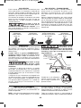
HAMMERHOOK
™
Your tool is equipped with a convenient hook
for hanging your tool. To use, simply open
hook until it snaps into the open position
(Fig. 9).
When using the HAMMERHOOK™ always
be aware that the accessory is exposed.
Always hang the tool in an area where
yourself and bystanders can not accidently
make contact with the accessory.
To reduce the risk of
injury, use care in
selecting the location for hanging the
tool.
• Select a suitably sized and shaped object
that will provide adequate hanging stability.
An unstable hanging surface could result in
the tool unexpectedly falling.
• Insure that the tool is hung out of the way of
walkways and working areas with
bystanders. The tool could be bumped or a
bystander could become entangled in the
power supply cord causing the tool to
unexpectedly fall.
To reduce the risk of
injury, Do not use the
hanging hook if it appears damaged or
deformed. This could result in unstable
hanging and the tool unexpectedly falling.
When not in use, always
close hook until it snaps
into the closed position.
-10-
HAMMERHOOK
™
FIG. 9
To Open
To Close
S
ELECTOR DIAL
The selector dial allows the tool to be set for
various drilling/hammer drilling applications.
Depress release button and turn selector dial
right or left depending on the below
applications.
When using demolition or chipping bits such as
bull points, chisels, spades, gouges, etc. the
“Hammer Only” mode must be selected.
Do not operate the
selection dial until the
tool come to a complete stop. Shifting during
rotation of the chuck can cause damage to the
tool.
S
ELECTOR DIAL - “VARIO-LOCK”
Adjusting the Vario-Lock: The vario-lock can
be set in any one of thirty-six (10˚
increments) positions. Choose a position
which is best suited for your operation.
Depress release button and turn the selector
dial, to the “vario-lock” setting. Next, rotate
the locking sleeve, along with the accessory,
to the desired position. Then turn the selector
dial to the “hammer only” setting and slightly
turn the locking sleeve to have it
automatically lock into a definite position.
Drilling only: Drilling/hammering: Vario-lock Hammering only:
used for drilling used for drilling allows for 36 desired used for light
wood, steel, etc. concrete positions of “hammer” chipping work
FIG. 8
2610047986_GBH2-28L 10/2/17 1:47 PM Page 10

T
OOL TIPS
Following a few simple tips will reduce wear
on the tool and the chance of injury to the
operator.
NOTE: The high efficiency available from
the rotary hammers can only be obtained if
sharp and undamaged accessories are used.
The “cost” to maintain sharp and undamaged
accessories is more than offset by the “time
saved” in operating the tool with sharp
accessories.
All hammers require a short period of time to
warm up. Depending on the room
temperature, this time may vary from
approximately 15 seconds (90˚F) to 2
minutes (32˚F).
A new hammer requires a break-in period
before full performance is realized. This
period may require up to 5 hours of
operation.
You will extend the life of your bits and do
neater work if you always put the bit in
contact with the workpiece BEFORE pulling
the trigger. During operation, hold the drill
firmly and exert moderate, steady pressure.
Too much pressure at low speed will stall the
hammer. Too little pressure will keep the bit
from cutting and cause excess friction by
sliding over the surface. This can be
damaging to the drill and bit.
Carbide tipped bits: Used for drilling stone,
concrete, cement, brick, cinder block and
other unusually hard non-metals.
3-JAW CHUCK
(Drill only mode)
The 3-Jaw Chuck with SDS-plus
®
Shank
Adaptor accessory can convert your tool for
use with straight shank bits.
Shanks of all drill bits should be wiped clean
prior to using and immediately after
removing.
Recall these instructions for safe
operation:
1.All work must be supported or secured
before drilling and steady, even pressure
applied in line with the drill bit.
2
.As the drill bit cuts through the opposite
side, reduce the pressure and continue
running the drill as the bit is withdrawn.
3.Some materials require slow drilling
speeds; whereas, others require higher
speed to produce the best results.
Materials such as glass, porcelain,
ceramics, tiles, plastics, etc., should be
drilled at low speeds with specially
designed drill bits and lubricants.
DRILLING WOOD OR PLASTIC
(Drill only mode)
If backing block is not used, ease up on the
pressure just before the bit breaks through
the wood to avoid splintering. Complete the
hole from the opposite side immediately after
the point breaks through. If bit binds, reverse
the drilling operation to help remove the bit
from the work.
DRILLING METAL
(Drill only mode)
There are two rules for drilling hard materials.
First, the harder the material, the greater the
pres sure you need to apply to the tool.
Second, the harder the material, the slower
the speed. Here are a couple of tips for
drilling in metal. Make a center punch in the
material for easier starting. Lubri cate the tip
of the bit occasionally with cutting oil except
when drilling soft metals such as alu minum,
cop per or cast iron. If the hole to be drilled is
fairly large, drill a smaller hole first, then
enlarge to the required size, it’s often faster
in the long run. Main tain enough pressure to
assure that the bit does not just spin in the
hole. This will dull the bit and greatly shorten
its life.
DRILLING MASONRY
Use carbide-tipped masonry bit for cinder
block, mortar, common brick, soft stone and
other materials. The amount of pressure to
be used is dependent upon the type of
material being drilled. Soft materials require
less pressure while the hard materials need
more pressure to prevent the drill bit from
spinning.
-11-
For selection of dust collection systems and
operating instructions, see the Operating /
Safety Instructions for ‘Dust Extraction
Attachments for Hammers and Hammer Drills’
included with your tool or with the dust
extraction attachment.
Dust Extraction
2610047986_GBH2-28L 10/2/17 1:47 PM Page 11

Accessories
If an extension cord is
necessary, a cord with
adequate size conductors that is capable
of carrying the current necessary for your
tool must be used. This will prevent
excessive voltage drop, loss of power or
overheating. Grounded tools must use 3-wire
extension cords that have 3-prong plugs and
receptacles.
NOTE: The smaller the gauge number, the
higher the cord capacity.
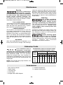
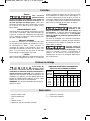
RECOMMENDED SIZES OF EXTENSION CORDS
120 VOLT ALTERNATING CURRENT TOOLS
* 360° Auxiliary Handle
* Depth Gauge
* Carrying Case
** 3-Jaw Chuck
** Straight Chuck SDS Adaptor
(*= standard equipment)
(**= optional accessories)
Extension Cords
-12-
Tool’s
Ampere
Rating
Cord Size in A.W.G. Wire Sizes in mm
2
Cord Length in Feet Cord Length in Meters
25 50 100 150
15 30 60 120
3-6
6-8
8-10
10-12
12-16
18
18
18
16
14
16
16
16
16
12
16
14
14
14
–
14
12
12
12
–
0.75
0.75
0.75
1.0
–
0.75
1.0
1.0
2.5
–
1.5
2.5
2.5
4.0
–
2.5
4.0
4.0
–
–
Service
Preventive maintenance
performed by unautho-
rized per so n nel may result in misplacing
of internal wires and components which
could cause serious hazard. We
recommend that all tool service be performed
by a Bosch Factory Service Center or Autho -
rized Bosch Service Station.
TOOL LUBRICATION
Your Bosch tool has been properly lubricated
and is ready to use. It is recommended that
tools with gears be regreased with a special
gear lubricant at every brush change.
CARBON BRUSHES
The brushes and commutator in your tool
have been engineered for many hours of
dependable service. To maintain peak
efficiency of the motor, we recommend every
two to six months the brush es be examined.
Only genuine Bosch replace ment brushes
specially designed for your tool should be
used.
BEARINGS
After about 300-400 hours of operation, or at
every second brush change, the bearings
should be replaced at Bosch Factory Service
C
enter or Au thorized Bosch Service Station.
Bearings which become noisy (due to heavy
load or very abrasive material cut ting) should
be replaced at once to avoid overheating or
motor failure.
Cleaning
To avoid accidents
always dis connect the
tool from the power supply before
cleaning or performing any main tenance.
The tool may be cleaned most effectively
with compressed dry air. Always wear
safety gog gles when cleaning tools with
compressed air.
Ventilation openings and switch levers must
be kept clean and free of foreign matter. Do
not at tempt to clean by inserting pointed
objects through openings.
Certain cleaning agents
and sol vents damage
plastic parts. Some of these are: gasoline,
carbon tetrachlo ride, chlo rinated cleaning
solvents, ammonia and house hold
detergents that contain ammonia.
Maintenance
2610047986_GBH2-28L 10/2/17 1:47 PM Page 12

-13-
Veuillez lire tous les avertissements et toutes les consignes de sécurité. Si
l'on n'observe pas ces avertissements et ces consignes de sécurité, il existe un
risque de choc électrique, d'incendie et/ou de blessures corporelles graves.
CONSERVEZ TOUS LES AVERTISSEMENTS ET TOUTES LES CONSIGNES
DE SÉCURITÉ POUR RÉFÉRENCE FUTURE.
Dans les avertissements, le terme « outil électroportatif » se rapporte à votre outil branché sur le secteur (avec fil) ou
à votre outil alimenté par piles (sans fil).
Avertissements généraux concernant la sécurité des outils électroportatifs
Sécurité du lieu de travail
Maintenez le lieu de travail propre et bien éclairé.
Les risques d’accident sont plus élevés quand on
travaille dans un endroit encombré ou sombre.
N’utilisez pas d’outils électroportatifs dans des
atmosphères explosives, comme par exemple en
présence de gaz, de poussières ou de liquides
inflammables. Les outils électroportatifs produisent
des étincelles qui risquent d’enflammer les poussières
ou les vapeurs.
Éloignez les enfants et les visiteurs quand vous vous
servez d’un outil électroportatif. Vous risquez une
perte de contrôle si on vous distrait.
Sécurité électrique
Les fiches des outils électroportatifs doivent
correspondre à la prise. Il ne faut absolument jamais
modifier la fiche. N’utilisez pas d’adaptateur de prise
avec des outils électroportatifs munis d’une fiche de
terre. Le risque de choc électrique est moindre si on
utilise une fiche non modifiée sur une prise qui lui
correspond.
Évitez tout contact du corps avec des surfaces reliées
à la terre tels que tuyaux, radiateurs, gazinières ou
réfrigérateurs. Le risque de choc électrique augmente
si votre corps est relié à la terre.
N’exposez pas les outils électroportatifs à la pluie ou
à l’humidité. Si de l’eau pénètre dans un outil
électroportatif, le risque de choc électrique augmente.
Ne maltraitez pas le cordon. Ne vous en servez
jamais pour transporter l’outil électroportatif, pour le
tirer ou pour le débrancher. Éloignez le cordon de la
chaleur, des huiles, des arêtes coupantes ou des
pièces mobiles. Les cordons abîmés ou emmêlés
augmentent les risques de choc électrique.
Si vous utilisez un outil électroportatif à l’extérieur,
employez une rallonge conçue pour l’extérieur. Ces
rallonges sont faites pour l’extérieur et réduisent le
risque de choc électrique.
S'il est absolument nécessaire d'utiliser l'outil
électroportatif dans un endroit humide, utilisez une
alimentation protégée par un disjoncteur de fuite de
terre (GFCI). L'utilisation d'un disjoncteur GFCI réduit
les risques de choc électrique.
Sécurité personnelle
Restez concentré, faites attention à ce que vous
faites, et servez-vous de votre bon sens lorsque vous
utilisez un outil électroportatif. N'employez pas
d’outils électroportatifs quand vous êtes fatigué ou
sous l’emprise de drogues, d’alcool ou de
médicaments. Quand on utilise des outils
Symboles relatifs à la sécurité
Les définitions ci-dessous décrivent le niveau de gravité pour chaque terme signalant un danger. Veuillez lire le
mode d’emploi et lire la signification de ces symboles.
!
C’est le symbole d’alerte relatif à la sécurité. Il est utilisé pour vous
avertir de l’existence possible d’un danger de lésion corporelle.
Obéissez à tous les messages relatifs à la sécurité qui suivent ce
symbole pour éviter tout risque de blessure ou même de mort.
DANGER indique une situation dangereuse qui, si elle n’est pas
évitée, causera la mort d’une personne ou une blessure grave.
AVERTISSEMENT indique une situation dangereuse qui, si elle
n’est pas évitée, pourrait causer la mort d’une personne ou une
blessure grave.
MISE EN GARDE, conjointement avec le symbole d’alerte en
liaison avec la sécurité, indique une situation dangereuse qui, si
elle n'est pas évitée, causera une blessure légère ou modérée.
2610047986_GBH2-28L 10/2/17 1:47 PM Page 13

-14-
électroportatifs, il suffit d’un moment d’inattention pour
causer des blessures corporelles graves.
Utilisez des équipements de sécurité personnelle.
Portez toujours une protection oculaire. Le port
d'équipements de sécurité tels que des masques
antipoussières, des chaussures de sécurité
antidérapantes, des casques de chantier et des
protecteurs d'oreilles dans des conditions appropriées
réduira le risque de blessure corporelle.
Évitez les démarrages intempestifs. Assurez-vous que
l'interrupteur est dans la position arrêt (Off) avant de
brancher l'outil dans une prise de courant et/ou un
bloc-piles, de le ramasser ou de le transporter. Le
transport d'un outil électroportatif avec le doigt sur la
gâchette ou le branchement de cet outil quand
l'interrupteur est en position de marche (ON) est une
invite aux accidents.
Enlevez toutes les clés de réglage avant de mettre
l’outil électroportatif en marche. Si on laisse une clé
sur une pièce tournante de l’outil électroportatif, il y a
risque de blessure corporelle.
Ne vous penchez pas. Conservez toujours une bonne
assise et un bon équilibre. Ceci vous permettra de
mieux maîtriser l’outil électroportatif dans des situations
inattendues.
Habillez-vous de manière appropriée. Ne portez pas
de vêtements amples ou de bijoux. Attachez les
cheveux longs. N’approchez pas les cheveux, les
vêtements ou les gants des pièces en mouvement.
Les vêtements amples, les bijoux ou les cheveux longs
risquent d’être happés par les pièces en mouvement.
Si l’outil est muni de dispositifs permettant le
raccordement d’un système d’aspiration et de
collecte des poussières, assurez-vous que ces
dispositifs sont raccordés et utilisés correctement.
L'utilisation d'un dépoussiéreur peut réduire les dangers
associés à l'accumulation de poussière.
Utilisation et entretien des outils
électroportatifs
Ne forcez pas sur l’outil électroportatif. Utilisez l’outil
électroportatif qui convient à la tâche à effectuer.
L’outil qui convient à la tâche fait un meilleur travail et
est plus sûr à la vitesse pour lequel il a été conçu.
Ne vous servez pas de l’outil électroportatif si son
interrupteur ne parvient pas à le mettre en marche ou
à l’arrêter. Tout outil électroportatif qui ne peut pas
être commandé par son interrupteur est dangereux et
doit être réparé.
Débranchez la fiche de la prise ou enlevez le bloc-pile
de l’outil électroportatif avant tout réglage,
changement d’accessoires ou avant de ranger l’outil
électroportatif. De telles mesures de sécurité
préventive réduisent le risque de démarrage intempestif
de l’outil électroportatif.
Rangez les outils électroportatifs dont vous ne vous
servez pas hors de portée des enfants et ne permettez
pas à des personnes qui ne connaissent pas l’outil
électroportatif ou qui ignorent ces consignes de s’en
servir. Les outils électroportatifs sont dangereux dans
les mains d’utilisateurs inexpérimentés.
Entretenez les outils électroportatifs. Vérifiez que les
pièces mobiles sont alignées correctement et ne
coincent pas. Vérifiez qu’il n’y a pas de pièces
cassées ou d’autre circonstance qui risquent
d’affecter le fonctionnement de l’outil électroportatif.
Si l’outil est abîmé, faites-le réparer avant de
l’utiliser. De nombreux accidents sont causés par des
outils électroportatifs mal entretenus.
Maintenez les outils coupants affûtés et propres. Les
outils coupants entretenus correctement et dotés de
bords tranchants affûtés sont moins susceptibles de
coincer et sont plus faciles à maîtriser.
Utilisez l'outil électroportatif, les accessoires et les
embouts d'outil, etc. conformément à ces
instructions, en tenant compte des conditions de
travail et des travaux à réaliser. L'emploi d’outils
électroportatifs pour des tâches différentes de celles
pour lesquelles ils ont été prévus peut résulter en une
situation dangereuse.
Entretien
Faites réparer votre outil électroportatif par un agent
de service qualifié n’utilisant que des pièces de
rechange identiques. Ceci assure que la sécurité de
l’outil électroportatif est préservée.
Règles de sécurité concernant les marteaux rotatifs
Portez des protecteurs d'oreilles quand vous utilisez
des perceuses à percussion. L'exposition au bruit
peut causer une perte d'acuité auditive.
Utilisez la ou les poignée(s) auxiliaire(s) si elle
est/elles sont fournie(s) avec l'outil. Une perte de
contrôle pourrait causer des blessures physiques.
Tenez l’outil électroportatif par ses surfaces de
préhension isolées lorsque vous effectuez une
opération à l’occasion de laquelle l’accessoire de
coupe risque d’entrer en contact avec un fil caché
ou avec son propre cordon d’alimentation. Tout
contact de l’accessoire de coupe avec un fil sous
tension risque de mettre aussi sous tension les
parties métalliques exposées de l’outil électroportatif,
ce qui pourrait causer un choc électrique pour
l’opérateur.
Utilisez des brides ou d’autres moyens pratiques de
brider ou de supporter la pièce sur une plate-forme
stable. Tenir la pièce à la main ou contre le corps est
instable et risque de résulter en une perte de contrôle.
Ne percez, fixez et ne rentrez pas dans des murs
existants ou autres endroits aveugles pouvant abriter
2610047986_GBH2-28L 10/2/17 1:47 PM Page 14

-15-
des fils électriques. Si cette situation est inévitable,
débranchez tous les fusibles ou les disjoncteurs
alimentant ce site.
Utilisez un détecteur de métaux afin d’établir s’il y a
des tuyaux d’eau ou à gaz dissimulés dans l’aire de
travail ou appelez la compagnie de service public
locale pour assistance avant de commencer
l’opération. Le fait de frapper une conduite de gaz ou
de couper dans celle-ci provoquera une explosion.
L’eau pénétrant dans un appareil électrique peut
entraîner une électrocution.
Utilisez toujours la poignée auxiliaire pour un
contrôle maximal sur le rebond ou la réaction de
couple. Ne tentez jamais d'utiliser cet outil d'une
seule main. L’embrayage à friction s’enclenche si vous
tenez fermement l’outil quand celui-ci subit un couple
de réaction ou un recul brutal.
Portez toujours des lunettes à coques latérales ou
des lunettes de protection en utilisant cet outil.
Utilisez un respirateur ou un masque antipoussières
pour les applications qui produisent de la poussière.
Les lunettes de sécurité ou la protection oculaire
permettent de dévier les fragments de matériau qui
pourraient être projetés vers votre visage et vos yeux.
La poussière générée ou les gaz libérés par le matériau
que vous travaillez (par ex. tuyaux à isolation amiante,
radon) peuvent causer des difficultés respiratoires.
Utilisez des gants rembourrés épais et limitez le
temps d'exposition en prenant des pauses
fréquentes. Les vibrations causées par l'action du
marteau-perceuse peuvent être nocives pour vos mains
et vos bras.
Placez le cordon à l'écart du foret en rotation.
N'enroulez pas le cordon autour de votre bras ou de
votre poignet. Si vous perdez contrôle et que le cordon
s'enroule autour de votre bras ou de votre poignet, il
peut vous emprisonner et vous blesser.
Placez-vous de manière à éviter d'être pris entre
l'outil ou la poignée latérale et les murs ou les
montants. Si le foret se coince ou grippe dans
l'ouvrage, le couple de réaction de l'outil pourrait
écraser votre main ou votre pied.
Ne frappez pas le foret avec une masse ou un
marteau à main en tentant de déloger un foret
grippé ou coincé. Des fragments métalliques
pourraient se détacher du foret et vous frapper ou
frapper des personnes présentes.
Ne posez jamais l'outil jusqu'à ce que le foret ou
l'accessoire se soit arrêté complètement.
N'utilisez pas de forets et d'accessoires émoussés
ou endommagés. Les forets émoussés ou
endommagés ont tendance à gripper dans l'ouvrage.
En retirant le foret de l'outil, évitez tout contact avec
la peau et utilisez des gants protecteurs appropriés
en saisissant le foret ou l'accessoire. Les accessoires
peuvent être chauds après une utilisation prolongée.
Ne laissez pas l'outil en marche tout en le portant à
votre côté. Le foret en rotation peut s'emmêler avec les
vêtements et causer des blessures.
Avertissements supplémentaires concernant la sécurité
L’emploi d’un GFCI et de dispositifs de protection
personnelle tels que gants et chaussures d’électricien en
caoutchouc améliorent votre sécurité personnelle.
N’utilisez pas un outil conçu uniquement pour le C.A.
sur une alimentation en C.C. Même si l’outil semble
fonctionner, les composants électriques d’un outil prévu
pour le C.A. tomberont probablement en panne et
risquent de créer un danger pour l’utilisateur.
Maintenez les poignées sèches et exemptes d’huile et
de graisse. On ne pas maîtriser un outil électroportatif
en toute sécurité quand on a les mains glissantes.
Créez un agenda d’entretien périodique pour votre
outil. Quand vous nettoyez un outil, faites attention
de n’en démonter aucune pièce car il est toujours
possible de mal remonter ou de pincer les fils
internes ou de remonter incorrectement les ressorts
de rappel des capots de protection. Certains agents de
nettoyage tels que l’essence, le tétrachlorure de
carbone, l’ammoniaque, etc. risquent d’abîmer les
plastiques.
Risque de blessure pour l'utilisateur. Le cordon
d'alimentation électrique ne doit être réparé que par un
Centre de service usine de Bosch ou par une Station
service agréée de Bosch.
Les travaux à la
machine tel que
ponçage, sciage, meulage, perçage et autres travaux
du bâtiment peuvent créer des poussières contenant
des produits chimiques qui sont des causes
reconnues de cancer, de malformation congénitale ou
d’autres problèmes reproductifs. Ces produits
chimiques sont, par exemple :
• Le plomb provenant des peintures à base de plomb,
• Les cristaux de silices provenant des briques et du
ciment et d’autres produits de maçonnerie, et
• L’arsenic et le chrome provenant des bois traités
chimiquement.
Le niveau de risque dû à cette exposition varie avec la
fréquence de ces types de travaux. Pour réduire
l’exposition à ces produits chimiques, il faut travailler
dans un lieu bien ventilé et porter un équipement de
sécurité approprié tel que certains masques à poussière
conçus spécialement pour filtrer les particules
microscopiques.
2610047986_GBH2-28L 10/2/17 1:47 PM Page 15

-16-
Symboles
I
M
P
O
R
T
A
N
T
:
C
e
r
t
a
i
n
s
d
e
s
s
y
m
b
o
l
e
s
s
u
i
v
a
n
t
s
p
e
u
v
e
n
t
ê
t
r
e
u
t
i
l
i
s
é
s
s
u
r
v
o
t
r
e
o
u
t
i
l
.
V
e
u
i
l
l
e
z
l
e
s
é
t
u
d
i
e
r
e
t
a
p
p
r
e
n
d
r
e
l
e
u
r
s
i
g
n
i
f
i
c
a
t
i
o
n
.
U
n
e
i
n
t
e
r
p
r
é
t
a
t
i
o
n
a
p
p
r
o
p
r
i
é
e
d
e
c
e
s
s
y
m
b
o
l
e
s
v
o
u
s
p
e
r
m
e
t
t
r
a
d
'
u
t
i
l
i
s
e
r
l
'
o
u
t
i
l
d
e
f
a
ç
o
n
p
l
u
s
e
f
f
i
c
a
c
e
e
t
p
l
u
s
s
û
r
e
.
Symbole Désignation / Explication
V Volts (voltage)
A Ampéres (courant)
Hz Hertz (fréquence, cycles par seconde)
W Watt (puissance)
kg Kilogrammes (poids)
min Minutes (temps)
s Seconds (temps)
Diamétre (taille des mèches de perceuse, meules, etc.)
n
0
Vitesse à vide (vitesse de rotation, à vide)
n Vitesse nominale (vitesse maximum pouvant être atteinte)
.../min
Tours ou mouvement alternatif par minute (tours, coups, vitesse en surface, orbites, etc.,
par minute)
0 Position d'arrêt (vitesse zéro, couple zéro ...)
1, 2, 3, ...
I, II, III,
Réglages du sélecteur (Réglages de vitesse, de couple ou de position. Un nombre plus
élevé signifie une vitesse plus grande)
0
Sélecteur variable à l'infini avec arrêt (La vitesse augmente depuis le réglage 0)
Flèche (action dans la direction de la flèche)
Courant alternatif (type ou caractéristique du courant)
Courant continu (type ou caractéristique du courant)
Courant alternatif ou continu (type ou caractéristique du courant)
Construction classe II (désigne des outils construits avec double isolation)
Borne de terre (borne de mise à la terre)
2610047986_GBH2-28L 10/2/17 1:47 PM Page 16

-17-
Symboles (suite)
IMPORTANT : Certains des symboles suivants peuvent être utilisés sur votre outil. Veuillez les étudier et apprendre
leur signification. Une interprétation appropriée de ces symboles vous permettra d'utiliser l'outil de façon plus
efficace et plus sûre.
Symbole Désignation / Explication
Désigne le programme de recyclage des piles Li-ion.
Désigne le programme de recyclage des piles Ni-Cad.
Alerte l’utilisateur pour lire le mode d’emploi
Alerte l’utilisateur pour porter des lunettes de sécurité
Ce symbole signifie que cet outil est approuvé par Underwriters Laboratories.
Ce symbole indique que ce composant est reconnu par Underwriters Laboratories.
Ce symbole signifie que cet outil est approuvé par Underwriters Laboratories
selon les normes des États-Unis et du Canada.
Ce symbole signifie que cet outil est approuvé par l'Association canadienne de
normalisation.
Ce symbole signifie que cet outil est approuvé par l'Association canadienne de
normalisation selon les normes des États-Unis et du Canada.
Ce symbole signifie que cet outil est approuvé par Intertek Testing Services selon
les normes des États-Unis et du Canada
Ce symbole signifie que cet outil se conforme aux normes mexicaines NOM.
2610047986_GBH2-28L 10/2/17 1:47 PM Page 17

-18-
Description fonctionnelle et spécifications
Débranchez la fiche de la prise de courant avant d'effectuer quelque
assemblage ou réglage que ce soit ou de changer les accessoires. Ces
mesures de sécurité préventive réduisent le risque d'une mise en marche accidentelle de l'outil.
Marteau rotatif
PARE-
POUSSIÈRE
PRISES D’AIR
LEVIER DE L’INTERRUPTEUR
D’INVERSION DE MARCHE
GÂCHETTE DE
COMMANDE À
VITESSE
VARIABLE
BUTÉE DE
PROFONDEUR
MANCHON DE
VERROUILLAGE
BOUTON DE BLOCAGE DE
LA BUTÉE DE PROFONDEUR
BOUTON DE
DECLENCHEMENT
CADRAN SELECTEUR
POIGNEE (PRISE)
POIGNEE AUXILIAIR
E
FIG. 1
HAMMERHOOK™
Numéro de modèle GBH2-28L
Type de tige SDS-plus
®
Capacités maximales :
Mèches à pointe au carbure (28 mm)
Mèches creuses à paroi mince (66 mm)
REMARQUE : Pour spécifications de l'outil, reportez-vous à la plaque signalétique de votre outil.
2610047986_GBH2-28L 10/2/17 1:47 PM Page 18

-19-
Débranchez la
fiche de la prise
de courant avant d'effectuer quelque assemblage ou
réglage que ce soit ou de changer les accessoires. Ces
mesures de sécurité préventive réduisent le risque d'une
mise en marche accidentelle de l'outil.Nettoyez la tige de
l’embout pour en enlever toute saleté, puis enduisez-la
modérément d’une huile ou graisse légère.
INSTALLATION D’ACCESSOIRES SDS-PLUS
®
Nettoyez la tige de l’embout de l’accessoire pour en
enlever toute saleté, puis enduisez-la modérément d’une
huile ou graisse légère.
Au pare-poussière, introduisez l’accessoire dans la
mandrin de retenue tout en le tordant et l’enfonçant
jusqu’à ce qu’il se verrouille auto ma tiquement en place.
Tirez sur l’embout pour vous assurer qu’il est bien
engagé dans la mandrin (Fig. 2).
DÉMONTAGE D’ACCESSOIRES SDS-PLUS
®
Les accessoires
peurent être
chauds après l’usage. Évitez tout contact avec la peau et
utilisez un chiffon ou des gants protecteurs appropriés
pour déposer.
Pour retirer un accessoire, tirez et tenez le manchon de
verrouillage vers l’arrière, et tirez le embout vers l’avant.
Essuyez tous les accessoires pour les nettoyer après les
avoir enlevés (Fig. 3).
Assemblage
POIGNEE AUXILIAIRE
La poignée auxiliaire, qui pivote sur 360°, doit être
utilisée pour supporter l’outil. Pour repositionner
et/ou faire pivoter la poignée, desserrez la manette,
déplacez la poignée à la position désiré le long du
cylindre, puis resserrez fermenment la manette (Fig. 4).
BUTÉE DE PROFONDEUR
La butée de profondeur permet de pré-régler la
profondeur de perçage ou d’effectuer des perçages
répétitifs à une profondeur donnée.
Réglage de la profondeur : Après avoir installé la
poignée auxiliaire, assurez-vous que l’accessoire est
inséré à fond du porte-outil avant de régler la butée de
profondeur (Fig. 5).
Pour régler la profondeur, appuyez sur le bouton de
blocage de la butée de profondeur et faites coulisser
cette dernière pour l’amener à la profondeur désirée.
Relâchez ensuite le bouton de blocage pour bloquer la
butée de profondeur en place.
1
2
3
PARE-
POUSSIÈRE
FIG. 2
2
1
MANCHON DE
VERROUILLAGE
FIG. 3
2
1
3
POIGNEE
(PRISE)
FIG. 4
X
BOUTON DE
BLOCAGE DE
LA BUTÉE DE
PROFONDEUR
BUTÉE DE
PROFONDEUR
FIG. 5
2610047986_GBH2-28L 10/2/17 1:47 PM Page 19

-20-
GÂCHETTE DE COMMANDE À VITESSE VARIABLE
Votre outil est équipé d’une gâchette à vitesse variable.
La vitesse de l’outil peut être contrôlée du régime
minimum au régime maximum spécifiés sur la plaque
signalétique par la pression que vous exercez sur la
gâchette. Exercez plus de pression pour augmenter la
vitesse et relâchez la pression pour diminuer la vitesse.
Cette commande précise de la vitesse vous permet de
percer sans poinçonnage central.
LEVIER DE L’INTERRUPTEUR
D’INVERSION DE MARCHE
Cet outil est pourvu du système inversion de marche
des brosses rotatives. Ce sys tème prolonge la vie utile
tout en optimalisant la puis san ce en marches avant et
arrière. Cet interrupteur d’inver sion peut être actionné
depuis le côté droit ou gauche de l’outil.
POUR LA ROTATION AVANT : faites glisser l’in terrup teur
jusqu’à la flèche marquée « forward » (Fig. 1).
POUR LA ROTA TION INVERSE : faites glisser
l’interrupteur jus qu’à la flèche marquée « reverse ».
REMARQUE : l’outil ne fonctionnera pas en position
intermédiaire.
EMBRAYAGE A GLISSEMENT
L’outil possède un embrayage interne préréglé.
L’embrayage est réglé de manière à ce qu’une force
suffisante soit transmise à la mèche pour la plupart des
conditions de perçage, mais il glissera lorsque la mèche
grippe dans le trou ou que l’outil est surchargé. Sachez
qu’en raison du réglage requis de l’embrayage, vous
pouvez être confronté à une réaction de couple un
instant avant que l’embrayage ne glisse. Cette réaction
de couple tordra le corps du marteau rotatif dans le
sens opposé à celui de la rotation de la mèche, à savoir,
en sens anti-horaire. À mesure que l’embrayage
glissera, la mèche cessera fort probablement de
tourner. Lorsque la force de grippage est retirée de la
mèche, l’embrayage se remet automatiquement à sa
position initiale. Si vous faites l’expérience d’un
grippage de la mèche et que l’embrayage commence à
glisser, mettez immédiatement l’outil à l’arrêt «OFF» et
corrigez la condition menant au grippage de la mèche.
CONTROLE DES RISQUES DE REBOND
La fonctionnalité de fermeture rapide permet un meilleur
contrôle et améliore le confort de l’utilisateur. L’outil
électrique s'éteint automatiquement en cas de rotation
soudaine et inattendue de l’outil autour de l’axe de
perçage (par exemple, si la mèche se coince dans de
l’acier renforcé ou se bloque dans un coin). Pour
remettre la machine en marche, relâchez l’interrupteur
de marche/arrêt, puis réactivez-le.
La fonction de contrôle des risques de rebond ne peut
s’activer que lorsque l’outil électrique fonctionne à la
vitesse maximum et quand il peut tourner librement
autour de l’axe du foret de perçage.
Consignes de fonctionnement
FIG. 6
FIG. 7
2610047986_GBH2-28L 10/2/17 1:47 PM Page 20
La page charge ...
La page charge ...
La page charge ...
La page charge ...
La page charge ...
La page charge ...
La page charge ...
La page charge ...
La page charge ...
La page charge ...
La page charge ...
La page charge ...
La page charge ...
La page charge ...
La page charge ...
La page charge ...
-
 1
1
-
 2
2
-
 3
3
-
 4
4
-
 5
5
-
 6
6
-
 7
7
-
 8
8
-
 9
9
-
 10
10
-
 11
11
-
 12
12
-
 13
13
-
 14
14
-
 15
15
-
 16
16
-
 17
17
-
 18
18
-
 19
19
-
 20
20
-
 21
21
-
 22
22
-
 23
23
-
 24
24
-
 25
25
-
 26
26
-
 27
27
-
 28
28
-
 29
29
-
 30
30
-
 31
31
-
 32
32
-
 33
33
-
 34
34
-
 35
35
-
 36
36


Bosch GBH2-28L-RT Mode d'emploi
- Catégorie
- Outils électroportatifs
- Taper
- Mode d'emploi
- Ce manuel convient également à
dans d''autres langues
- English: Bosch GBH2-28L-RT User guide
- español: Bosch GBH2-28L-RT Guía del usuario
Documents connexes
-
Bosch RH432VCQ Manuel utilisateur
-
Bosch Power Tools 11250VSRD Manuel utilisateur
-
-
-
-
-
-
-
-
Bosch Power Tools 11255VSR Manuel utilisateur