Blodgett ZEPHAIRE-E Mode d'emploi
- Catégorie
- Cuisinières
- Taper
- Mode d'emploi

BLODGETT OVEN COMPANY
www.blodgett.com
44 Lakeside Avenue, Burlington, Vermont 05401 USA Telephone (802) 658Ć6600 Fax: (802)864Ć0183
PN 90147 Rev P (5/11)
E 2011 - G.S. Blodgett Corporation
ZEPHAIREĆE
CONVECTION OVEN
INSTALLATION - OPERATION - MAINTENANCE
ZEPHAIREĆE
FOURS À CONVECTION
MANUEL D'INSTALLATION - FONCTIONNEMENT - ENTRETIEN

IMPORTANT
FOR YOUR SAFETY
Do not store or use gasoline or other flammable vapors or liquids in the vicinity
of this or any other appliance.
AVERTISSEMENT
Ne pas entreposer ni utiliser de l'essence ni d'autres vapeurs ou liquides inflamĆ
mables dans le voisinage de cet appariel, ni de tout autre appareil.
WARNING: IMPROPER INSTALLATION, ADJUSTMENT, ALTERATION, SERVICE OR
MAINTENANCE CAN CAUSE PROPERTY DAMAGE, INJURY OR DEATH. READ THE
INSTALLATION, OPERATING AND MAINTENANCE INSTRUCTIONS THOROUGHLY
BEFORE INSTALLING OR SERVICING THIS EQUIPMENT
AVERTISSEMENT: UNE INSTALLATION, UN AJUSTEMENT, UNE ALTÉRATION, UN
SERVICE OU UN ENTRETIEN NON CONFORME AUX NORMES PEUT CAUSER DES
DOMMAGES À LA PROPRIÉTE, DES BLESSURES OU LA MORT. LISEZ ATTENTIVEĆ
MENT LES DIRECTIVES D'INSTALLATION, D'OPÉRATION ET D'ENTRETIEN AVANT
DE FAIRE L'INSTALLATION OU L'ENTRETIEN DE CET ÉQUIPEMENT.
The information contained in this manual is important for the proper installation,
use, and maintenance of this oven. Adherence to these procedures and instrucĆ
tions will result in satisfactory baking results and long, trouble free service.
Please read this manual carefully and retain it for future reference.
Les informations données dans le présent manuel sont importantes pour installer,
utiliser et entretenir correctement ce four. Le respect de ces instructions et procéĆ
dures permettra d'obtenir de bons résultats de cuisson et une longue durée de serĆ
vice sans problèmes. Veuillez lire le présent manuel et le conserver pour pouvoir
vous y reporter à l'avenir.
Errors: Descriptive, typographic or pictorial errors are subject to correction. SpecificaĆ
tions are subject to change without notice.
Erreurs:Les erreurs de description, de typographie ou d'illustration font l'objet de
corrections. Les caractéristiques sont sujettes à modifications sans préavis.

THE REPUTATION YOU CAN COUNT ON
UNE RÉPUTATION SUR LAQUELLE VOUS POUVEZ COMPTER
For over a century and a half, The Blodgett Oven Company has been building
ovens and nothing but ovens. We've set the industry's quality standard for all
kinds of ovens for every foodservice operation regardless of size, application
or budget. In fact, no one offers more models, sizes, and oven applications
than Blodgett; gas and electric, fullĆsize, halfĆsize, countertop and deck, conĆ
vection, Cook'n Hold, CombiĆOvens and the industry's highest quality Pizza
Oven line. For more information on the full line of Blodgett ovens contact your
Blodgett representative.
Cela fait maintenant dessus un siècle et demi que Blodgett se spécialise dans
la fabrication de fours. Nous avons établi les normes de qualité qui s'appliĆ
quent dans l'industrie à tous les types de fours utilisés dans les services aliĆ
mentaires, quel qu'en soit la taille, l'exploitation ou le budget. En fait, ni n'offre
plus de modèles, de tailles et d'applications de fours que Blodgett. À gaz et
électriques. De tailles différentes, sur plan de travail et superposables. Qu'il
s'agisse de fours à convection, des modèles Cook'n Hold et CombiĆOven, ou
de la gamme de fours à pizzas de la plus haute qualité offerte sur le marché.
Pour de plus amples informations sur la gamme complète de fours Blodgett,
veuillez contacter votre représentant Blodgett.

Your Service Agency's Address:
Adresse de votre agence de service:
Model/Modèl:
Serial Number/Numéro de série:
Your oven was installed by/
Installateur de votre four:
Your oven's installation was checked by/
Contrôleur de l'installation de votre four:

Table of Contents/Table des Matières
Introduction
Oven Description and Specifications 2. . . .
Oven Components 3. . . . . . . . . . . . . . . . . . . .
Installation
Delivery and Location 4. . . . . . . . . . . . . . . . .
Utility Connections - Standards
and Codes 5. . . . . . . . . . . . . . . . . . . . . . . . . . .
Oven Assembly 6. . . . . . . . . . . . . . . . . . . . . .
NSF Bolts 6. . . . . . . . . . . . . . . . . . . . . . . . . .
Leg Attachment 7. . . . . . . . . . . . . . . . . . . . .
Caster Assembly 7. . . . . . . . . . . . . . . . . . . .
Double Section Assembly 8. . . . . . . . . . . .
Oven Leveling 8. . . . . . . . . . . . . . . . . . . . . .
Operation
Single Speed Blower 9. . . . . . . . . . . . . . . . . .
Single Speed Blower with Cavity Lights 10. .
Dual Speed Blower 11. . . . . . . . . . . . . . . . . . .
Standard Control for Zephaire E Plus 12. . .
Solid State Digital for Zephaire E Plus 13. . .
General Guidelines for Operating
Personnel 15. . . . . . . . . . . . . . . . . . . . . . . . . . . .
Suggested Times and Temperatures 16. . . .
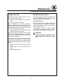
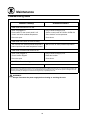
Maintenance
Cleaning and Preventative Maintenance 17.
Troubleshooting Guide 18. . . . . . . . . . . . . . . .
Introduction
Description et Spécifications du Four 20. . . .
Éléments du Four 21. . . . . . . . . . . . . . . . . . . . .
Installation
Livraison et Implantation 22. . . . . . . . . . . . . . .
Branchements de Service -
Normes et Codes 23. . . . . . . . . . . . . . . . . . . . .
Montage du Four 24. . . . . . . . . . . . . . . . . . . . .
Boulons NSF 24. . . . . . . . . . . . . . . . . . . . . . .
Assemblage des Pieds 25. . . . . . . . . . . . . . .
Montage des Roulettes 25. . . . . . . . . . . . . .
Montage de la Section Double 26. . . . . . . .
Mise à Niveau du Four 26. . . . . . . . . . . . . . .
Utilisation
Soufflerie Une Vitesse 27. . . . . . . . . . . . . . . . .
Soufflerie Une Vitesse avec Lumières
de Cavité 28. . . . . . . . . . . . . . . . . . . . . . . . . . . .
Soufflerie Deux Vitesses 29. . . . . . . . . . . . . . .
Commandes Standard pour
Zephaire E Plus 30. . . . . . . . . . . . . . . . . . . . . .
Commandes Numériques à SemiĆConducĆ
teurs pour Zephaire E Plus 31. . . . . . . . . . . . .
Consignes Générales à l'Intention
des Utilasateurs 34. . . . . . . . . . . . . . . . . . . . . .
Durées et Températures Suggérées 35. . . . .
Entretien
Nettoyage et Entretien Préventif 36. . . . . . . .
Guide de Détection des Pannes 37. . . . . . . .

Introduction
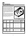
2
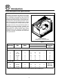
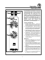
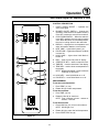
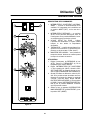
Oven Description and Specifications
Cooking in a convection oven differs from cooking
in a conventional deck or range oven since heated
air is constantly recirculated over the product by
a fan in an enclosed chamber. The moving air conĆ
tinually strips away the layer of cool air surroundĆ
ing the product, quickly allowing the heat to peneĆ
trate. The result is a high quality product, cooked
at a lower temperature in a shorter amount of time.
Blodgett convection ovens represent the latest adĆ
vancement in energy efficiency, reliability, and
ease of operation. Heat normally lost, is recircuĆ
lated within the cooking chamber before being
vented from the oven: resulting in substantial reĆ
ductions in energy consumption and enhanced
oven performance.
Air Flow Pattern for
Blodgett Electric Convection Ovens
Figure 1
KW/Section
Volts
Phase
Amperes
Electrical
Connection
KW
/S
ection Volts Phase
L1 L2 L3 N
C
onnection
AWG*
60 HZ UNITS
11 208 1 51 0 51 - 6
11 208 3 31 29 29 - 8
11 220Ć240 1 44 044- 6
11 220Ć240 3 26 24 24 - 8
11 440 3 15 14 14 - 12
11 480 3 14 13 13 - 12
50 HZ UNITS
11.0 220/380 3 18 16 16 2
Si
11.0 240/415 3 18 14 14 8
Size per
local code
11.0 230/400 3 18 15 15 3
local
code
* Electric connection wiring is sized for 90_C copper wire at 125% of rated input.

Introduction
3
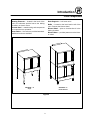
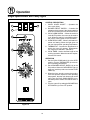
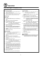
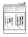
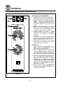
Oven Components
Heating Elements - located in the back of the
oven, the elements provide heat to the baking
chamber on electric ovens.
Control Panel - contains wiring and components
to control the oven operation.
Oven Racks - five racks are provided standard.
Additional racks are available.
Rack Supports - hold oven racks.
Baffle - located on the back interior wall of the
oven. Protects the blower wheel.
Blower Wheel - spins to circulate hot air in the
baking chamber.
Blower Motor - provides power to turn the blowĆ
er wheel.
ZEPHAIRE
T
-E
Single
ZEPHAIRE
T
-E
Double Stacked
Figure 2

Installation
4
Delivery and Location
DELIVERY AND INSPECTION
All Blodgett ovens are shipped in containers to
prevent damage. Upon delivery of your new oven:
D Inspect the shipping container for external damĆ
age. Any evidence of damage should be noted
on the delivery receipt which must be signed by
the driver.
D Uncrate the oven and check for internal damĆ
age. Carriers will accept claims for concealed
damage if notified within fifteen days of delivery
and the shipping container is retained for inĆ
spection.
The Blodgett Oven Company cannot assume
responsibility for loss or damage suffered in
transit. The carrier assumed full responsibility
for delivery in good order when the shipment
was accepted. We are, however, prepared to
assist you if filing a claim is necessary.
OVEN LOCATION
The well planned and proper placement of your
oven will result in long term operator convenience
and satisfactory performance.
The following clearances must be maintained beĆ
tween the oven and any combustible or nonĆcomĆ
bustible construction.
D Oven body right side - 1/2" (1.3 cm)
D Oven body left side - 1/2" (1.3 cm)
D Oven body back - 1/2" (1.3 cm)
D Oven body bottom - 1/2" (1.3 cm)
Adequate clearances must be available for servicĆ
ing.
D Keep the oven area free and clear of all combusĆ
tibles such as paper, cardboard, and flammable
liquids and solvents.
D Do not place the oven on a curb base or seal to
a wall. This will restrict the flow of air and prevent
proper ventilation resulting in damage to the
oven.
Before making any utility connections to this oven,
check the rating plate to be sure the oven specifiĆ
cations are compatible with the electrical services
supplied for the oven.
1. The rating plate is attached under ledge
above the door.

Installation
5
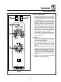
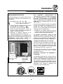
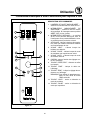
Utility Connections - Standards and Codes
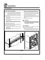
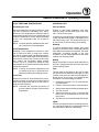
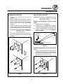
ELECTRICAL CONNECTION
The electric motor, indicator lights and related
switches are connected to the oven as follows:
The service line will enter trough the rear of the
oven and connected to the terminal block (see diaĆ
gram).
1. Remove the bottom trim and control panel.
Removal of the body side is not necessary.
2. Remove knockĆout in the rear of the unit and
run the supply power line to terminal block
and connect the wires.
3. Reinstall the control panel and the bottom
trim.
THE BLODGETT OVEN COMPANY CANNOT ASĆ
SUME RESPONSIBILITY FOR LOSS OR DAMAGE
SUFFERED AS A RESULT OF IMPROPER INSTALĆ
LATION.
Connect wires to
terminal block
Run supply line
through the knockĆout
Figure 3
THE INSTALLATION INSTRUCTIONS CONĆ
TAINED HEREIN ARE FOR THE USE OF QUALIĆ
FIED INSTALLATION AND SERVICE PERSONNEL
ONLY. INSTALLATION OR SERVICE BY OTHER
THAN QUALIFIED PERSONNEL MAY RESULT IN
DAMAGE TO THE OVEN AND/OR INJURY TO
THE OPERATOR.
Qualified installation personnel are individuals, a
firm, a corporation, or a company which either in
person or through a representative are engaged
in, and responsible for:
D the installation of electrical wiring from the elecĆ
tric meter, main control box or service outlet to
the electric appliance.
Qualified installation personnel must be experiĆ
enced in such work, familiar with all precautions
required, and have complied with all requirements
of state or local authorities having jurisdiction.
U.S. and Canadian installations
Installation must conform with local codes, or in
the absence of local codes, with the National ElecĆ
trical Code, ANSI/NFPA 70-Latest Edition and/or
Canadian National Electric Code C22.2 as applicaĆ
ble.
Appliance is to be installed with backflow prevenĆ
tion in accordance with applicable federal, provĆ
ince and local codes.
General export installations
Installation must conform with Local and National
installation standards. Local installation codes
and/or requirements may vary. If you have any
questions regarding the proper installation and/or
operation of your Blodgett oven, please contact
your local distributor. If you do not have a local disĆ
tributor, please call the Blodgett Oven Company at
0011Ć802Ć860Ć3700.

Installation
6
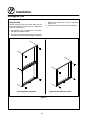
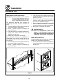
Oven Assembly
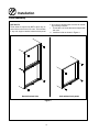
NSF BOLTS
These bolts are required by NSF to block any exĆ
posed hole on the back of an oven. This includes:
D any unit, single or stacked, without a back panel.
D any holes in stacked units not used for mountĆ
ing stacking brackets.
1. Locate the 5/16" bolts that were shipped with
the oven.
2. Install the bolts as shown in Figure 4.
Double Stacked Units Units without back panels
Figure 4

Installation
7
Oven Assembly
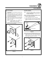
LEG ATTACHMENT
1. Push the oven onto a lift with the bottom of the
oven down.
2. Align the threaded stud in each leg with the
nut located inside each bottom corner of the
oven frame. Turn the legs clockwise and tightĆ
en to the nearest full turn.
3. Align the two leg plate holes in each leg with
those in the oven bottom. Secure each leg usĆ
ing two 1/2" bolts.
NOTE: If using casters see CASTER ASĆ
SEMBLY before proceeding.
4. Level the oven by screwing the adjustable leg
feet in or out as necessary.
6" (15 cm) Legs Shown
Figure 5
CASTER ASSEMBLY
NOTE: Install the locking casters on the front of
the oven. Install the nonĆlocking casters on
the back of the oven.
Casters for Single and Double Stacked Ovens:
1. Attach the legs as described.
2. Pry the adjustable feet out of the legs.
3. Insert one caster into each leg as shown.
Tighten the large hex nut to secure the castĆ
ers.
Adjustable
Leg Foot
Caster Assembly
Figure 6
Low Profile Casters for Double Stacked Ovens:
1. Align the three holes in each caster assembly
plate with those in the oven bottom. Secure
each caster using three 1/2" bolts.
Figure 7

Installation
8
Oven Assembly
DOUBLE SECTION ASSEMBLY
NOTE: Old style ovens refer to units with painted exĆ
posed rear angle. New style ovens refer to
units with rear angle iron enclosed in steel.
The following instructions apply to stacking two
new style ovens.
1. Secure the short legs to the bottom sections
as described.
2. Place the upper section in position on top of
the lower oven.
3. Attach the stacking brackets using the reĆ
maining 5/16" bolts shipped with the ovens.
4. Attach the flue connector.
The following instructions apply to stacking a new
style oven on an old style oven.
1. Secure the short legs to the bottom sections
as described.
2. Place the upper section in position on top of
the lower oven.
3. Attach the stacking brackets using the reĆ
maining 5/16" bolts shipped with the ovens.
4. Drill a clearance hole for a 5/16" bolt in the
angle iron of the old style oven. Use the holes
in the stacking brackets as a pilot.
5. Attach the stacking brackets to the old style
oven with the 5/16" bolts and nuts provided in
the kit.
6. Attach the flue connector.
WARNING!!
When stacking ovens be sure to remove
the single oven flue boxes prior to attachĆ
ing threeĆpiece connector.
OVEN LEVELING
After assembly, the oven should be leveled and
moved to the operating location.
1. The oven can be leveled by adjusting the feet
or casters located on the bottom of each leg.
Flue
Connector
Figure 8

Operation
9
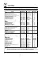
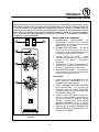
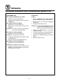
Single Speed Blower
BLOWER
ON
OFF
COOL
DOWN
MAN
AUTO
21
3
4
5
Figure 9
THE INFORMATION CONTAINED IN THIS SECĆ
TION IS PROVIDED FOR THE USE OF QUALIFIED
OPERATING PERSONNEL. QUALIFIED OPERATĆ
ING PERSONNEL ARE THOSE WHO HAVE
CAREFULLY READ THE INFORMATION CONĆ
TAINED IN THIS MANUAL, ARE FAMILIAR WITH
THE FUNCTIONS OF THE OVEN AND/OR HAVE
HAD PREVIOUS EXPERIENCE WITH THE OPĆ
ERATION OF THE EQUIPMENT DESCRIBED. ADĆ
HERENCE TO THE PROCEDURES RECOMĆ
MENDED HEREIN WILL ASSURE THE
ACHIEVEMENT OF OPTIMUM PERFORMANCE
AND LONG, TROUBLEĆFREE SERVICE.
CONTROL DESCRIPTION
1. BLOWER ON/OFF SWITCH - Controls the
operation of the blower. If the blower switch is
in the OFF position the oven will be turned off.
2. COOL DOWN SWITCH - When the switch is
in the AUTO position, the oven can be used to
cook. When the switch is in the MAN position,
the oven is cooling down for the next bake.
3. OVEN READY LIGHT Ć When lit indicates eleĆ
ments are heating. When the light goes out
the oven has reached operating temperature.
4. THERMOSTAT Ć Controls the temperature at
which the oven will operate. Temperatures
can range from 200Ć500_F (93Ć260_C).
5. COOK TIMER Ć Used to time the length of the
cooking operation. When the set time expires,
a buzzer will sound.
OPERATION
1. Set the COOL DOWN switch (2) to the AUTO
position. Turn the THERMOSTAT (4) to the deĆ
sired operating temperature.
2. Set the BLOWER ON/OFF SWITCH (1) to the
ON position. When the OVEN READY light (3)
goes out, load the product and set the COOK
TIMER (5).
3. When the timer sounds, remove the product.
If the next product requires a lower operating
temperature, then the cool down mode can be
used. Turn the COOL DOWN SWITCH (2) to
the MAN position. Make sure that the door is
open.
4. Turn the oven off by setting the BLOWER ON/
OFF SWITCH (1) to the OFF position.

Operation
10
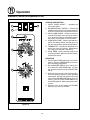
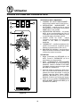
Single Speed Blower with Cavity Lights
LIGHTS
ON
OFF
COOL
DOWN
MAN
AUTO
BLOWER
ON
OFF
31
2
4
5
6
Figure 10
CONTROL DESCRIPTION
1. CAVITY LIGHTS ON/OFF - Operates the
oven cavity lights.
2. BLOWER ON/OFF SWITCH - Controls the
operation of the blower. If the blower switch is
in the OFF position the oven will be turned off.
3. COOL DOWN SWITCH - When the switch is
in the AUTO position, the oven can be used to
cook. When the switch is in the MAN position,
the oven is cooling down for the next bake.
4. OVEN READY LIGHT Ć When lit indicates eleĆ
ments are heating. When the light goes out
the oven has reached operating temperature.
5. THERMOSTAT Ć Controls the temperature at
which the oven will operate. Temperatures
can range from 200Ć500_F (93Ć260_C).
6. COOK TIMER Ć Used to time the length of the
cooking operation. When the set time expires,
a buzzer will sound.
OPERATION
1. Set the COOL DOWN switch (3) to the AUTO
position. Turn the THERMOSTAT (5) to the deĆ
sired operating temperature.
2. Set the BLOWER ON/OFF SWITCH (2) to the
ON position. When the OVEN READY light (4)
goes out, load the product and set the COOK
TIMER (6).
3. When the timer sounds, remove the product.
If the next product requires a lower operating
temperature, then the cool down mode can be
used. Turn the COOL DOWN SWITCH (3) to
the MAN position. Make sure that the door is
open.
4. Turn the oven off by setting the BLOWER ON/
OFF SWITCH (2) to the OFF position.

Operation
11
Dual Speed Blower
BLOWER
HI
OFF
COOL
DOWN
MAN
AUTO
LOW
21
3
4
5
Figure 11
CONTROL DESCRIPTION
1. BLOWER HI/LO/OFF SWITCH - Controls the
operation of the blower. If the blower switch is
in the OFF position the oven will be turned off.
2. COOL DOWN SWITCH - When the switch is
in the AUTO position, the oven can be used to
cook. When the switch is in the MAN position,
the oven is cooling down for the next bake.
3. OVEN READY LIGHT Ć When lit indicates eleĆ
ments are heating. When the light goes out
the oven has reached operating temperature.
4. THERMOSTAT Ć Controls the temperature at
which the oven will operate. Temperatures
can range from 200Ć500_F (93Ć260_C).
5. COOK TIMER Ć Used to time the length of the
cooking operation. When the set time expires,
a buzzer will sound.
OPERATION
1. Set the COOL DOWN switch (2) to the AUTO
position. Turn the THERMOSTAT (4) to the deĆ
sired operating temperature.
2. Set the BLOWER SWITCH (1) to the HI posiĆ
tion. When the OVEN READY light (3) goes
out, load the product and set the COOK TIMĆ
ER (5).
3. When the timer sounds, remove the product.
If the next product requires a lower operating
temperature, then the cool down mode can be
used. Set the BLOWER SWITCH (1) to the LO
position. Turn the COOL DOWN SWITCH (2)
to the MAN position. Make sure that the door
is open.
4. Turn the oven off by setting the BLOWER
SWITCH (1) to the OFF position.

Operation
12
Standard Control for Zephaire E Plus
LIGHTS
ON
OFF
COOL
DOWN
MAN
AUTO
BLOWER
31
2
4
5
6
HI
OFF
LOW
Figure 12
CONTROL DESCRIPTION
1. CAVITY LIGHTS ON/OFF - Operates the
oven cavity lights.
2. BLOWER HI/LO/OFF SWITCH - Controls the
operation of the blower. If the blower switch is
in the OFF position the oven will be turned off.
3. COOL DOWN SWITCH - When the switch is
in the AUTO position, the oven can be used to
cook. When the switch is in the MAN position,
the oven is cooling down for the next bake.
4. OVEN READY LIGHT Ć When lit indicates eleĆ
ments are heating. When the light goes out
the oven has reached operating temperature.
5. THERMOSTAT Ć Controls the temperature at
which the oven will operate. Temperatures
can range from 200Ć500_F (93Ć260_C).
6. COOK TIMER Ć Used to time the length of the
cooking operation. When the set time expires,
a buzzer will sound.
OPERATION
1. Set the COOL DOWN switch (3) to the AUTO
position. Turn the THERMOSTAT (5) to the deĆ
sired operating temperature.
2. Set the BLOWER SWITCH (2) to the HI posiĆ
tion. When the OVEN READY light (4) goes
out, load the product and set the COOK TIMĆ
ER (6).
3. When the timer sounds, remove the product.
If the next product requires a lower operating
temperature, then the cool down mode can be
used. Set the BLOWER SWITCH (2) to the LO
position. Turn the COOL DOWN SWITCH (3)
to the MAN position. Make sure that the door
is open.
4. Turn the oven off by setting the BLOWER
SWITCH (2) to the OFF position.

Operation
13
Solid State Digital for Zephaire E Plus
1
2
3
4
5
6
7
8
9
10
11
12
13
Figure 13
CONTROL DESCRIPTION
1. CAVITY LIGHTS ON/OFF - Operates the
oven cavity lights.
2. BLOWER ON/OFF SWITCH - Controls the
operation of the blower. If the blower switch is
in the OFF position the oven will be turned off.
3. COOL DOWN SWITCH - When the switch is
in the AUTO position, the oven can be used to
cook. When the switch is in the MAN position,
the oven is cooling down for the next bake.
4. DISPLAY - displays time or temperature and
other information related to oven function.
5. HEAT LAMP - lights when heater is on.
6. PULSE LAMP - lights when Pulsed Fan Mode
is turned on.
7. HOLD LAMP - lights when Hold Mode is
turned on.
8. DIAL - used to enter set points in display
9. START/STOP KEY - starts or stops the timer.
10. TIME KEY - used to show time in the display.
11. TEMP KEY - used to show set temperature in
the display.
NOTE: Actual temperature is shown while the
TEMP key is held down.
12. HOLD KEY - turns Hold Mode on or off.
13. PULSE KEY - turns Pulse Mode on or off.
PROGRAMMING
To set the cook temperature:
1. Press TEMP (11) key.
2. Rotate dial (8) to enter temperature.
To set the cook time:
1. Press TIME (10) key.
2. Rotate the dial (8) to enter time.
NOTE: Time is entered in hours : minutes or
minutes : seconds.
To set the hold time:
1. Press HOLD key (12) to turn hold mode on.
NOTE: HOLD light is on.
2. Rotate dial (8) to enter the hold temperature.
3. Press START/STOP key (9)

Operation
14
Solid State Digital for Zephaire E Plus
To set the pulse time:
1. Press PULSE KEY (13) to turn pulse mode on.
NOTE: Pulse light is on.
2. Rotate DIAL (8) to enter the pulse time. Pulse
time is a portion of the preĆset cook time.
OPERATION
Cook Only:
1. Turn the BLOWER switch (2) to the desired poĆ
sition.
2. Enter the cook time and temperature.
3. Load product into the oven.
NOTE: The display reads LOAD when the
oven is near the set temperature.
4. Press the START/STOP key (9). The timer beĆ
gins to count down.
5. When the cook timer reaches 00:00 the buzzĆ
er sounds and the display reads DONE.
6. Press the START/STOP key (9) to silence the
buzzer.
7. Remove the product.
Cook with Hold:
NOTE: HOLD light is on when hold mode is on
and off when hold mode is off.
1. Turn the BLOWER switch (2) to the desired
position.
2. Enter the cook time and temperature.
3. Press the HOLD key (12). Enter the hold temĆ
perature.
4. Load product into the oven.
NOTE: The display reads LOAD when the
oven is near the set temperature.
5. Push the START/STOP (9) key. Timer begins
to count down.
6. When the cook timer reaches 00:00 the buzzĆ
er sounds and the display reads DONE. The
buzzer turns off after a few seconds. The disĆ
play reads HOLD until the oven reaches the
hold temperature. Then the timer begins to
count up.
7. Push the START/STOP key (9) to stop timer.
8. Remove the product.
9. Push HOLD (12) key to turn off hold mode.
Cook with Pulse:
NOTE: PULSE light is on when pulse mode is on
and off when pulse mode is off.
1. Turn the BLOWER switch (2) to the desired
position.
2. Enter cook time and cook temperature.
3. Press PULSE KEY (13). Enter the pulse time.
NOTE: Pulse time is a portion of the cook time
and does not increase the previously
entered cook time.
4. Load product into the oven.
NOTE: The display reads LOAD when the
oven is near the set temperature.
5. Push START/STOP KEY (9). The timer begins
to count down the cook time. The oven will be
in pulse mode for the set pulse time. Once the
set time has expired, the unit will automatically
switch to cook mode and continue counting
down.
6. When the cook timer reaches 00:00 the buzzĆ
er sounds and the display reads DONE.
7. Push the START/STOP KEY (9) to turn the
buzzer off.
8. Remove the product.
WARNING!!
A complete five minute shutdown must be
observed before the oven is relighted.

Operation
15
General Guidelines for Operating Personnel
COOK TIMES AND TEMPERATURES
Preheating the oven
Always preheat the oven before baking or roastĆ
ing. We recommend preheating 50_F (28_C)
above the cook temperature to offset the drop in
temperature when the doors are opened and cold
product is loaded into the oven. Set the thermostat
to the cook temperature after the product is
loaded.
NOTE: For frozen product, preheat the oven 100_F
(56_C) above the cook temperature.
Cook Temperatures
Generally, cook temperatures should be 50_F
(28_C) lower than deck or range oven recipes.
Use this as a starting point and adjust the temperĆ
ature as necessary. If the edges of the product are
done but the center is raw, or if there is color variaĆ
tion, reduce the thermostat setting another
15Ć25_F (10Ć15_C). Continue to reduce the cook
temperature on successive loads until the desired
results are achieved.
NOTE: Cooking at excessive temperatures will
not reduce cook time, it will produce unĆ
satisfactory baking and roasting results.
Cook Time
Check the product in about half the time recomĆ
mended for deck or range oven recipes. Record
times and temperatures which provide best reĆ
sults for future reference.
NOTE: Cook time will vary with the amount of
product loaded, the type of pan and the
temperature.
OPERATING TIPS
Pans and Racks
Product or pan height determines how many
racks are used. The oven holds up to 10 18" x 26"
(45.7 x 66.0 cm) bun pans.
Load the oven from the bottom, centering the pans
on the rack. Never place a pan or aluminum foil on
the bottom of the oven. This obstructs the flow of
air and results in uneven baking and roasting.
Roasting
To reduce shrinkage when roasting, place meat
directly on the racks. Place a sheet pan oneĆhalf
full of water in the bottom rack position. The water
evaporates, increasing humidity in the oven
chamber. The pan catches grease from the meat,
making oven cleaning easier.
Baking
Weigh the product to ensure equal distribution in
each pan. Varying amounts of product will cause
uneven baking results.
Fans
The fan must be operating for the oven to heat.
Use the Pulse Plus feature to allow light or liquid
product to set in the pan and to avoid rippling toĆ
wards the fan. If your oven is not equipped with
this feature use the following procedure.
1. Preheat the oven 25_F (15_C) above the bakĆ
ing temperature.
2. Load the oven with product. Close the doors.
3. Set the thermostat to the baking temperature.
4. Turn the oven off.
5. Allow the product to set for 5Ć7 minutes with
the fan off. The residual heat in the oven sets
the product.
6. Turn the oven on for the remainder of the bake.
Lights
Turn the oven lights off when not viewing the prodĆ
uct. Leaving the lights on for extended periods of
time shortens the bulb life considerably.

Operation
16
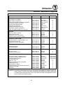
Suggested Times and Temperatures
Product Temperature Time # Shelves
Meats
Hamburger Patties (5 per lb)
Steamship Round (80 lb. quartered)
Standing Rib Choice (20 lbs, trimmed, rare)
Banquet Shell Steaks (10 oz. meat)
Swiss Steak after Braising
Baked Stuffed Pork Chop
Boned Veal Roast (15 lbs.)
Lamb Chops (small loin)
Bacon (on racks in 18" x 26" pans)
400_F (205_C)
275_F (135_C)
235_F (115_C)
450_F (235_C)
275_F (135_C)
375_F (190_C)
300_F (150_C)
400_F (205_C)
400_F (205_C)
8Ć10 mins.
2 hrs 45 mins.
2 hrs 45 mins.
7Ć8 mins.
1 hr.
25Ć30 mins.
3 hrs. 10 mins.
7Ć8 mins.
5Ć7 mins.
10
2
2
5
5
5
2
5
10
Poultry
Chicken Breast & Thigh
Chicken Back & Wing
Chicken (2
1
/
2
lbs. quartered)
Turkey Rolled (18 lb. rolls)
350_F (175_C)
350_F (175_C)
350_F (175_C)
310_F (155_C)
40 mins.
35 mins.
30 mins.
3 hrs 45 mins.
5
5
5
3
Fish and Seafood
Halibut Steaks, Cod Fish (frozen 5 oz)
Baked Stuffed Lobster (2
1
/
2
lb.)
Lobster Tails (frozen)
350_F (175_C)
400_F (205_C)
425_F (220_C)
20 mins.
10 mins.
9 mins.
5
3
5
Cheese
Macaroni & Cheese Casserole
Melted Cheese Sandwiches
350_F (175_C)
400_F (205_C)
30 mins.
8 mins.
5
10
Potatoes
Idaho Potatoes (120 ct.)
Oven Roasted Potatoes (sliced or diced)
400_F (205_C)
325_F (165_C)
50 mins.
10 mins.
5
5
Baked Goods
Frozen Berry Pies (22 oz)
Fresh Apple Pie (20 oz.)
Pumpkin Pies (32 oz.)
Fruit Crisp
Bread (24 Ć 1 lb. loaves)
Southern Corn Bread
Baking Soda Biscuits
Brown & Serve Rolls
Sheet Cakes (5 lb. mixed batter per pan)
Chocolate Cake
Brownies
325_F (150_C)
350_F (175_C)
300_F (150_C)
300_F (150_C)
325_F (155_C)
375_F (190_C)
400_F (205_C)
350_F (175_C)
325_F (160_C)
325_F (160_C)
325_F (150_C)
35 mins.
25Ć30 mins.
30Ć50 mins.
25 mins.
30 mins.
15Ć20 mins.
6 mins.
15 mins.
16Ć18 mins.
20 mins.
15 mins.
5 (30 pies)
5 (30 pies)
5 (20 pies)
5
3
5
5
5
5
5
5
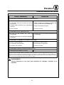
NOTE: Actual times and temperatures may vary considerably from those shown above. They are affected
by weight of load, temperature of the product, recipe, type of pan and calibration of thermostat.
Should your recipe vary, write in your proven time and temperature for ready reference.
La page charge ...
La page charge ...
La page charge ...
La page charge ...
La page charge ...
La page charge ...
La page charge ...
La page charge ...
La page charge ...
La page charge ...
La page charge ...
La page charge ...
La page charge ...
La page charge ...
La page charge ...
La page charge ...
La page charge ...
La page charge ...
La page charge ...
La page charge ...
La page charge ...
La page charge ...
-
 1
1
-
 2
2
-
 3
3
-
 4
4
-
 5
5
-
 6
6
-
 7
7
-
 8
8
-
 9
9
-
 10
10
-
 11
11
-
 12
12
-
 13
13
-
 14
14
-
 15
15
-
 16
16
-
 17
17
-
 18
18
-
 19
19
-
 20
20
-
 21
21
-
 22
22
-
 23
23
-
 24
24
-
 25
25
-
 26
26
-
 27
27
-
 28
28
-
 29
29
-
 30
30
-
 31
31
-
 32
32
-
 33
33
-
 34
34
-
 35
35
-
 36
36
-
 37
37
-
 38
38
-
 39
39
-
 40
40
-
 41
41
-
 42
42


Blodgett ZEPHAIRE-E Mode d'emploi
- Catégorie
- Cuisinières
- Taper
- Mode d'emploi
dans d''autres langues
Documents connexes
-
Blodgett SHO-E Mode d'emploi
-
-
Blodgett ZEPHAIRE-G Mode d'emploi
-
Blodgett Zephaire-200-E Le manuel du propriétaire
-
-
-
-
-
-
Blodgett CTB BASE 2401 Mode d'emploi