Broan FG6RA Manuel utilisateur
- Catégorie
- Cheminées
- Taper
- Manuel utilisateur

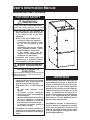
User’s Information Manual
Residential Gas Furnaces
FOR YOUR SAFETY
— Do not store or use gasoline or
other fl ammable vapors and liquids
in the vicinity of this or any other
appliance.
— WHAT TO DO IF YOU SMELL GAS:
• Do not try to light any appliance.
• Do not touch any electrical switch;
do not use any phone in your
building.
• Immediately call your gas supplier
from a neighbor’s phone. Follow
the gas supplier’s instructions.
• If you cannot reach your gas
supplier, call the fi re department.
• Extinguish any open fl ame.
— Installation and service must be
performed by a qualifi ed installer,
service agency, or the gas supplier.
— Ne pas entreposer ni utiliser de
l’essence ni d’autres vapeurs ou liquides
infl ammables dans le voisinage de cet
appareil, ni de tout autre appareil.
— QUE FAIRE S’UL Y A UNE ODEUR DE
GAZ
• Ne pas tenter d’allumer aucun
appareil.
• Ne toucher à aucun interrupteur
électrique; n’utiliser aucun téléphone
dans le bâtiment.
• Appeler immédiatement le fournisseur
de gaz en employant le téléphone
d’un voisin. Respecter à la lettre les
instructions du fournisseur de gaz.
• Si personne ne répond, appeler le
service des incendies.
— L’installation et l’entretien doivent être
effectués par un installateur qualifi é, un
organisme de service ou le fournisseur
de gaz.
IMPORTANT
Read this owner information thoroughly be-
fore attempting to operate or maintain this
furnace to become familiar with the capa-
bilities and use of your heating appliance.
Keep this with literature on other applianc-
es where you have easy access to it in the
future. If a problem occurs, check the in-
structions and follow the recommendations
given. If the suggestions do not eliminate
your problem, call your NORDYNE Servic-
ing Contractor (Service PRO).
Any additions, changes, or conversions re-
quired in order for the appliance to satisfac-
torily meet the application needs must be
made by a qualifi ed installer, service agen-
cy, or the gas supplier using factory speci-
fi ed and approved parts.
WARNING:
FIRE OR EXPLOSION HAZARD
Failure to follow safety precautions exactly could
result in serious injury, death or property damage.
AVERTISSEMENT
RISQUE D’INCENDIE OU
D’EXPLOSION
Le non-respect des consignes de sécurité pourrait
entraîner des blessures graves, la mort ou des
dommages matériels.

2
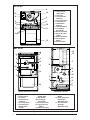
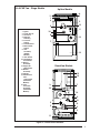
1 Ignitor
2 Flame Sensor
(Not Shown)
3 Gas Valve
4 Flame Roll-out
Switch(s)
5 Pressure Switch
6 Control Board
7 Blower Door
Switch(s)
8 Exhaust Adapter
9 Low Voltage
Transformer
10 Burner Assembly
11 Supply Air Limit
Switch
12 Blower Assembly
13 Induced Draft
Blower
14 Vent Transition
80+ AFUE
2
5
7
6
3
10
4
1
11
8
12
14
13
9
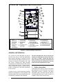
8 Vent Assembly
(Upfl ow Only)
9 Vent Switch
10 Low Voltage
Transformer
11 Burner Assembly
12 Supply Air Limit
Switch
13 Blower Assembly
14 Induced Draft
Blower
15 Combustion Tube
w/insulation
(Downfl ow Only)
16 Vent Transition
Assembly
(Downfl ow Only)
Upfl ow/Horizontal Furnace
Upfl ow/Horizontal Furnace
5
2
9
3
4
1
6
7
13
15
10
12
14
16
11
Downfl ow Furnace
Figure 1. Furnace Parts Identifi ed
13
6
5
9
7
4
12
11
10
1
3
14
8
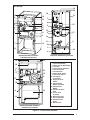
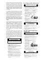
80+ AFUE
1 Ignitor
2 Flame Sensor
3 Gas Valve
4 Flame Roll-out
Switch(s)
5 Pressure Switch
6 Control Board
7 Blower Door
Switch

3
90+ AFUE
1 Igniter (Not Shown)
2 Flame Sensor (Not Shown)
3 Gas Valve
4 Flame Roll-out Switch(s)
5 Pressure Switch
7 Control Board
8 Blower Door Switch
9 Vent Safety Switch
10 Low Voltage
Transformer
11 Supply AIr Limit
Switch
12 Circulating Air
Blower Assembly
13 Induced Draft
Blower
14 Condensate Drain
Tube
15 In-Line Drain
Assembly
16 Burner View Port
17 Front Header Box
18 Combustion Air
Intake
19 Exhaust Vent
Upfl ow/Horizontal Full Size
Condensing Furnaces
Downfl ow Condensing Furnace
10
7
8
13
5
9
14
11
3
1
4
16
2
17
15
12
18
19
Figure 2. Furnace Parts Identifi ed
4
1
7
8
9
13
5
19
18
17
2
10
15
11
16
3
6
12
14
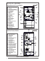
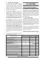
Upfl ow/Horizontal Compact
Condensing Furnaces
14
4
8
9
5
19
18
17
10
15
13
16
3
7
12

4
Figure 3. Furnace Parts Identifi ed
1 Igniter (Not Shown)
2 Flame Sensor
(Not Shown)
3 Gas Valve
4 Flame Roll-out Switch(s)
5 Pressure Switch
6 U.S. PC Board
7 Control Board
8 Blower Door Switch
(Not Shown)
9 Vent Safety Switch
10 Low Voltage Transformer
11 Supply Air Limit Switch
12 Circulating Air Blower
Assembly- (Not Shown)
13 Induced Draft Blower
14 Condensate Drain Tube
(Not Shown)
15 In-Line Drain Assembly
16 Burner View Port
17 Front Header Box
18 Combustion Air Intake
19 Exhaust Vent
20 Choke
1 Igniter (Not Shown)
2 Flame Sensor (Not Shown)
3 Gas Valve
4 Flame Roll-out Switch(s)
5 Condensate Pressure Switch
6 Pressure Switch
7 Control Board
8 Blower Door
Switch
9 Vent Safety Switch
10 Low Voltage
Transformer
11 Supply Air Limit
Switch
12 Circulating Air
Blower Assembly-
13 Induced Draft
Blower
14 Condensate Drain Tube
(Not Shown)
15 In-Line Drain
Assembly
16 Burner View Port
17 Front Header Box
18 Combustion Air
Intake (Not Shown)
19 Exhaust Vent
3
4
11
17
19
6
7
8
13
16
9
5
15
10
12
Downfl ow Furnace Models
3
4
9
10
11
7
13
17
19
15
16
18
5
2
1
6
20
90+ AFUE Two - Stage Models
Upfl ow/Horizontal Furnace Models

5
Figure 4. Furnace Parts Identifi ed
80+ AFUE Two - Stage Models
2
5
7
6
3
10
4
1
11
9
8
12
14
13
Upfl ow Models
3
4
1
6
7
13
15
10
12
9
5
2
11
16
14
Downfl ow Models
1 Igniter
2 Flame Sensor
3 Gas Valve
4 Roll-Out
Switch(s)
5 Pressure
Switch
6 Control Board
7 Blower Door
Switch
8 Vent
Assembly
(Upfl ow
Models)
9 Vent Switch
10 Low Voltage
Transformer
11 Burner
Assembly
12 Supply Air
Limit Switch
13 Blower
Assembly
14 Inducer
15 Combustion
Tube
w/insulation
(Downfl ow
Models)
16 Vent
Transition
Assembly
(Downfl ow
Models)

6
GENERAL INFORMATION
This furnace has been designed and built to
provide many years of safe and dependable
home comfort, providing it is properly installed
and maintained. With regular maintenance, this
furnace will operate satisfactorily year after
year. Abuse, improper use, and/or improper
maintenance can shorten the life of the furnace
and create hazards for you. Please read this
manual carefully to familiarize yourself with op-
eration, maintenance, and safety procedures
for this furnace.
A regular service and maintenance schedule
should be established to insure effi cient and
safe operation of the furnace. See Section 5 for
maintenance procedures and schedules.
1. Safety Information
The furnace area and the vicinity of any other
gas appliance must be kept clear and free of
combustible materials, gasoline, and other
fl ammable vapors and liquids. Do not store or
use fl ammable items such as paint, varnish, or
strippers in the vicinity of the furnace.
Devices attached to the fl ue or vent for the
purpose of reducing heat loss up the chim-
ney have not been tested and have not
been included in the design certifi cation of
this furnace. We, the manufacturer, can not
and will not be responsible for injury
Figure 5. Location of Major Components
12 Supply Air Limit Switch
13 Circulating Air
Blower Assembly-
14 Induced Draft Blower
15 Condensate Drain Tube
(Not Shown)
16 In-Line Drain Assembly
17 Burner View Port
1 Igniter
(Not Shown)
2 Flame Sensor
(Not Shown)
3 Gas Valve
4 Flame Roll-out
Switch(s)
5 Condensate
Pressure Switch
6 Pressure Switch
7 Control Board
8 Add On Board
9 Blower Door
Switch
10 Vent Safety Switch
11 Low Voltage
Transformer
18 Front Header Box
19 Combustion Air
Intake (Not Shown)
20 Exhaust Vent
21 Variable Speed Blower Kit
22 Gas Manifold Assembly
23 Burner Box Assembly
3
4
12
18
14
7
9
11
23
5
6
22
10
16
13
15
21
8
17
20
2
1
95+ AFUE Two - Stage Models and iQ Drive Furnace

7
Do not use the furnace closet or area next to the
furnace as a storage area. This area must be
kept clear, clean, and free of lint. The furnace
must also be kept clear of loose or exposed
insulation materials. Examine the furnace area
when the furnace is installed or when insulation
is added. Some insulation materials may be
combustible.
For proper and safe operation, the furnace
needs air for combustion and ventilation. Do not
block or obstruct air openings on the furnace,
or any air openings where the furnace may be
installed, including any surrounding spaces.
Should the gas supply fail to shut off or if
overheating occurs, shut off gas valve to
the furnace before shutting off electrical
supply.
Do not use this furnace if any part has been
under water. A fl ood-damaged furnace is
extremely dangerous. Attempts to use the
furnace can result in fi re or explosion. A
qualifi ed service agency should be contacted
to inspect the furnace and to replace all gas
controls, control system parts, electrical parts
that have been wet or the furnace if deemed
necessary.
Familiarize yourself with the controls that
shut off the gas and electrical power to the
furnace. If the furnace is to be shut down for an
extended period of time, turn off both the gas
and electrical power. For your safety always
turn off both the gas and electrical power
before performing service or maintenance on
the furnace.
For 2-Stage and 95+ Models Only
For 80+ and 90+ Single Stage
Models Only
1. STOP! Read the safety information above on this label.
2. Set the thermostat to the lowest setting.
3. Turn off all electrical power to the appliance.
4. The appliance’s ignition device automatically lights the
burner. Do not try to light burner by hand.
5. Remove the control access door/panel (upper door if
two-door model).
6. Move the gas control switch to the “OFF” position.
(See Figure 1)
7. Wait five (5) minutes to clear out any gas. Then
smell for gas, including near the floor. If you
smell gas, STOP! Follow “B”
in above information. If
you don’t smell gas, go
to the next step.
8. Move the gas control
switch to the “ON”
position. (See Figure 1)
9. Replace the control
access door/panel
(upper door if two-door
model).
10. Turn on all electrical power to the appliance.
11. Turn the thermostat to a desired setting.
12. If the appliance will not operate, follow the instructions
“To Turn Off Gas To Appliance” and call your service
technician or gas supplier.
1. Set the thermostat to the lowest setting.
2. Turn off all electrical power to the appliance if service is
to be performed.
3. Remove the control access door/panel (upper door if
two-door model).
4. Move the gas control switch to the “OFF” position. Do
not use force. (See Figure 1)
5. Replace the control access door/panel (upper door if
two-door model).
TO TURN OFF
GAS TO APPLIANCE
OPERATING INSTRUCTIONS
SWITCH
(INTERRUPTEUR)
Figure 1
A. This appliance does not have a pilot. It is equipped with
an ignition device which automatically lights the burner.
Do
not try to light the burner by hand.
B. BEFORE OPERATING smell all around the appliance
area for gas. Be sure to smell next to the floor because
some gas is heavier than air and will settle on the floor.
WHAT TO DO IF YOU SMELL GAS
• Do not try to light any appliance.
• Do not touch any electrical switch; do not use any phone
in your building.
• Immediately call your gas supplier from a neighbor’s
phone. Follow the gas supplier’s instructions.
• If you cannot reach your gas supplier, call the fire
department.
C.Use only your hand to push in or turn the gas control
knob. Never use tools. If the knob will not push in or
move by hand, do not try to repair it, call a qualified
service technician. Force or attempted repair may result
in a fire or explosion.
D.Do not use this appliance if any part has been under
water. Immediately call a qualified service technician to
inspect the appliance and to replace any part of the
control system and any gas control which has been
under water.
FOR YOUR SAFETY READ
BEFORE OPERATING
WARNING:
If you do not follow these instructions
exactly, a fire or explosion may result causing
property damage, personal injury, or loss of life.
1. STOP! Read the safety information above on this label.
2. Set the thermostat to the lowest setting.
3. Turn off all electrical power to the appliance.
4. The appliance’s ignition device automatically lights the
burner. Do not try to light burner by hand.
5. Remove the control access door/panel (upper door if
two-door model).
6. Move the gas control knob clockwise
to “OFF”.
(See Figure 1)
7. Wait five (5) minutes to clear out any gas. Then smell
for gas, including near the floor. If you smell gas,
STOP! Follow “B” in above information. If you don’t
smell gas, go to the next step.
8. Move the gas control knob
counterclockwise
to “ON”.
(See Figure 1)
9. Replace the control
access door/panel
(upper door if two-door
model).
10. Turn on all electrical
power to the appliance.
11. Turn the thermostat to a
desired setting.
12. If the appliance will not operate, follow the instructions
“To Turn Off Gas To Appliance” and call your service
technician or gas supplier.
1. Set the thermostat to the lowest setting.
2. Turn off all electrical power to the appliance if service is
to be performed.
3. Remove the control access door/panel (upper door if
two-door model).
4. Move the gas control knob clockwise
to “OFF”. Do
not use force. (See Figure 1)
5. Replace the control access door/panel (upper door if
two-door model).
TO TURN OFF
KNOB
(ROBINET)
Figure 1
OPERATING INSTRUCTIONS
GAS TO APPLIANCE

8
CAUTION:
Combustion air must not be drawn
from a corrosive atmosphere.
To maximize heat exchanger life, the
combustion air must be free of chemicals
which form corrosive acidic compounds in the
combustion gases. Some examples of these
chemicals are chlorine, fl uorine, and sulphur.
Some common sources of these chemicals are
detergents, bleaches, aerosol sprays, cleaning
solvents, and a wide variety of commercial and
household products.
3. Return Air Supply
In applications where the supply ducts carry
heated air to areas outside the space in which
the furnace is installed, the return air must be
delivered to the furnace by duct(s) sealed to the
furnace casing. These duct(s) must be full size
and without interruption in the spaces outside
of where the furnace is installed.
The return air duct connection(s) must be
physically sound and sealed to the furnace
casing to prevent products of combustion from
entering the living space.
The fl oor or platform on which the furnace is
mounted must provide sound physical support
Table 1. Maintenance Table
2. Combustion Air Supply
A furnace needs an adequate supply of
combustion and ventilation air for proper
and safe operation. Follow the installation
instructions included with the furnace to
properly vent air to the combustion air inlet
and exhaust the products of combustion to the
outside from the exhaust vent.
For 90+ and 95+ Models: If the furnace is
operated with a restricted combustion air
supply, the pressure switch will open, turning off
the gas supply to the burners. (See Figures 2,
3 and 5). DO NOT install a jumper wire across
this switch to defeat its function. If this switch
must be replaced, use only the replacement
part specifi ed in the Replacement Parts List.
For 80+ Models: If the furnace is operated
with inadequate combustion air supply, the
fl ame roll-out control switch located above the
burners may open, turning off the gas supply
to the burners. The fl ame roll-out control is a
manually resettable device (See Figure 1 and
4). DO NOT install a jumper wire across this
switch to defeat its function. DO NOT reset the
control without identifying and correcting the
fault condition which caused the control to trip.
If this switch must be replaced, use only the
replacement part specifi ed in the Replacement
Parts List.
Air openings in warm air registers, and return
air grilles must not be restricted.
MAINTENANCE ITEM
FREQUENCY OF MAINTENANCE
BEGINNING OF END OF EACH
EACH HEATING SEASON HEATING SEASON MONTHLY
VERIFY FURNACE AREA IS FREE
OF COMBUSTIBLE MATERIALS
XXX
VERIFY COMBUSTION AND VENTILATION
AIR IS NOT RESTRICTED
XXX
VERIFY NO SIGNS OF PHYSICAL
DETERIORATION OF THE FURNACE
XXX
VERIFY NO OBSTRUCTIONS OR RESTRICTIONS
IN VENT OR CHIMNEY
XX
VERIFY NO HOLES OR CRACKS IN VENT PIPE
XX
VERIFY NO CORROSION IN VENT PIPE
XX
VERIFY THAT HORIZONTAL VENT PIPES
SLOPE UPWARDS AWAY FROM FURNACE
XX
VERIFY BURNER FLAME
X
CLEAN OR REPLACE FILTER(S)
X
CLEAN BLOWER COMPARTMENT
X
CLEAN BURNER ASSEMBLY
X
CLEAN CONDENSATE COLLECTION AND
DISPOSAL SYSTEM (IF APPLICABLE)
X

9
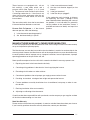
Figure 6. Burner Inspection
Burner
Flame
Manifold
of the furnace with no gaps, cracks, or sagging
between the furnace and fl oor or platform. The
return air and circulating air ductwork must
not be connected to any other heat producing
device such as a fi replace insert, stove, etc.
Doing so may result in fi re, explosion, personal
injury, carbon monoxide poisoning, or property
damage.
Use a type high velocity air fi lter in the return air
duct to maintain a clean heat exchanger.
WARNING:
Failure to prevent products of com-
bustion from being circulated into
the living space can create poten-
tially hazardous conditions includ-
ing carbon monoxide poisoning
that could result in personal injury
or death.
4. Vent System
The furnace must always be connected to
an approved vent pipe to carry the furnace
combustion products outdoors. At the beginning
and end of each heating season, inspect the
outdoor vent terminal closely with a fl ashlight to
determine if any of the conditions listed under
the following warning exist.
5. Maintenance
Proper maintenance is most important to
achieve the best performance from this furnace
and should be performed by a qualifi ed service
technician. Follow the maintenance schedule
(see Table 1) and the following instructions for
years of safe, trouble free operation.
• Do not place combustible materials on
or against the furnace cabinet.
• Do not store gasoline or any other
fl ammable vapors and liquids in the
vicinity of the furnace.
• Annually inspect the furnace, ductwork,
and vent system for signs of physical
deterioration.
• Change or replace the air fi lters monthly
during any period when the circulating
blower is operating regularly.
• Always replace the doors on the furnace
after servicing or cleaning/changing
the fi lters. Do not operate the furnace
without all doors and covers in place,
except to check burner operation.
• Avoid operating the furnace when
windows and doors are open.
• Be sure that the thermostat is properly
installed and is not being affected by
drafts or heat from lamps or other
appliances.
Air Filter(s) — Air fi lter(s) are not supplied
with the furnace as shipped from the factory.
The installer must provide a high velocity fi lter
and rack in the return air duct adjacent to the
furnace, or in a return air grille to the furnace.
The fi lter(s) must be removed and cleaned
monthly during the heating season to ensure
proper furnace operation. New or newly
renovated homes may require more frequent
changing until the construction dust has been
removed.
WARNING:
Never operate the furnace without
a fi lter in place. Dust and lint in the
return air can build up on the internal
components, resulting in a loss of
effi ciency, equipment damage, and
possible fi re.
Always replace the door(s) on the furnace after
servicing or cleaning/changing the fi lters. Do
not operate the furnace without the door(s) in
place.
Lubrication — The bearings in the circulating
air blower motors used in these furnaces are
pre-lubricated and sealed at the factory. No
further oiling of the bearings is required for the
life of the motor.

10
Blower Compartment — The blower
compartment should be inspected monthly
during the heating and cooling seasons and,
if needed, cleaned to remove any dirt and lint
that may have accumulated in the compartment
or on the blower and motor. Build-up of dirt
and lint on the blower and motor can create
excessive loads on the motor resulting in
higher than normal operating temperatures
and possible shortened service life.
Burner Maintenance — Check the burner
fl ames at the start of every heating season.
Set the thermostat to a temperature setting
above the room temperature. Remove the top
door from the furnace and visually inspect the
burner through the view hole to make sure that
the fl ame is drawn into the center of the heat
exchanger tube (See Figure 6). In a properly
adjusted burner assembly, the fl ame bends
down and to the right at the end of the heat
exchanger tube, and the end of the fl ame will
be out of sight around the bend. The fl ame
color should be blue, however some light
yellow streaks may occur on the outer portions
of the fl ame.
CAUTION:
Some components in the burner
vestibule are at high temperatures
while the burners are operating.
Use caution to avoid personal in-
jury.
WARNING:
Do not operate your furnace if you
fi nd any of the following conditions.
Such conditions may allow toxic
fumes to escape into your home:
• Obstructions or restrictions in the
vent pipe and/or chimney.
• Holes or cracks in the vent pipe.
• Visible corrosion in the vent pipe.
• Horizontal vent pipes that do not
slope upward.
If any of the above conditions
are found in the vent pipe, call
a qualifi ed service technician to
install new vent pipe.
For upfl ow and downfl ow low NOx models
only: Burner Maintenance, If the eighth
character of the model number is an “N” the
furnace has factory installed NOx reduction
inserts. The inserts reduce the NOx emissions
of the furnace. The NOx reduction inserts are
located in the fi rst pass of the top portion of
the heat exchanger. When the burners are
operating, the fl ame should extend through
the center of the NOx reduction inserts. The
fl ame color should be blue, however some light
yellow streaks may occur on the outer portions
of the fl ame.
Inspect the burners, mounting brackets, and
all other parts in the vestibule for signs of
deterioration. The burner vestibule should be
vacuumed clean and inspected annually.
CAUTION:
Do not strike any of the internal
electrical components while
vacuuming.
6. Operating Instructions
READ THE SAFETY INFORMATION ON THE
FOLLOWING PAGE BEFORE OPERATING.
WARNING:
Should overheating occur, or the
gas supply fail to shut off, shut off
the manual gas valve to the furnace
before shutting off the electrical
supply.
ADVERTISSEMENT:
En cas de température excessive,
ou s’il est impossible de couper
l’alimentation en gaz, fermer le
robinet manuel d’alimentation
en gaz du générateur d’air chaud
avant de couper l’alimentation
électrique.

11
These furnaces are equipped with roll-out
limit switch(s), a vent safety switch, and a
pressure switch (See Figures 1, 2, 3, 4 and
5). The pressure switch verifi es that the fl ame
is receiving combustion air. If the fl ame is not
drawn into the heat exchanger tube, the roll
out limit switch or fl ame sensor, will shut the
furnace down.
The vent safety switch shuts the furnace down
if the vent becomes blocked or restricted.
Furnace Fails To Operate — If the furnace
does not operate, check the following:
1) Is the thermostat operating properly?
2) Are the blower door(s) in place?
MANUFACTURER WARRANTY, OWNER RESPONSIBILITIES
It is the sole responsibility of the homeowner to make certain the gas furnace has been correctly
set up and adjusted to operate properly.
The Manufacturer warrants the furnace to be free from defects in material or workmanship for the
warranty period. However, the Manufacturer will not be responsible for any costs found necessary
to correct problems due to improper set-up, improper installation, furnace adjustments, improper
operating procedure on the part of the user, etc.
Some specifi c examples of service calls which cannot be included in warranty payments are:
1. Repairing duct work in the home found to be faulty.
2. Correcting wiring problems in the electrical circuit supplying the furnace.
3. Re-setting circuit breakers or other switches.
4. Correction of problems due to improper gas supply pressure to the furnace.
5. Providing instructional training on how to light and operate the furnace.
6. Furnace problems caused by installation of an air conditioner, heat pump, or other air com-
fort devices.
7. Revising installation of the vent assembly.
8. Adjusting or calibrating of the thermostat.
Carefully review these responsibilities with your dealer, service company, or gas supplier so there
will be no misunderstanding at a later time.
Read Your Warranty
Please read your limited warranty completely. It contains valuable information about your furnace.
If you have any questions about the warranty information, contact your distributor.
3) Is the furnace disconnect closed?
4) Has the circuit breaker tripped (or fuse
blown)?
5) Is the gas turned on?
6) Is the fi lter dirty or plugged?
If the combustion and circulating air blowers
are operating, and items 1 through 6 have
been checked without identifying the cause of
the problem, it is an indication of a potentially
serious problem in the installation. Contact a
qualifi ed serviceman to identify and repair the
problem.

708384A (Replaces 7083840)
Specifi cations and illustrations subject to change
without notice and without incurring obligations.
Printed in U.S.A. (01/07)
¢708384@¤
708384A
-
 1
1
-
 2
2
-
 3
3
-
 4
4
-
 5
5
-
 6
6
-
 7
7
-
 8
8
-
 9
9
-
 10
10
-
 11
11
-
 12
12


Broan FG6RA Manuel utilisateur
- Catégorie
- Cheminées
- Taper
- Manuel utilisateur
dans d''autres langues
- English: Broan FG6RA User manual
Documents connexes
-
Nordyne PGF1TA Manuel utilisateur
-
Kelvinator KG7SM054D-24B Manuel utilisateur
-
Maytag FG7S(C,L) Guide d'installation
-
Miller M4R(C,L) Manuel utilisateur
-
-
Kelvinator FG7S(A,K) Manuel utilisateur
-
Maytag PGC2TE - FS Guide d'installation
-
-
Kelvinator PGC2T(A,K) - FS Manuel utilisateur
-
Maytag KG7T(C,L) Guide d'installation