GE WX08X10025 Guide d'installation
- Catégorie
- Frigos
- Taper
- Guide d'installation

Side by Side Refrigerators
Design Guide
With Installation Instructions
Installation
Instructions
monogram.com

Safety Information
2
BEFORE YOU BEGIN
Read these instructions completely and carefully.
• IMPORTANT – Save these instructions for
local inspector’s use. Observe all governing codes
and ordinances.
• Note to Installer – Be sure to leave these
instructions with the Consumer.
• Note to Consumer – Keep these instructions with
your Owner’s Manual for future reference.
If you received a damaged refrigerator, you should
immediately contact your dealer or builder.
Skill Level – Installation of this refrigerator requires
basic mechanical, carpentry and plumbing skills.
Proper installation is the responsibility of the installer.
Product failure due to improper installation is not
covered under the GE Appliance Warranty.
See the Owner’s Manual for warranty information.
WARNING
Electrical Shock Hazard.
Plug into a grounded 3-prong outlet.
Do not remove the ground prong.
Do not use an adapter.
Immediately replace electric cords that become frayed
or damaged.
Do not use an extension cord with this appliance.
Failure to follow these instructions can result in death,
fire, or electrical shock.
Follow the instructions in the section Grounding the
Refrigerator.
This is the safety alert symbol. This symbol alerts you to potential hazards that can kill or hurt you and others.
All safety messages will follow the safety alert symbol and the word “DANGER”, “WARNING”, or “CAUTION”. These
words are defined as:
DANGER
Indicates a hazardous situation which, if not avoided, will result in death or serious injury.
WARNING
Indicates a hazardous situation which, if not avoided, could result in death or serious injury.
CAUTION
Indicates a hazardous situation which, if not avoided, could result in minor or moderate injury.
For Monogram local service in your area, call 1.800.432.2737.
For Monogram service in Canada, call 1.800.561.3344
For Monogram Parts and Accessories, call 1.877.959.8688.
www.monogram.com
WARNING
Tip Over Hazard.
These refrigerators are top heavy, especially with any doors open, and must be secured to prevent tipping
forward which could result in death or serious injury. Read and follow the entire installation instructions for
securing the refrigerator with the anti-tip system.
WARNING
Explosion Hazard.
Keep flammable materials and vapors, such as gasoline, away from refrigerator. Failure to do so can result in
fire, explosion, or death.
WARNING
To reduce the risk associated with choking, do not allow children under 3 years of age to have
access to small parts during the installation of this product.
CAUTION
Lifting Hazard
This refrigerator is very heavy. To reduce the risk of person injury during maneuvering and installing this
refrigerator, 3 people are required for proper installation of 36” wide model and 4 people are required for proper
installation of a 42” or 48” wide model.

AVERTISSEMENT
Risque de basculement
Ces réfrigérateurs présentent une partie supérieure lourde, en particulier avec une porte ouverte; ils doivent donc
être fixés pour prévenir le basculement vers l’avant et le risque concomitant de blessure grave ou fatale. Lisez et
suivez les instructions d’installation complètes pour l’installation du système anti-basculement.
AVERTISSEMENT
Risque d’explosion.
Conservez les matériaux et vapeurs inflammables tels que l’essence à l’écart de votre réfrigérateur. Le non-
respect de cette instruction peut entraîner un risque d’incendie, d’explosion ou de décès.
AVERTISSEMENT
Pour réduire le risque d’étouffement pendant l’installation de ce produit, ne pas laisser les
petites pièces à la portée des enfants âgés de moins de 3 ans.
ATTENTION
Risque associé à la manutention d’une charge lourde
Ce réfrigérateur est très lourd. Pour réduire le risque de blessure lors de la manutention de ce réfrigérateur, trois
(3) personnes sont nécessaires pour procéder à l’installation appropriée du modèle 36 pouces, quatre (4) pour
l’installation des modèles 42 ou 48 pouces.
Consignes de Sécurité
3
AVERTISSEMENT
Risque de choc électrique.
Branchez l’appareil dans une prise triple avec terre.
Ne retirez pas la broche de terre.
N’utilisez pas d’adaptateur.
Le non-respect de ces instructions peut entraîner des
risques d’incendies, des chocs électriques ou la mort.
Remplacer immédiatement tout cordon électrique
effiloché ou endommagé.
N’utilisez pas de rallonge avec cet appareil.
Le non-respect de ces instructions peut entraîner des
risques d’incendies, des chocs électriques ou la mort.
Suivez les instructions de la section Mise à la terre du
réfrigérateur.
Ce symbole représente une alerte de sécurité. Ce symbole vous avise de dangers possibles pouvant causer la mort, des
blessures ou autres. Tous les messages de sécurité seront précédés du symbole d’alerte de sécurité ainsi que des mots «
DANGER », « AVERTISSEMENT » ou « MISE EN GARDE ». Ces messages sont les suivants :
Signale une situation qui présente un danger imminent et qui, si elle n’est pas évitée, entraînera des bles
sures graves, voire la mort.
Signale une situation qui présente un danger imminent et qui, si elle n’est pas évitée, peut entraîner des
blessures graves, voire la mort. .
Signale une situation qui présente un danger imminent et qui, si elle n’est pas évitée, peut entraîner des
blessures mineures ou graves.
AVERTISSEMENT
DANGER
ATTENTION

4
Contents
Safety 2, 3
Instructions for Standard Installation 5-22
Planning Guide
The Installation Space 6
Dimensions and Clearances 6
Customization Basics 7
Side Panels 7
Refrigerator Location 7
1/4” Framed Panel Dimensions 8
3/4” Overlay Panel Dimensions 9
130° Door Swing 10
90° Door Swing 11
Dispenser Trim 12
Installation Instructions
Tools, Hardware, Materials 13
Grounding the Unit 13
Step 1. Remove Packaging 14
Step 2. Move the Refrigerator into the House 14
Step 3. Install Water Line 14
Step 4. Installation with Filtration System 15
Step 5. Install Side Panels 15
Step 6. Anti-Tip Procedures 15
Step 7. Level Refrigerator 16
Step 8. Alternate Anti-Tip Procedure 16
Step 9. Adjust Door Swing 17
Step 10. Install Grille Panel 17
Step 11. Install 1/4” Framed Panels 18
Step 11A. Install Overlay Panels 19, 20
Step 12. Connect Water Supply 20, 21
Step 13. Connect Power, Close Grille Panel 21
Step 14. Start Icemaker 21
Step 15. Install Toekick 21
Inspect Final Installation 22
Instructions for Flush Installation 23-40
Planning Guide
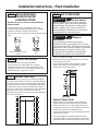
The Installation Space 24
Dimensions and Clearances 24
Customization Basics 25
Custom Handle Design Guide 25
Refrigerator Location 25
Side Panels 25
1/2” Overlay Panel Dimensions 26
3/4” Raised Panel Dimensions 27
3/4” Raised Door Panel Routing 28
3/4” Raised Grille Panel Routing 29
Dispenser Trim 30
Side Cleats 30
Installation Instructions
Tools, Hardware, Materials 31
Grounding the Unit 29
Step 1. Remove Packaging 32
Step 2. Move the Refrigerator into the House 32
Step 3. Install Water Line 32
Step 4. Installation with Water Filtration System 33
Step 5. Install Side Panels 33
Step 6. Install Case Trim 33
Step 7. Anti-Tip Procedure 33-34
Step 8. Level Refrigerator 34
Step 9. Adjust Door Swing 35
Step 10. Install Grille Panel 36
Step 11. Install 1/4” Framed Panels 37
Step 11A. Install Overlay Panels 38
Step 12. Connect Water Supply 39
Step 13. Connect Power, Close Grille Panel 39
Step 14. Start Icemaker 39
Step 15. Install Toekick 40
Inspect Final Installation 40
Instructions for Stainless Steel Installation 41-49
Planning Guide
The Installation Space 42
Dimensions and Clearances 42
Customization Basics 43
Side Panels 43
Refrigerator Location 43
130° Door Swing 44
90° Door Swing 45
Installation Instructions
Tools, Hardware, Materials 46
Grounding the Unit 46
Step 1. Remove Packaging 47
Step 2. Moving the Refrigerator into the House 47
Step 3. Install Water Line 47
Step 4. Installation with Water Filtration System 48
Step 5. Install Side Panels 48
Step 6. Anti-Tip Procedure 48
Step 7. Level Refrigerator 49
Step 8, Alternate Anti-Tip Procedure 49
Step 9. Adjust Door Swing 49
Step 10. Connect Water Supply 50
Step 11. Connect Power, Close Grille Panel 50
Step 12. Start Icemaker 50
Step 13. Install Toekick 51
Inspect Final Installation 51

Instructions for Standard Installation
5

B
A
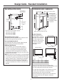
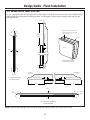
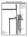
Design Guide - Standard Installation
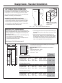
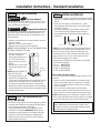
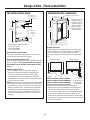
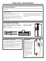
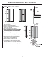
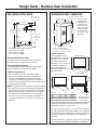
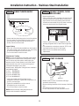
THE INSTALLATION SPACE
Water And Electrical Locations
The opening must be prepared with the electrical and
the cold water supply located as shown.
The Cutout Depth Must Be 24”
The refrigerator will project forward, slightly beyond
adjacent cabinetry for standard installation.
Additional Specifications
• A 115 volt 60Hz., 15 or 20 amp power supply is
required. An individual properly grounded branch
circuit or circuit breaker is recommended. Install
a properly grounded 3-prong electrical receptacle
recessed into the back wall. Electrical must be located
on the rear wall as shown.
NOTE: GFI (ground fault interrupter) is not recommended.
• The water line can enter the opening through the floor
or back wall. The water line should be 1/4” O.D. copper
tubing or SmartConnect
™
kit between the cold water
line and water connection location, long enough to
extend to the front of the refrigerator. Installation of
an easily accessible shut-off valve in the water line is
required.
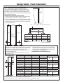
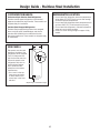
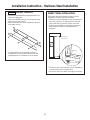
DIMENSIONS AND CLEARANCES
* Shipping height.
The refrigerator can
be adjusted to fit
into a cutout that
is 84-1/2” in height.
Use leveling legs
and wheels for a
maximum 1” height
adjustment.
Product Clearances
These refrigerators are
equipped with a 3-position
door stop. The factory-set
115° door swing can be
adjusted to 130°, or to 90°
if clearance to adjacent
cabinets or walls is
restricted.
6
90° Door Swing
130° Door Swing
115° Door Swing
*Finished Width
6"
5"
Electrical
Area
85" max
Finished
Opening
75" From Floor
to Bottom
of Electrical
Area
24"
5"
5"
3 1/2"
Water Supply
3 1/2"
36" Models 12"
42" Models 18"
48" Models 20"
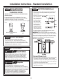
Allow minimum clearances for the freezer door
(Dimension A) and fresh food door (Dimension B) for a full
130° door swing and to allow for pan removal.
For a 90° door swing, allow 4” min. clearance to a wall.
If the 90° door stop position is used, pan access is
maintained, but pan removal is restricted.
See the illustrations on pages 10 and 11 to determine
door swing interaction with adjacent cabinets or
countertops.
Models A B C
36” 13” 15” 20-5/8”
42” 13” 19” 26-5/8”
48” 15” 20” 28-5/8”
*84"
From
Floor
25-3/8" Framed Models
Depth Including Handles 26-7/8”
36", 42" or 48"
Frame to Frame
35", 41", or 47"
Case Width
*83-1/2"
at
Rear
23-7/8"
Behind
Frame
C
*Min. Distance
to Wall
4”
B
A
*The finished cutout width must be:
35-1/2” for 36” models
41-1/2” for 42” models
47-1/2” for 48” models

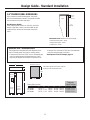
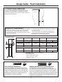
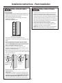
CUSTOMIZATION BASICS:
These refrigerators are designed to be customized with decorative panels. Field installed custom door and grille panels
are required.
7
Optional Accessory Kits
ZKHSS2: Monogram Tubular Stainless Steel handles
designed to fit 3/4” overlay panels.
ZKHPSS1: Professional Tubular Stainless Steel handles
designed to fit 3/4” overlay panels. Kit includes one handle.
Order 2 kits for side-by-side refrigerator models from your
Monogram supplier
Design Guide - Standard Installation
SIDE PANELS
Side panels must be used
whenever the sides of the
refrigerator will be exposed.
The 1/4” side panels will
slip into the side case trim.
Secure the panels to the
refrigerator with stick-on
hook and loop fastener
strips. Order the side
panels from the cabinet
manufacturer.
• Cut a notch in the top
front corner as shown
to allow clearance for
corner keys in the front
side trim.
* Depending on installation height.
*84"
2-9/16"
24"
*3" to 4"
3/16"
1-7/8"
REFRIGERATOR LOCATION
• Do not install the refrigerator where the temperature
will go below 55°F (13°C). It will not run often enough
to maintain proper temperatures.
• Do not install the refrigerator where temperatures will
go above 100°F (37°C). It will not perform properly.
• Do not install the refrigerator in a location exposed to
water (rain, etc.) or direct sunlight.
• Install it on a floor strong enough to support it fully
loaded.

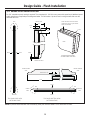
1/4” FRAMED PANEL DIMENSIONS
8
If you choose to install framed panels, they must
be cut to the dimensions shown. The panels will slide
into the frame on the door and grille.
Non-Dispenser Models
If the custom panel is less than 1/4” thick and it fits
loosely in the door frame it can be backed up with
a piece of filler material or foam tape to improve
the fit.
Fresh
Food
Panel
Freezer
Panel
E
D
F
G
A
B
Grille Panel
C
Dispenser
Cutout
9-5/8"
Dispenser Cutout
15-3/8
"
Side-by-Side (in inches)
A B C D E F G
36” Models 33-7/8 9 68-3/8 14-9/16 18-9/16 17-13/16 3-1/8
42” Models 39-7/8 9-1/2 68-3/8 14-9/16 24-9/16 17-13/16 3-1/8
48” Models 45-7/8 9-1/2 68-3/8 18-9/16 26-9/16 17-13/16 5-1/8
Dispenser
Cutout Position
IMPORTANT NOTE: Maximum total panel weight:
• Fresh food door panel – 75 lbs.
• Freezer door panel – 53 lbs.
• Grille Panel – 18 lbs.
1/4"
Panel
Door
5/16"
Trim
Reveal
The framed panel must be 1/4” nominal
thickness to fit the dispenser trim.
IMPORTANT NOTE – DISPENSER MODELS
The refrigerator is supplied with two dispenser trims,
one for framed panels and one for overlay panels.
• If the panel is less than 0.250” thick, a noticeable gap
may be created around the dispenser trim. Foam
tape may be applied on the door to improve the fit.
• If the panel is more than 0.250” thick, the dispenser
trim cannot be secured to the door.
See Dispenser Trim Fit Example, page 12.
Design Guide - Standard Installation

3/4” OVERLAY PANEL DIMENSIONS
For a more custom appearance, overlay panels may
be installed on trimmed models. The overlay panel must
be secured to a 1/4” thick backer panel which slides
into the trim. A spacer panel 0.10” thick must be placed
between the overlay and backer panel.
Assemble the panels with glue and screws:
• Center the spacer panel on the backer panel, left to
right and top to bottom. Secure the panels with glue.
• Center the spacer and backer panel on the overlay
panel and secure with glue and screws. Screws must
be countersunk into the backer panel.
NOTE: Left-to-right offset is
not always equal to top-to-
bottom offset.
9
Spacer Panel
Overlay Panel
Backer Panel
Fresh
Food
Panel
Freezer
Panel
E
D
F
G
A
B
Grille Panel
C
Dispenser
Cutout
9-5/8"
Dispenser Cutout
15-3/8
"
*Cut the dispenser opening after the backer, spacer and overlay
panels have been assembled.
36” Side-by-Side (in inches)
A B C D E F G
1/4” Backer Panel 33-7/8 9 68-3/8 14-9/16 18-9/16
.10” Spacer Panel 33 8-3/8 67 13-1/4 17-1/4
3/4” Overlay Panel 34-1/8 9-1/4 68-5/8 14-13/16 18-13/16 17-15/16 3-1/4
42” Side-by-Side (in inches)
A B C D E F G
1/4” Backer Panel 39-7/8 9-1/2 68-3/8 14-9/16 24-9/16
.10” Spacer Panel 39 8-5/8 67 13-1/4 23-1/4
3/4” Overlay Panel 40-1/8 9-3/4 68-5/8 14-13/16 24-13/16 17-15/16 3-1/4
48” Side-by-Side (in inches)
A B C D E F G
1/4” Backer Panel 45-7/8 9-1/2 68-3/8 18-9/16 26-9/16
.10” Spacer Panel 45 8-5/8 67 17-1/4 25-1/4
3/4” Overlay Panel 46-1/8 9-3/4 68-5/8 18-13/16 26-13/16 17-15/16 5-1/4
*Dispenser
Cutout Position
IMPORTANT NOTE: Maximum total weight for the assembled
panels:
• Fresh food door panel – 75 lbs.
• Freezer door panel – 53 lbs.
• Grille Panel – 18 lbs.
IMPORTANT NOTE – DISPENSER MODELS
The refrigerator is supplied with two dispenser trims,
one for framed panels and one for overlay panels. The
overlay dispenser trim is designed to fit a total panel
thickness of 1.100”.
• If the panel is less than 1.100” a noticeable gap may
be created around the dispenser trim.
• If the panel is more than 1.100” the dispenser trim
cannot be secured to the door.
See Dispenser Trim Fit Example, page 12.
.250” + .10” + .750” = 1.100” Total Panel Thickness
• The overlay panel must be constructed according to
the specifications shown to achieve the correct total
thickness.
• Alternative panel construction methods such as
securing a 3/4” panel to a 1/4” backer panel cannot
be used. Another method, routing a 3/4” thick panel
on all sides, cannot be used. These methods will not
result in the required 1.100” panel thickness.
3/4"
Overlay
Panel
1/4"
Backer
Panel
Door
.10"
Spacer
Design Guide - Standard Installation

10
Design Guide - Standard Installation
1/4"
1/2"
3/4"
1"
1-1/4"
1"
3/4" Overlay
Panel
(Nominal Size)
Stainless Steel
1/4"
1/2"
3/4"
2"
1-1/4"
1-1/2"
1-3/4"
3"
2-1/4"
2-1/2"
2-3/4"
1/4"
1/2"
3/4"
Door
23-7/8" From
Rear of
Refrigerator
1"
Refrigerator
Case
Trim
Top View
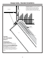
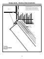
130° DOOR SWING
Scale 1:1
IMPORTANT NOTE –
FOR DISPENSER MODELS:
Dispenser models are supplied with two
dispenser trims, one to fit framed panels
and one for overlay panels. Dispenser trim
fit to the custom panel depends on correct
panel thickness. Framed panels must be
1/4” nominal. Overlay panels should be
constructed as shown to accomplish a total
1.100” thickness. See pages 19 and 20 for
details.
Frameless Cabinets: The case trim overlaps
cabinets at the top and sides. Therefore,
frameless cabinets may require filler strips
to prevent interfeence with cabinet door
swing. The opening must allow for filler strips.

1/4"
1/2"
3/4"
1"
1-1/4"
1/4"
1/2"
3/4"
1"
1-1/4"
1-1/2"
23-7/8"
From Rear of
Refrigerator
3/4" Overlay
Panel
(Nominal Size)
Case Trim
Refrigerator
Door
Stainless Steel
Top View
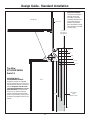
90° DOOR SWING
Scale 1:1
IMPORTANT NOTE –
FOR DISPENSER MODELS:
Dispenser models are supplied
with two dispenser trims, one to fit
framed panels and one for overlay
panels. Dispenser trim fit to the
custom panel depends on correct
panel thickness. Framed panels
must be 1/4” nominal. Overlay
panels should be constructed as
shown to accomplish a total 1.100”
thickness. See pages 19 and 20 for
details.
Frameless Cabinets:
The case trim overlaps
cabinets at the top
and sides. Therefore,
frameless cabinets may
require filler strips to
prevent interference
with cabinet door swing.
The opening must allow
for filler strips.
Design Guide - Standard Installation
11

12
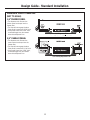
DISPENSER TRIM FIT EXAMPLES:
(NOT TO SCALE)
1/4” FRAMED PANEL
• The dispenser trim fits over the
custom panel and snaps into the
freezer door.
• The clips will not engage the door
if the panel is more than 0.250” thick.
• If the panel is less than 0.250” thick,
a noticeable gap may be created
around the dispenser trim.
3/4” OVERLAY PANEL
• The dispenser trim fits over the
custom panel and snaps into the
freezer door.
• The clips will not engage the door
if the panel is more than 1.100” thick.
• If the panel is less than 1.100” thick,
a noticeable gap may be created
around the dispenser trim.
Design Guide - Standard Installation
1/4” Dispenser Trim
3/4” Overlay Dispenser Trim

13
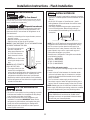
TOOLS AND MATERIALS REQUIRED
• Tinsnips to cut banding
• Stepladder
• 1” Bit extension
• Tape measure
• Gloves
• 1/4” Drywall screws
• 5-Gal. Bucket with cover
• 6” Spirit level
• Appliance hand truck
• Tubing cutter
• 7/16” open-end wrench
• #2 Phillips screwdriver
• Drill and appropriate bits
• 5/16”, 7/16” socket
• Safety glasses
• 1-1/8” open end wrench
• Pliers
• 1/4”, 5/16” Combo Rachet
• 35” long 2x4 for Anti-Tip support
• 1/4” copper water line tubing or SmartConnect
™
Refrigerator Tubing kits
• Water shut-off valve
• Custom panels for doors and grille panel
• Screws to secure refrigerator to cabinetry
• Stick-on hook and loop fastener strips for
1/4” side panels
Installation Instructions - Standard Installation
HARDWARE SUPPLIED
• Water filter bypass plug
• Toekick
• 1/4” nut and ferrule
• Dispenser trim for overlay panels (for use with
Custom Panel models).
GROUNDING THE REFRIGERATOR
WARNING
Electrical Shock Hazard.
Failure to follow these instructions can result in death,
fire, or electrical shock.
The power cord of this appliance is equipped
with a 3-prong (grounding) plug which mates
with a standard 3-prong (grounding) wall receptacle
to minimize the possibility of electric shock hazard
from this appliance.
Have the wall outlet and circuit checked by a qualified
electrician to make sure the outlet is properly
grounded.
Where a standard 2-prong wall outlet is encountered,
it is your personal responsibility and obligation to have
it replaced with a properly grounded 3-prong wall
outlet.
DO NOT, UNDER ANY
CIRCUMSTANCES, CUT OR
REMOVE THE THIRD (GROUND)
PRONG FROM THE POWER CORD.
DO NOT USE AN ADAPTER PLUG TO CONNECT
THE REFRIGERATOR TO A 2-PRONG OUTLET.
DO NOT USE AN EXTENSION CORD WITH THIS
APPLIANCE.
MISE À LA TERRE DU RÉFRIGÉRATEUR
AVERTISSEMENT
Risque de choc électrique.
Le non-respect de ces instructions peut entraîner des
risques d’incendies, des chocs électriques ou la mort.
Le cordon d’alimentation de cet appareil est équipé
d’une fiche à trois broches (pour une mise à la terre)
qui s’adapte à la prise de courant standard à 3
broches (pour une mise à la terre) pour minimiser les
risques de chocs électriques par cet appareil.
Faites vérifier la prise murale et le circuit électrique par
un électricien qualifié pour s’assurer que le système est
correctement mis à la terre.
Dans le cas d’une prise biphasée, l’installateur a la
responsabilité et l’obligation de la remplacer par une
prise triphasée correctement mise à la terre.
NE COUPEZ PAS OU N’ENLEVEZ
PAS, SOUS AUCUN PRÉTEXTE,
LA TROISIÈME BROCHE DE
MISE À LA TERRE DU CORDON
D’ALIMENTATION.
N’UTILISEZ PAS D’ADAPTATEUR
POUR BRANCHER LE
RÉFRIGÉRATEUR À UNE PRISE BIPHASÉE.
N’UTILISEZ PAS DE RALLONGE AVEC CET APPAREIL.
FLOORING
For proper installation, this refrigerator must be placed
on a level surface of hard material that is at the same
height as the rest of the flooring. This surface should
be strong enough to support a fully loaded refrigerator,
or approximately 1,500 lbs.
NOTE: Protect the finish of the flooring. Cut a large
section of the cardboard carton and place under
the refrigerator where you are working.

Installation Instructions - Standard Installation
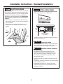
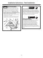
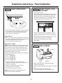
STEP 1 REMOVE PACKAGING
WARNING
Tip Over Hazard.
The refrigerator is much heavier at the top than at the
ERWWRP³EHFDUHIXOZKHQPRYLQJ:KHQXVLQJDKDQG
truck, handle from the side only.
AVERTISSEMENT
Risque de basculement
Le réfrigérateur est beaucoup plus lourd en haut qu’en
bas. Il faut être prudent lors des déplacements. Si un
diable est utilisé, il faut soulever le réfrigérateur sur le
côté seulement.
• Carefully cut banding at the top and bottom, remove
the outer carton.
• Slide out the back corner posts (2).
• Slide the carton off the top of the cabinet.
NOTE: IT IS NOT NECESSARY TO LAY THE CABINET DOWN
IN ORDER TO REMOVE THE SKID!
• The unit is secured to the
skid with 4 slotted tie-
down straps. Remove the
six 7/16” bolts from the
base channels in the tie-
downs.
• Remove the six 7/16” bolts
securing the straps to the
skid.
NOTE: DO NOT ATTEMPT TO
ROLL UNIT OFF SKID.
• The support blocks on the
bottom of the refrigeration
case must be removed before the refrigerator is taken
off the skid or damage will occur. Carefully tilt the
refrigerator and slide the blocks out from beneath.
• Remove the toekick and set aside for final installation.
• Lift the refrigerator off the skid with an appliance dolly.
Handle from the sides.
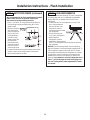
STEP 3 INSTALL WATER LINE
• A cold water supply is required for automatic icemaker
operation. The water pressure must be between 40 and
120 p.s.i.
• Route 1/4” OD copper or SmartConnect
™
plastic
tubing between house cold water line and the water
connection location.
• The tubing should be long enough to extend to the
front of the refrigerator. Allow enough tubing to
accommodate the bend leading into the water line
connection.
14
Remove
Tie Downs
Toekick
Floor
Cold Water Line
NOTE: The only GE Appliances approved plastic tubing
is supplied in the SmartConnect
™
Refrigerator Tubing
kits. Do not use any other plastic water supply line
because the line is under pressure at all times. Other
types of plastic may crack or rupture with age and
cause water damage to your home.
SmartConnect
™
Refrigerator Tubing Kits are available
in the following lengths:
2’ (.6 m) WX08X10002
8’ (2.4 m) WX08X10006
15’ (4.6 m) WX08X10015
25’ (7.6 m) WX08X10025
STEP 2 MOVE THE REFRIGERATOR
INTO THE HOUSE
• Re-use the corner posts from the packaging to protect
stainless steel models. Run the appliance dolly straps
over the posts and under the handles.
• Leave the protective film on the refrigerator until
installation is complete. IMPORTANT: Never lift the
refrigerator by the handle or push against the grille
panel; this could cause damage or misalignment.
• Avoid laying the unit on its back or side to prevent
sealed system restrictions.
NOTE: Commonwealth of Massachusetts Plumbing
Codes 248CMR shall be adhered to. Saddle valves
are illegal and use is not permitted in Massachusetts.
Consult with your licensed plumber.
Shut off the main water supply.
Turn on the nearest faucet long enough to clear the line
of water.
• Install a shut-off valve between the icemaker water
valve and cold water pipe in a basement or cabinet.
The shut-off valve should be located where it will be
easily accessible.
• Turn on the main water supply and flush debris.
Run about a quart of water through the tubing into a
bucket. Shut off the water supply at the shut-off valve.
NOTE: Saddle type shut-off valves are included in many
water supply kits. Before purchasing, make sure a saddle
type valve complies with your local plumbing codes.

15
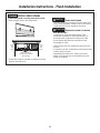
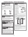
STEP 4 INSTALLATION WITH
HOUSEHOLD WATER
FILTRATION SYSTEM
Skip this step if you do not have a household water
filtration system
If the water supply to the refrigerator is from any
household water filtration system, the filter cartridge
should be removed. For better ice and water
performance, remove the filter and install the filter bypass
plug.
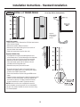
STEP 5 INSTALL SIDE PANELS
Skip this step when not using side panels.
If you are using 1/4” side panels, they should be
inserted into the case trim. Fasten the panels to the
refrigerator with stick-on hook and loop fastener strips
before setting the refrigerator in place.
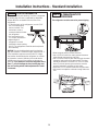
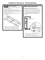
STEP 6
ANIT-TIP PROCEDURE
WARNING
Tip Over Hazard.
These refrigerators are top heavy, especially
with any doors open, and must be secured to
prevent tipping forward which could result in
death or serious injury. Read and follow the
entire installation instructions for securing the
refrigerator with the anti-tip system.
AVERTISSEMENT
Risque de
basculement
Ces réfrigérateurs présentent une partie
supérieure lourde, en particulier avec une porte
ouverte; ils doivent donc être fixés pour prévenir le
basculement vers l’avant et le risque concomitant
de blessure grave ou fatale. Lisez et suivez
les instructions d’installation complètes pour
l’installation du système anti-basculement.
Installation Instructions - Standard Installation
Filter Bypass
Plug
Rotate Counterclockwise To
Remove
• Cut a 2” x 4” block, 35” long and secure the block to
the mounting brackets provided using #12 or #14
wood screws.
• Secure the bracket
with wood block
to the back wall so
that it is 84” from
the finished floor.
Use #12 or #14
wood screws. See
the illustration.
• The screws must
penetrate at least
one inch into the
vertical wall studs.
• If metal wall studs, use self-tapping sheet metal
screws in place of wood screws.
IMPORTANT: When the refrigerator is installed under
a soffit or if there is not enough height for this method
of security, brackets cannot be used. Proceed to step
7 to level the refrigerator and then to step 8 to secure
refrigerator to cabinets. The refrigerator must be
secured to prevent tipping.
Connect Power Cord:
• Before pushing the refrigerator into the opening, plug
the power cord into the receptacle. Open the grille
panel and reach into the opening at the back to grasp
the power cord. Pull the power cord into the opening
as you push the refrigerator back.
• Gently push refrigerator into the opening with hands
against front corners.
STEP 6
ANIT-TIP PROCEDURE (Cont.)

16
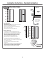
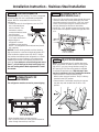
STEP 7 LEVEL REFRIGERATOR
All models have 4-point leveling. The front is supported
by leveling legs, the rear is supported by adjustable
wheels. Both are accessible from the front of the
refrigerator.
• To level the back of the refrigerator, turn the 7/16”
hex nut located above
the front wheels. Turn
clockwise to raise or
counterclockwise to lower
the refrigerator.
• For front leveling, use a
1-1/4” open-end wrench.
• Adjust height of
refrigerator to match
installation cutout opening
84-1/2”. The refrigerator should be level and plumb
with
cabinetry
.
NOTICE: The rear leveling wheels and front leveling
legs are limited to a maximum height adjustment of 1”.
If the installation requires more than 84-1/2” height,
the installer should elevate the refrigerator on a sheet
of plywood or runners. Cabinetry trim could also be
added across the top of the opening to shorten the
opening. If you attempt to raise the refrigerator more
than 1”, you will damage the front leveling legs and
the rear leveling wheels. Make adjustments in small
increments.
Installation Instructions - Standard Installation
STEP 8 ALTERNATE ANTI-TIP
PROCEDURE
The refrigerator must be secured to prevent tipping.
• Raise the grille panel to access case trim.
• Use a 3/16” bit to drill four evenly spaced clearance
holes through the metal top case trim.
• Use a 1/16” bit to drill to pilot holes through the metal
clearance holes and into the wood soffit. The holes
should be centered in the soffit or a 3/4” min. wood
brace. The brace spanning the enclosure must be
securely fastened to cabinets on both sides.
• Install four, 1-1/2” drywall screws into the pilot holes.
• Drill screws into adjacent cabinets through side case
trim.

Installation Instructions - Standard Installation
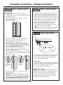
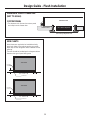
STEP 9 ADJUST DOOR SWING
NOTE: This refrigerator has a 3-position door stop: 90°,
115°, and 130°. When space does not allow the door
to swing open fully to 115°, you may change the door
swing to a 90° opening. A 130° door swing option is
available for standard installation only. Skip this step
if door opening is satisfactory for your installation
situation.
• Open the door to view the bottom hinge. Note the
door stop pin locations. The pin is factory installed in
the 115° position.
• Close the door. From below, use pliers to unscrew
the door stop and reinstall into the 130° or 90°
position.
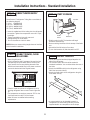
STEP 10 INSTALL GRILLE PANEL
To insert the framed or overlay panel into the grille:
• Raise the grille panel to the stop position.
• Loosen the screws on the side trim behind the frame.
Remove the bottom trim.
Adjust Nut Below
Spring to Accommodate
Panel Weight
Loosen
Side
Trim
Screw
Loosen
Side
Trim
Screw
CAUTION
SHARP EDGE HAZARD
The metal panel may be slippery. Grip the metal panel
firmly so the panel does not slip out of the frame and
cause personal injury or damage to the frame.
ATTENTION
RISQUE DE COUPURE : ATTENTION
AUX ARÊTES VIVES
Le panneau en métal peut bêtre glissant. Tenir
fermement le panneau en métal, de manière à ce
que le panneau ne glisse pas en dehors du cadre
en provoquant des blessures corporelles ou des
dommages au cadre.
• Slide the panel over the metal backer panel and into
the trim.
• If necessary, tap with a wood block until the panel slips
under the top trim piece.
• Reassemble the bottom trim. Tighten the screws.
• Adjust the hinge spring to accommodate the panel
weight, if necessary.
17

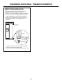
STEP 11 INSTALL 1/4” FRAMED PANELS
Install door panels:
• Open the door to 90°. Remove the 6 Phillips head screws
from the door handle.
• Remove the handle. Retain all screws.
• Remove the 6 screws holding the trim, then lift off
the trim. Retain the screws.
• Slide the framed panel into the door trim.
Dispenser Models Only:
• The dispenser controls protrude beyond the face
of the freezer door. To avoid damage to the dispenser,
the trim at the top of the door should be removed.
• Remove the screws holding the top trim in place.
• Place the freezer panel into the bottom channel
and slide into the hinge side trim.
• Reinstall the top trim piece with screws.
• There are two sets of holes in the handle side trim.
Replace the handle side trim by installing the original
screws in the FRONT screw holes.
• Secure the handle to the door using the REAR screw
holes.
• Follow the same procedures to install the opposite panel.
• Check to be sure the handles are evenly aligned with
each other at the top. To adjust, loosen the handle
screws and slide up or down. Tighten the screws.
NOTE: Aluminum cover trim is supplied for use with
custom handles on overlay panels. It is not intended for
use with 1/4” panels. Discard the cover trim when using
1/4” framed panels.
Go to Step 12A for Overlay Panels
Supplied
Handle Shown
in 1/4” Panel
Position
18
Installation Instructions - Standard Installation

STEP 11A INSTALL OVERLAY PANELS
Install door panels:
• Open door to 90°. Remove the 6 Phillips head screws
from the door handle.
• Remove the handle. Retain all screws.
• Remove the 6 screws holding the trim, then lift off
the trim. Retain the screws.
• Slide the overlay panel into the door trim.
Dispenser Models Only:
• The dispenser controls protrude beyond the face
of the freezer door. To avoid damage to the dispenser,
the trim at the top of the door should be removed.
• Remove the screws holding the top trim in place.
• Place the assembled freezer panel into the bottom
channel and slide into the hinge side trim.
• Reinstall the top trim piece with the screws.
• There are two sets of holes in the handle side trim.
Replace handle side trim by installing the original screws
in the REAR screw holes.
• Secure the handle to the door using the FRONT
screw holes.
• Follow the same procedures to install the opposite panel.
• Check to be sure the handles are evenly aligned with
each other at the top. To adjust, loosen the handle
screws and slide up or down. Tighten the screws.
Supplied Handle
Shown in Overlay
Panel Position
Installation Instructions - Standard Installation
19

STEP 12 CONNECT WATER SUPPLY
• Locate and bring the tubing to the front of the cabinet.
• Turn the water on to flush debris from the line. Run
about a quart of water through the tubing into a
bucket, then shut off the water.
Copper Tubing:
• Slip a 1/4” nut and ferrule (provided) over both ends of
the copper tubing. Insert the tube into the union fitting
on the unit and tighten the nut to the union.
• Turn on the water to check for leaks.
SmartConnect
™
Tubing:
NOTE: The only GE Appliances-approved plastic tubing
is supplied in the SmartConnect
™
Refrigerator Tubing
kits. Do not use any other plastic water supply line
because the line is under pressure at all times. Other
types of plastic may crack or rupture with age and
cause water damage to your home.
Refrigerator
Water Supply
House
Water Supply
20
Installation Instructions - Standard Installation
STEP 11A INSTALL OVERLAY PANELS
(continued)
Custom Handles
• If you are using custom handles, the handle must
be properly secured to the overlay panel before sliding
the panel into the trim.
• The cabinet manufacturer will supply the custom
handle and hardware.
• Discard the supplied handle.
• Remove the trim. Peel away a few inches of the
adhesive backing.
IMPORTANT: The tape is very sticky and strong. Once
it adheres to a surface, it cannot be removed without
damaging both surfaces. Do not install the trim before
the final wood panels are in place. Be sure to align
the trim carefully before removing the paper backing.
Reinstall all original screws.
• Reinstall the handle side trim, using all 12 supplied
flat-head screws, plus the 12 flat-head screws
originally installed in the handle trim.
• Install a supplied end cap onto the top of the door,
using a Phillips head screwdriver and the 2 screws
provided. Hand-tighten the screws into the end caps.
Do not overtighten; damage will occur.
&OHDQWKHDOXPLQXPWULPZLWKUXEELQJDOFRKRO³
do not use alcohols with oil or lanolin that will prevent
adhesion of double-sided tape.
• Slip the aluminum cover onto the top bracket to check
the fit. The aluminum cover trim has a slot on each end
which fits the bracket.
Secure top
bracket with
2 screws.
Top Bracket
Top Bracket
STEP 11A INSTALL OVERLAY PANELS
(continued)
• Carefully place the aluminum cover trim onto the top
bracket so that the bracket is inside the cover trim.
Use the top to bottom grooves along the handle side
to align the cover trim accurately. Align the bracket with
the screw holes in the top of the door. Pull the tape a
few inches at a time while pressing the trim against
the door. Press and hold approximately 10 seconds
before continuing along the length of the door.
• Install another bracket at the bottom of the door
to secure the cover trim. Use a stubby Phillips head
screwdriver and the 2 screws provided.
• NOTE: Make sure there are no gaps in the installation.
• Follow the same procedure on the opposite door.
Slide aliminum
trim over top
bracket.
La page est en cours de chargement...
La page est en cours de chargement...
La page est en cours de chargement...
La page est en cours de chargement...
La page est en cours de chargement...
La page est en cours de chargement...
La page est en cours de chargement...
La page est en cours de chargement...
La page est en cours de chargement...
La page est en cours de chargement...
La page est en cours de chargement...
La page est en cours de chargement...
La page est en cours de chargement...
La page est en cours de chargement...
La page est en cours de chargement...
La page est en cours de chargement...
La page est en cours de chargement...
La page est en cours de chargement...
La page est en cours de chargement...
La page est en cours de chargement...
La page est en cours de chargement...
La page est en cours de chargement...
La page est en cours de chargement...
La page est en cours de chargement...
La page est en cours de chargement...
La page est en cours de chargement...
La page est en cours de chargement...
La page est en cours de chargement...
La page est en cours de chargement...
La page est en cours de chargement...
La page est en cours de chargement...
La page est en cours de chargement...
La page est en cours de chargement...
La page est en cours de chargement...
-
 1
1
-
 2
2
-
 3
3
-
 4
4
-
 5
5
-
 6
6
-
 7
7
-
 8
8
-
 9
9
-
 10
10
-
 11
11
-
 12
12
-
 13
13
-
 14
14
-
 15
15
-
 16
16
-
 17
17
-
 18
18
-
 19
19
-
 20
20
-
 21
21
-
 22
22
-
 23
23
-
 24
24
-
 25
25
-
 26
26
-
 27
27
-
 28
28
-
 29
29
-
 30
30
-
 31
31
-
 32
32
-
 33
33
-
 34
34
-
 35
35
-
 36
36
-
 37
37
-
 38
38
-
 39
39
-
 40
40
-
 41
41
-
 42
42
-
 43
43
-
 44
44
-
 45
45
-
 46
46
-
 47
47
-
 48
48
-
 49
49
-
 50
50
-
 51
51
-
 52
52
-
 53
53
-
 54
54


GE WX08X10025 Guide d'installation
- Catégorie
- Frigos
- Taper
- Guide d'installation
dans d''autres langues
- English: GE WX08X10025 Installation guide
Documents connexes
Autres documents
-
Monogram ZISS480NHSS Guide d'installation
-
 GE Monogram ZIPS360NHSS Guide d'installation
-
Signature Kitchen Suite SKSFD3604P Guide d'installation
-
 GE Monogram ZIRS360NBRH Guide d'installation
-
-
-
 GE Monogram ZIFP360NHLH Guide d'installation
-
 GE Monogram ZIF360NHRH Guide d'installation
-
-
Liebherr HC1540 Guide d'installation


