Carrier 40BNE018-036 Le manuel du propriétaire
- Catégorie
- Climatiseurs split-system
- Taper
- Le manuel du propriétaire

OWNER'S MANUAL
38BNB BNE018-036
40BNB BNE018-036
Cooling Only and Heat Pump Duct-Free High Wall Systems
iill
CONTENTS
Page
INTRODUCTION ................................. 2
GENERAL ....................................... 2,3
OPERATING MODES ............................ 2
REMOTE CONTROL ............................. 2
OPERATION ................................... 3-7
REMOTE CONTROL OPERATION ................ 3
UNIT OPERATION ............................... 7
(;LEANING AND MAINTENANCE ............... 8,9
AIR FILTERS .................................... 8
Page
INDOOR UNIT FRONT PANEL ................... 8
INDOOR UNIT COIL ............................ 8
OUTDOOR UNIT COIL .......................... 8
CONDENSATE DRAINS ......................... 8
SYSTEM OPERATION CHECK LIST .............. 9
DIP SWITCH SETTINGS ......................... 9
ENERGY SAVING RECOMMENDATIONS ......... 9
TROUBLESHOOTING GUIDE ................ 10-12
Manufacturer reserves the right to discontinue, or change at any time, specifications or designs without notice and without incurring obligations.
PC 111 Catalog No. 533-80098 Printed in U.S,A, Form OM38/40-4 Pg 1 4-03 Replaces: New

INTRODUCTION
Thank you for choosing a Stremnline,Cr9Duct Free System.
The stone pride in craftsmanship and engineering knowledge
that goes into equipment cooling the Astrodome in Texas, the
Sistine Chapel in Rome, the U.S. Capitol Hall of Confess, and
thousands of other installations worldwide has gone into the
construction of this unit.
Duct Free Systems provide quiet, maximum comfort. In ad-
dition to cooling and/or heating, the Duct Free System will tit-
ter and dehumidify the air in the room to provide maximum
comfort.
IMPORTANT: Duct Free Systems should be installed by
authorized personnel only, using approved tubing and
accessories. If technical assistance, service oi repair is
needed, contact the installer or call 1-800-227-7437.
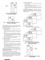
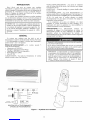
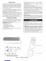
GENERAL
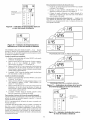
The Duct Free System can be set up and operated tiom the
relnote control (provided). See Fig. 1. If the remote is mis-
placed, the system can be operated t_romthe "Auto" setting on
the unit.
Operating Modes -- The duct tiee system has 5 operat-
ing modes:
• Cooling
• Fan Only
• Heating (if applicable)
• Dehmnidification
• Auto
COOLING In Cooling mode, the system cools, dries and
filtersroom air.
FAN ONLY In Fan Only mode, the system filters and cir-
culates room air without chanNng room air temperature.
HEATING In Heating mode, the system heats and filters
roolTl air.
DEHUMIDIFICATION In Dehmnidification mode, the
system dries, filters and slightly cools room air temperature.
This mode does not take the place of a dehumidifier.
AUTO In Auto mode, the system wilt automatically cool or
heat room air according to a selected temperature (set point).
If temperature of room air is lower than set point, the system
will operate in Heating mode. If temperature of room air is
higher than set point, the system will operate in Cooling mode.
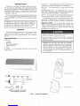
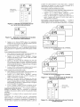
Remote Control -- The remote controltranslnitscom-
mandsto set up and operate the system. The controller has a
window display panel that shows the current system status. The
controller can be secured to a surface when used with the
mounting rack provided. See Fig. 1.
Handle the controller with care and avoid getting the con-
troller wet. Damage to the device may result.
Do not leave remote control in a drawer ornear a warm!hot
appliance as the system will try to cool the environment
around the controller.
IMPORTANT: The remote control and unit continually
exchange information regarding room air temperature.
When operating the remote control tiom the mounting
rack, be sure there is a direct line of sight between the
controller and the unit. The controller can operate the
unit tiom a distance ofup to 23 ft as long as there are not
any obstructions.
B 0
UP/DOWN {i_) HEATING FUNCTION
BUTTON
_?i _,DRY @ HIGH
DOWN g) AUTO _ AUTO
REMOTE CONTROL BUTTONS --
PROGRAMMING OPTIONS
Fig. 1 -- Duct Free System
REMOTECONTROL
MOUNTING RACK

The relnote control can perform the following functions:
• Turn the system ON and OFF
• Select operating mode
• Adjust room air temperature and tan speed
• Set time periods for automatic system operation
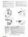
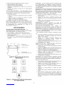
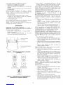
BATTERY INSTALLATION Two AAA 1.5V alkaline
batteries (included) are required for operation of the relnote
control. See Fig. 2 for battery location.
To install batteries:
1. Remove battery compartlnent cover by sliding off of
relnote.
2. Insert batteries being sure to follow polmity markings in-
side battery compartlnent.
3. Replace battery compartlnent cover.
NOTE: Replace batteries whenever "Low battery" iMicator
appears on remote control display panel.
DISPLAY SCREEN There are five operating mode indica-
tors that appear on the rcnnotecontrol display screen. See Fig. 3.
OPERATION
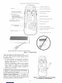
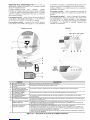
Remote Control Operation-- The remote control
has 3 buttons (see Fig. 4) used for operating and controlling the
system:
• MODE button changes operating mode
• UP/DOWN button selects desired operating mode
• ON/OFF button turns the system on or off and trans-
mits programing selections to unit.
BACK OF
REMOTE CONTROL
2 AAA 1,5V BATTERIES
BATTERY COMPARTMENT
COVER
Fig. 2 -- Location of Batteries on Remote Control
COOLING
FAN ONLY
\\1 I//
HEATING
83
DEHUMIDIFICATION
AUTO
Fig. 3-- Operating Mode Indicators on
Remote Control
NOTE: When transmitting a colrnnand fiom the controller to
the unit, be sure to point the controller toward the right side of
the unit. See Fig. 4. The unit will confirm receipt of a com-
mand by sounding 2 audible beeps.
IMPORTANT: If no changes are made within 10 sec- ]
onds, the remote control will remm to its previous I
setting.
FAN SPEED To select the Fan mode and change the Fan
Speed, follow the steps below:
1. Press MODE button to select the Fan mode.
2. Press UP/DOWN button to select desired tan speed or
to Auto.
3. Press ON/OFF button to send changes to unit from re-
mote control.
NOTE: If unit is operating in DEtRIMIDIFICATION mode
the l_anwill only operate in Low speed and cannot be changed.
TEMPERATURE SETTINGS The temperature settings
can be easily changed by pointing the controller toward the unit
and pressing the UP/DOWN button until desired temperature
appears on screen. The _' symbol appears each time the ON/
OFF button is pressed.
Another way of changing the temperature is as follows:
1. Select the temperature display by pressing the MODE
button. The degee symbol will flash next to the digits on
the screen.
2. Press UP/DOW2"_button to select the desired tempera-
ture. The available temperature range is fiom 54 F to
90 F.
3. Press ON/OFF button to send changes to unit fiom re-
mote control.
AIRFLOW DIRECTION Perform the following steps to
change the direction of airflow from the unit:
1. Press MODE button to select the Sweep fanction.
2. Press the top of the UP/DOWN button to move the air
deflector on the unit in an up and do,a_ motion. The air-
flow symbol displays motion.
3. Press the bottom of the UP/DOWN button. The airflow
deflector stops at a given angle. The airflow symbol dis-
play remains in a fixed position.
4. Press ON/OFF button to seM changes to unit fiom re-
mote control.
NOTE: If placing the air deflector in a fixed position is chosen,
the deflector stops at the angle in which it was located when
the ON/OFF button was pressed.
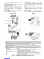
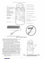
SETTING CLOCK
1. Slide down fiont cover of controller below ON/OFF but-
ton. See Fig. 4.
2. Press CLOCK button using the tip of a pen or paper clip.
See Fig. 5.
3. Press UP/DOWN button to set minutes.
4. Press MODE button. The hour digits will flash.
5. Press to UP/DOWN button to set the hour.
6. To confirm cunent clock settings, press CLOCK button
once again using the tip of a pen or paper clip. The remote
control will automatically go back to previous display
and the clock is displayed.

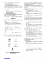
INFRARED SIGNAL TRANSMITTER WINDOW
CLOCK
TI MER START/STO P
ONE-TIME/DAILY INDICATORS
MODE BUTTON
OPERATION MODE INDICATORS -
COOLING, FAN, HEATING,
DEHUMIDIFICATION AUTO
FAN INDICATORS -
LOW, MEDIUM, HIGH, AUTO
TIMER SET BUTTONS*
SLIDE DOWN PANEL i
SENSOR
INDICATOR
-- LOW BATTERY INDICATOR
UP/DOWN BUTTON
SENSOR ACTIVE INDICATOR
SWEEP INDICATOR
ON/OFF BUTTON
ROOM TEMPERATURE BUTTON*
BUTTON*
LOCAL SENSING BUTTON*
*Buttons located behind slide down panel.
Fig. 4- Remote Control
PROGRAMMING TIME PERIODS The duct t}ee sys-
tem can be pr%malrnned to operate at desired levels. Be sure to
set the clock before promalrnning the system.
• Increments of time are in 10-minute intervals.
• The Timer Start/Stop indicator light on the unit is on
when a time period is set. See Fig. 4.
• The remote control displays the Start/Stop time of the
time period that is closest to the current time. If the unit
is ON, "STOP" and the time period is displayed. If the
unit is OFF, "START" and the time period is displayed.
IMPORTANT: Be sure to point the remote control ]
toward the unit ,ahite pressing the TIMER or SET I
buttons.
Setting Start/Stop Time Timer t}ature is used to set unit
operation Start/Stop times. Three different time periods up to
10 hours apart and within 24 hours can be progralrnned using
this feature.
1. Slide down fiont cover of controller below ON/OFF but-
ton. See Fig. 4. Fig. 5 -- Location of Clock Set Button
on Remote Control

2. Press the TIMER button. Each time the button is pressed
the next Start or Stop set time appears on the display. See
Fig. 6 and 7.
3. Press UP/DOWN button to set the time.
4. To set another time period, press the TIMER button to go
to another time period and repeat steps 2 and 3 above.
5. Press the SET button to set the displayed time when done.
See Fig. 4.
NOTE: If changes are not made within 10 seconds, the remote
control wilt return to its previous display. To correct an error,
the progralrnned Timer settings must be cancelled and re-
entered. See Canceling Daily Timer section.
Sleep Timer The Sleep Timer function allows the desired
temperature to be updated while the occupant is sleeping. The
temperature in the room air gradually rises until this time peri-
od is exited. The unit will then return to the previous tempera-
ture set point. To set the Sleep Timer, follow the steps below:
1. Slide do,am front cover of controller below ON/OFF but-
ton. See Fig. 4.
2. Press the TIMER button until Sleep function is reached.
3. Select the "SLEEP" timer period. See Fig. 8.
4. Press UP/DOWN button to set the start time and press
TIMER button to set stop time.
5. Press the SET button to set the display time when done.
See Fig. 4.
Settina Daily Timer Time periods can be prograanmed to
operate the system at set times during a 24-hour period. This
timer function can be used for all 3 time periods and sleep peri-
od described above.
NOTE: The daily timer operates only when there is a direct
line of sight between the controller and the unit.
1. Slide down fiont cover of controller below ON/OFF but-
ton. See Fig. 4.
2. Press the TIMER button to select the time period that wilt
be activated daily.
3. Press and hold the SET button until the word "DAILY"
appears on the display. See Fig. 9.
4. Press the SET button again to confirm the daily operation
for the selected time period. Be sure to point remote con-
trol toward the unit while pressing the SET button.
Fig. 6 -- Timer Display Set Up on Remote
TIMER _c-_
INDICATOR "g2°
_1 2 s SLEEP
iDAILY
MOOE _N SWEEP
&
O &
SLEEP
TIMER
INDICATOR
Fig. 8 -- Sleep Timer Indicator on
Remote Control Display
Cancelina Daily Timer This function wilt cancel the se-
lected Daily Timer prograan.
1. Slide do,a_ front cover of controller below ON/OFF but-
ton. See Fig. 4.
2. Press the TIMER button to select the time period that will
be activated daily.
3. Press the SET button and hold until the ,as_rd"DAILY"
disappears on the display.
4. Press the SET button again to remove the daily operation
fiom the selected time period. Be sure to point remote
control toward the unit while pressing the SET button.
Cancelina Specific Start/Stop Time Period One or more
timers can be cancelled by performing the following steps:
1. Slide down fiont cover of controller below ON/OFF but-
ton. See Fig. 4.
2. Press the TIMER button and select desired Timer to can-
cel (1,2,3 or Sleep).
3. Press CLEAR button to cancel the selected Timer period.
The Start/Stop times will disappear t?om the display.
4. Press the SET button to confirm the cancellation. Be sure
to point remote control toward the unit while pressing the
SET button.
Cancelin_ All Time Periods All timers can be cancelled by
performing the following steps:
1. Slide down lfont cover of controller below ON/OFF but-
ton. See Fig. 4.
2. Press the TIMER button.
3. Press and hold the CLEAR button until all Start/Stop
times disappear tiom the display.
4. Check to be sure thner light is offon unit.
5. Press the SET button to confirm the cancellation. Be sure
to point the remote contxol toward the unit while pressing
the SET button.
ROOM AIR TEMPERATURE DISPLAY The current room
air temperature is automatically displayed when the remote
controller is powered oil, To display the room air temperature
when the unit is powered on:
1. Slide down tiont cover of controller below ON/OFF
button. See Fig. 4.
2. Press the ROOM button. The current room air tempera-
ture will be displayed for several seconds, then disappear.
See Fig. 10.
Fig. 7 -- Set Timer Indicator on
Remote Control Display

DAILY
TIMER _._-
INDICATOR
JJ:%
.....++°p 172+
_ DAILY
MOOE F_N SWEEP
O
Fig. 9 -- Daily Timer Indicator on
Remote Control Display
To set Local Sense function:
1. Slide down tiont cover of controller below ON/OFF
button. See Fig. 4.
2. Press the SENSE button. The "House" symbol will ap-
pear on the display screen. See Fig. 12.
3. Place the remote control in desired location in room. Be
sure there is a direct line between the remote control and
the unit.
To Cancel Local Sense function While in "Local Sense"
function, press the SENSE button. The "House" symbol will
disappear from the display screen and Local Sense function
will be canceled.
Fig. 10 -- Room Air Temperature Indicator on
Remote Control Display
DELAYED START/STOP This function will delay the
Start/Stop function in incTements of 1 hour. Delayed Start/Stop
can be pro_alnmed with the unit turned ON or OFF.
With the unit turned ON:
1. Slide down fi+ont cover of controller below ON/OFF
button. See Fig. 4.
2. Press the DELAY button. The clock will advance 1 hour
and the word "STOP" and number "3" will flash. See
Fg. 11.
3. Press the DELAY button once to advance the clock an ad-
ditional hour until desired delayed time is reached. Be
sure to point the remote control toward the unit while
pressing the DELAY button.
4. The word +'STOP" will stop flashing when the command
has been transmitted and received by the unit.
With the unit turned OFF:
1. Slide do,a_ front cover of controller below ON/OFF
button. See Fig. 4.
2. Press the DELAY button. The clock will advance 1 hour
and the word "START" and number "3" will flash. See
Fig. 11.
3. Press the DELAY button once to advance the clock an ad-
ditional hour until desired delayed time is reached. Be
sure to point the remote control toward the unit while
pressing the DELAY button.
4. The word "START" will stop flashing when the com-
mand has been transmitted and received by the unit.
Cancelin_ Delayed Start/Stop To cancel the Delayed Start/
Stop function, fbllow the instructions in Canceling Specific
Start/Stop Time Period section.
NOTE: The Delay setting is stored in Time period 3.
LOCAL SENSE FUNCTION (2-Way Remote Control)
The local sense function allows the remote control to operate
by transmitting the room air temperature to the unit at regular
intervals f?om wherever the controller is located in the room.
The unit wilt then operate to make the air near the remote con-
trol reach the desired temperature.
JJ:+5
•+-+-o++ @ o °
DAILY
PROGRAMMING DISPLAYWITH UNIT ON
J:%
PROGRAMMING DISPLAYWITH UNIT OFF
Fig. 11 -- Delayed Start/Stop Indicators on
Remote Control Display
Jj:%
o
IJg++
MOOE FAN SWEEP
& &
o &
LOCAL
-- SENSE
INDICATOR
Fig. 12- Local Sense Indicator on Remote
Control Display

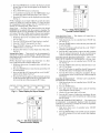
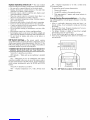
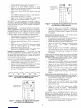
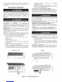
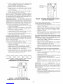
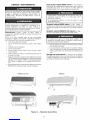
Unit Operation(Fig.13)-- In the event that the remote
control is not working or has been misplaced, the unit wilt
operate as follows:
40BN018,024,030 Units always operate by the remote
control. If you lose or break the remote, the unit wilt continue
to operate but settings cannot be changed until you get a new
relnote control.
To Turn Unit Off Push the Operation Push Button located
under the fiont cover. See Item I, Fig. 13. The AISI'O/OFF
indicator light wilt go off
To Turn Unit On Push the Auto/Off button located under
the tiont cover. See Item I, Fig. 13. The AUTO/OFF indicator
light will light. The unit will operate at the settings that have
been promalrnned using the remote control.
40BN036 Unit will operate according to predetermined
factory settings.
To Turn Unit Off Slide the Operation Switch on the unit
(Item I, Fig. 13) to the OFF position.
To Turn Unit On Slide the Operation Switch on the unit
(Item I, Fig. 13) to the AUTO position. The unit wilt operate at
a temperature setting of 74 F and will autolnaticalty select the
required operation mode and tan speed to maintain this setting.
40BN018,024,030 40BN036
QFILTER RESET
G
E
C
D
A
B
AUTO
OFF
REMOTE O, (9 © U,
FEATURE DESCRIPTION
AInfrared Receiver Receives transmissions from the remote controller.
B FILTER Indicator Light Lights when the air filters require cleaning.
C (ON)/(AIR COND Indicator Light Lights when the air conditioner operates. Flashes when defrosting.
DTIMER Indicator Light Lights when a TIMER Start or Stop time is set.
E POWER Indicator Light Lights when the air conditioner is connected to the electricity supply of the proper
line voltage.
G SERVICE Indicator Light Lights or flashes accordingly to the malfunction. (See further information on
page 11).
Operation Push Button Turns the air conditioner ON (Auto) Mode and OFF without Remote Control.
40BN018,024,030) _Resets unit after malfunctions and resets the Filter indicator light. (Press the but-
ton continuously for 5 seconds.)
I Operation Slide Switch Turns the air conditioner ON (Auto) Mode and OFF without Remote Control.
(40BN036) _Resets unit after malfunctions and resets the Filter indicator light. (Slide Operation
Switch to OFF position for 5 seconds and then return the switch to remote.)
• Operates the air conditioner using the remote controller when the operation switch
is in REMOTE position.
Fig. 13 -- Indoor Unit Display Panel Features

CLEANING AND MAINTENANCE
To avoid the possibility of electric shock, always turn off
power to the system betbre performing any cleaning or
maintenance to the system. Turn offthe outdoor disconnect
switch located near outdoor unit. Be sure to disconnect
indoor unit if on a separate switch.
Operating the system with dirty air filters may damage the
indoor unit and could cause reduced cooling performance.
Intermittent system operation, fiost build-up on indoor coil
and blown fiJses may also result fiom system operation
with dirty air filters.
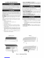
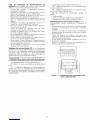
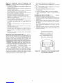
Air Filters -- Relnove and clean the air filters when the
Filter indicator light on the unit display panel is lit. See Fig. 13
and 14.
NOTE: If air filters show sills of excessive wear or are tom,
they must be replaced. Contact your local dealer for replace-
ment filters.
1. Open front panel on unit.
2. Pull filters down to relnove. (See Fig. 14.)
3. Vacuum filters.
4. Clean with warm water.
5. Shake filter to remove excess water and dry thorou_lly.
6. Replace filter by sliding filter behind fiont m-ilteuntil fit-
ter snaps in place.
7. Slide Operation Switch on unit to OFF position to reset
Filter stares indicator light on 40BN036 units, or press the
ON/OFF button for 5 seconds on 40BN018,024 and 036
units.
8. Slide Operation Switch on unit to REMOTE 3osition to
resume relnote control operation.
Indoor Unit (40BN) Front Panel-- To clean the
brontpanel on the indoor unit, wipe the outside with a soft, dry
cloth. If necessary, a mild liquid detergent can be applied and
wiped offwith a dry cloth.
When cleaning the fiont panel, do not use water hotter than
105 F and do not pour water onto the tan coil.
Do not use abrasive or petroleum based cleaners as they
may damage the fiont panel.
Indoor Unit (40BN) Coil -- To clean the indoor unit
coil, remove the fiont panel and vacuum the coil fins. Avoid
bending or damaging the fins.
Outdoor Unit (38BN018-036) Coil -- To clean the
outdoor unit coil follow the steps below:
Sharp fins and other metal parts on the outdoor unit coil
can cause personal injury during cleaning.
1. Remove aW dirt, debris or obstruction from discharge
opening.
2. Use a garden hose to spray water on coil. Be sure to spray
between coil fins to relnove any debris that may inhibit
heat transfer.
Condensate Drains- Clean all condensate drains at
the start of each cooling season. Check the flow by pouring wa-
ter into the drain.
40BN018,024,030 40BN036
Fig. 14 -- Removing Air Filters

SystemOperation Check List -- The items outlined
in the tbllowing list will help to assure proper system operation:
• Be sure unit is connected directly to electrical supply.
• Replace both remote control batteries at the same time
when the Low Battery symbol appears.
• Point the remote control toward the unit display panel
when transmitting a command.
• Place the remote control in a location where there is a
direct line for transmission of data to the unit.
• Select a moderate temperature setting. Extreme tempera-
tures waste electricity.
• Keep doors and windows closed while unit is operating.
• Close air vents in unoccupied rooms to save electricity.
• Contact an authorized service representative ifa problem
arises that cannot be easily resolved.
• Do not perform cleaning or maintenance activities while
unit is on.
• Keep remote control out of direct sunlight and heat.
• Keep display panel on unit away fiom direct sunlight and
heat as this may interfere with relnote control transmissions.
• Do not block air intakes and outlets on the indoor or
outdoor units.
DIP Switch Settings- The relnote control contains
seven DIP switches, located in the battery compartment, two of
which control special system characteristics. See Fig. 15. The
DIP switch default positions are set according to the model air
coMitioner installed, as per the following table.
SWITCH I 1 2 3 4 5 6 7
POSITION I ON OFF OFF OFF OFF ON OFF
Switch No. 3 should be set as follows:
OFF (default) When only one air conditioner is installed
in the room.
ON When there are tvxs_air conditioners with relnote
controllers installed in the room, in one of the relnote control-
lers this switch must be in the ON position. To activate the new
switch setting, simultaneously press the MODE and ROOM
buttons.
Switch No. 4should be set as follows:
OFF Displays temperature in °C, with a 24-hour clock
format.
ON Displays temperature in °E with a 12-hour clock
(PM indictor) tbnnat.
To operate the special systems characteristics:
1. Relnove the batteries.
2. Set the DIP switches to the required positions.
3. Wait approximately 2 minutes and return batteries to
proper position.
Energy Saving Recommendations -- The follow-
ing recolrnnendations will add greater efficiency to the duct
l?ee system:
• Select a comfortable thermostat setting and leave it at
chosen setting. Avoid continually raising and lowering
the setting.
• Keep unit filter clean. Frequent cleaning may be neces-
sary depending on indoor air quality.
• Use drapes, curtains or shades to keep direct sunlight
froln heating room on very hot days.
• Do not obstruct front grille air intake on front panel.
• Turn on air conditioning before indoor air becomes too
uncomfortable.
ON
OFF
/
1234567
Fig. 15 -- DIP Switch Location in Remote Control

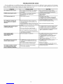
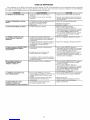
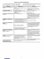
TROUBLESHOOTING GUIDE
Your air conditioner is very reliable and requires little maintenance. However, the air conditioner's proper operation can be interrupt-
ed by a malfunction in the electrical system oi by incorrect operation. Youcml try to overcome these simple malfunctions yourselt; with
the aid of the t;_llowing table and the malfanction displays shown in Fig. 16.
PROBLEM POSSIBLE CAUSE SOLUTION
Air conditioner does not work. • No command is transmitted to air conditioner. • Press the On/Off (Transmission) button.
• Air conditioner did not receive transmitted • Make sure that remote controller is pointed at air
command, conditioner during command transmission.
POWER indicator light is not lit. • Air conditioner is not properly connected. • Check electrical connection.
• Automatic interrupter switched Off. • Reset interrupter.
• Fuse burned. • Replace fuse.
FILTER indicator light is lit. • Filters require cleaning. • Remove and clean filters.
• For 40BN038 move operation switch to OFF
position for 5 sec. and return it to REMOTE.
• For 40BN018,024,030 press the operation push
button continuously for 5 seconds.
Air conditioner is working, but • Desired temperature setting is higher than • Lower the desired temperature setting.
does not perform the required room air temperature when operating in the
operation. COOLING mode.
• Desired temperature setting is lower than room • Raise the desired temperature setting.
air temperature when operating in the HEATING
mode.
(ON)/(AIR COND). Indicator light is • The control system is malfunctioning.
continuously flashing.
Various indicator lights
behave differently than
shown in Fig, 13,
• There is no direct line of sight between
the remote controller and the air conditioner.
• The air conditioner has reached the desired
temperature and stopped the compressor oper-
ation (thermostat function).
• Incorrect operation or malfunction.
• For 40BN036 slide the operation switch to OFF
position for 5 sec. and return it to REMOTE.
• For 40BN018,024,030 press the operation push
button, continuously for 5 seconds. Press once
again to operate the air conditioner.
Air conditioner does not operate • In 40BN036 the operation push button is in
with the remote controller. AUTO or OFR (For 40BN018,024,030 go to
next bullet.)
• The remote controller batteries are weak. • Replace the batteries.
• The remote controller is malfunctioning. • Turn the air conditioner On and OFF using the
operation push button or slide switch.
The remote controller of another • Both remote controllers are transmitting • Call service personnel.
air conditioner interferes with on the same wavelength.
your air conditioner's operation.
• For 40BN018,024,030 press the operation push
button continuously for 5 seconds.
• For 40BN036 slide the operation slide switch
to OFF position for 5 sec. and return it to
REMOTE.
• Restart the air conditioner, if the problem per-
sists, call service personnel.
• For 40BN036 turn the operating switch to
REMOTE position.
10

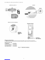
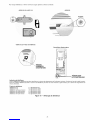
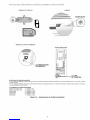
On each Malfunction, Indicator Light (red) will flash at a constant rate:
40BN018,024 AND 030 40BN036
POWER
40BN018,024 AND 03040BN036
Electronic Control
SERVICE
INDICATOR
LIGHT
LIGHT ON
/THE CONTROL
Malfunction Indication Display
For 40BN036 the malfunction can be read by the rate of the flashing light on the control. (Raise the front grille list.)
For 40BN018,024,030 the malfunction can be read without raising the front grille by the rate of the flashing service light.
Malfunction Display Light
TH1 Malfunction • 1 short flash
TH2 Malfunction • 2 short flashes
Low Pressure Malfunction • 3 short flashes
High Pressure Malfunction ° 4 short flashes
Low Voltage Malfunction • 5 short flashes
High Voltage Malfunction • 6 short flashes
Fig. 16 -- Malfunction Displays
]!

To save time on a selw'ice call, fill out the information listed below:
Dealer's Name
Address
Telephone
Indoor Model #
Indoor Serial #
Purchase
Outdoor Model #
Outdoor Serial #
Copyright 2003 Carrier Corporation
Manufacturer reserves the right to discontinue, or change at any time, specifications or designs without notice and without incurring obligations.
PC 111 Catalog No. 533-80098 Printed in U.S.A. Form OM38/40-4 Pg 12 4-03 Replaces: New

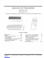
MANUEL D'UTILISATION
38BNB,BNE018-036
40BNB,BNE018-036
Syst+mes de climatisation et pompe h chaleur sans conduites pour installation murale
TABLE DES MATII£RES
Page
INTRODUCTION ............................. 14
GI_NI_RAL .................................. 14,15
MODES DE FONCTIONNEMENT ............. 14
Tt_LECOMMANDE .......................... 14
FONCTIONNEMENT ....................... 15-18
FONCTIONNEMENT DE LA Tt_Lt_COMMANDE. 15
FONCTIONNEMENT DE L'APPAREIL ......... 18
NETTOYAGE ET ENTRETIEN ............... 20,21
FILTRES A AIR ............................. 20
Page
FACE AVANT DE L'UNITt_ INTt_RIEURE ....... 20
SERPENTIN DE L'UNITt_ INTt_RIEURE ........ 20
SERPENTIN DE L'UNITE EXTt_RIEURE ....... 20
DRAINS DE CONDENSATION ................. 8
LISTE DE VITRIFICATION
DE FONCTIONNEMENT DU SYST]_ME ..... 21
Rt_GLAOES DES COMMUTATEURS DIP ........ 21
RECQMMANDATIONS D't_CONOMIE
D'ENERGIE ............................. 21
GUIDE DE DI_PANNAGE .................... 22-24
Le fabricant se reserve le droit d'interrompre ou de changer atout moment les specifications ou la conception sans preavis et sans engagement de sa part.
Livre 1 14 PC 111 Catalogue No. 533-80098 Imprim6 aux E,-U. Formulaire OM38/40-4 Pg 13 4-03 Remplace: Nouveau
Onglet 3e 12f

INTRODUCTION
Merci d'avoir optd pour un systbme sans conduites
StreamlineL_. Cet appareil a _td construit avec le m_me soin et les
m_mes techniques de conception utilis_es pour les &luipements de
climatisation de l'Astrodome au Texas, la Chapelle Sixtine il
Rome, la Chambre des deputds des Etats-Unis et des milliers
d'autres installations de par le monde.
Les syst_mes sans conduites procurent un confort maximum
avec un minimum de nuisances sonores. En plus de la fonction de
climatisation et/ou de chauffage, ce systbme sans conduites filtre et
deshumidifie l'air de la pibce pour foumir un conibrt maximum.
IMPORTANT: Les systbmes sans conduites doivem _tre
install& par du personnel quatifid et autorisd uniquement
et au moyen de mat&iaux et accessoires approuvds. En
cas de besoin d'assistmlce technique, d'entretien ou de
r@aration, contacter l'instatlateur ou appeler le 1-800-
227-7437.
GI_NI_RAL
Ce systbme sans conduites petit _tre r_gl_ et mis en
fonctionnement g partir de la tdl_commande (foumie). Voir Fi_lre
1. Si la tdl_commande est _gar_e, le syst+me petit fonctionner il
partir du mode <_Auto >>de l'appareil.
Modes de fonctionnement -- Ce systbme possbde 5
modes de fonctionnement :
Climatisation (COOLING)
Ventilation uniquement (FAN ONLY)
Chaufl:age (HEATING) (si disponible)
D_shumidification (DRY)
Auto (AUTO)
CLIMATISATION En mode de Climatisation, le systOme
refroidit, assbche et filtre l'air de la pibce.
VENTILATION UNIQUEMENT En mode de ventilation
seule, le systbme filtre et fait circuler Fair de la pibce sans changer
la temperature de Fair.
CHAUFFAGE En mode chauffage, le syst_me chauffe et filtre
Fair de la pi6ce.
Dt_SHUMIDIFICATION En mode deshumidification, le
syst_me assbche, filtre et refroidit l_g&ement Fair de la pi6ce. Ce
mode de fonctionnement ne remplacepas b_un deshumidificateur.
AUTO En mode Auto, le systbme dimatise ou chauffe
automatkluement Fair de la pibce en fonction d'un r_glage de
temp&amre (valeur pr_definie).
Si la temperature de la pibce est inf&ieure /_ la x_aleur
pr_definie, le systbme fonctionnera en mode chaufl:age. Si la
temperature de la pi6ce est sup&ieure /_la valeur pr_definie, le
systbme fonctionnera en mode climatisation.
Teleeommande -- La tdl_commande transmet les
commandes de r_glage et de fonctionnement au systbme. La
tdl_commande possbde un @ran d'affichage qui indique les
parambtres actuels de foncfionnement du systbme. La
t_l_commande petit _tre fix_e stir une surface/_ l'aide du support de
montage foumi. Voir Fi_lre 1.
Manipuler la tdl_commande avec soin et &'iter de la mouiller.
Cecipourrait l'endommager.
Ne pas laisser la tdl_commande dans un tiroir ou gproximitd
d'un appareil d_gageant de la chaleur, car le syst_me essaiera
derefroidir l'air quienvironne la tdl_commande.
IMPORTANT: La tdl_commande et l'appareil _changent
en permanence des info_rnationsrelatives g la temp&amre
de la pi@e. Lots du fonctionnement de la tdldcommande/_
partir du support mural, s'assurer que la t_l_commande et
l'appareil sont en regard direct. La tdl_commande petit
piloter l'appareil _ une distance de jusqu'g 23 pieds
( 7m6tres) si aucun obstacle n'est pr&ent.
"NAUT COOUNG,O,!'o,SWEEP
BOUTON / _ HEATING FUNCTION
HAJT/BAS _ ,_'}: DRY _HIGH
4, @ UTO @*NTO
BOUTONS DE LA TELECOMMANDE --
OPTIONS DE PROGRAMMATION
Figure 1 -- Systbme sans conduites
TELECOMMANDE
SUPPORT DE MONTAGE
14

La tdl_commande peut declencher les fonctions suivantes :
• Mise en marche et arr_t du systbme
• S_lection du mode de fonctionnement
• R_glage de la temperature de la piece et de la vitesse de
ventilation
• D_finition de p_riodes de temps pour le fonctionnement
automatique
INSTALLATION DES PILES Deux piles alcalines AAA de
1,5 volt (foumies) sont n_cessaires pour le fonctionnement de la
t_l_commande. Voir la Fi_lre 2 pour l'emplacement des piles.
Pour installer les piles :
1. Enlever le couvercle du compartiment des piles en le faisant
coulisser.
2. Insdrer les piles en s'assurant de respecter la polaritd
indiqu_e il l'int_rieur du compartiment.
3. Replacer le couvercle du compartiment des piles.
REMARQUE: Remplacer les piles lorsque l'indicateur <<Low
battery >>(batterie thible) apparait sur l'_cran de la tdldcommande.
t_CRAN D'AFFICHAGE I1 existe cinq indicateurs de mode
de fonctionnement qui apparaissent sur l'_cran de la
tdldcommande. Voir Fi_lre 3.
FONCTIONNEMENT
Fonctionnement de la telecommande -- La
tdldcommande poss8de 3 boutons (voir Figure 4) qui sont utilis_s
pour le fonctionnement et le contr61e du syst_me :
• Bouton MODE change le mode de fonctionnement
• Bouton UP/DOWN (haut/bas) s_lectionne le mode de
fonctionnement desir_
• Bouton ON/OFF (marche/arr&) met en marche ou arrSte
le syst8me et transmet les sdlections de programmation
l'appareil.
--
k _ _ ..... _ ../
ARRIERE DE
LA TELECOMMANDE
2 PILES AAA 1,5 V
Figure 2 -- Emplacement des piles de la
tel_commande
CLIMATISATION
COUVERCLE DU
COMPARTIMENT DES PILES
CHAUFFAGE
VENTILATION DESHUMIDIFICATION
UNIQUEMENT %
AUTO
Figure 3 -- Indicateurs du mode de fonctionnement
sur la tel_commande
REMARQUE : Lors de la transmission d'une colTnnande il partir
de la t4l_commande vers l'appareil, s'assurer de pointer la
t414commande en direction du c6t4 droit de l'appareil. Voir Fi_lre
4. L'appareil confirmera la r4ception de la commande en _mettant
deux bips audibles.
IMPORTANT: Si aucun changement n'intervient pendant
10 secondes, la tdl_commande retoumera au r_glage precedent.
VITESSE DE VENTILATION Suivre les _tapes ci-dessous
pour s_lectionner le mode et la vitesse de ventilation :
1. Appuyer sur le bouton MODE pour s_lectionner le mode
Fan (ventilation).
2. Appuyer sur les flbches UP/DOWN (haut/bas) pour
s_lectionner la vitesse de ventilation appropri_e ou le mode
Auto.
3. Appuyer sur le bouton ON/OFF (marche/an'at) pour envoyer
les changements vers l'appareil.
Rt_MARQUE : Si l'appareil fonctionne en mode de
DESHUMIDIFICATION, la ventilation ne lbnctionnera qu'g
basse vitesse et la vitesse ne peut _tre chang_e.
Rt_GLAGES DE TEMPt_RATURE Les r_glages de
temperature peuvent _tre facilement modifies en pointant la
tdl_commande vers l'appareil et en appuyant sur le bouton UP/
DOWN (haut/bas) jusqu'i_ ce que la temperature d_sir_e apparaisse
sur r_cran. Le symbole '_" apparait/_ chaque fois que l'on appuie
sur le bouton UP/DOWN (haut/bas).
I1 est _galement possible de changer la temperature comme
suit :
1. S_lectionner l'affichage de temperature en appuyant sur le
bouton MODE. Le symbole de de_s sim_ _ c6td des
chiffres semet g clignoter.
2. Appuyer sur le bouton UP/DOWN (haut/bas) pour
s_lectionner la temperature desir_e. L'_tendue de
temperature disponible est de 54 F/_ 90 F.
3. Appuyer sur le bouton ON/OFF (marche/arr_t) pour envoyer
les changements vers rappareil.
DIRECTION DE L'AIR Effecmer les _tapes suivantes pour
modifier la direction de Fair sortant de l'appareil :
1. Appuyer sur le boumn MODE pour s_lectionner la fonction
Sweep (balayage).
2. Appuyer sur le haut du bouton UP/DOWN (haut/bas) pour
deplacer le d4flecteur d'air de l'appm'eil de haut en bas. Le
symbole de circulation d'air indique un deplacement.
3. Appuyer sur le has du bouton UP/DOWN (haut/bas). Le
d4flecteur s'arr4te sur l'angle acmel. Le symbole de
circulation d'air reste en position fixe.
4. Appuyer sur le bouton ON/OFF (marche/arr4t) pour envoyer
les changements vers l'appareil.
REMARQUE : Si l'on choisit de placer le deflecteur d'air dans
une position fixe, le d4flecteur s'arr4te _ rangle dans lequel il se
trouvait lors de la pression sur le bouton ON/OFF (marche/an'4t).
Rt_GLAGE DE L'HORLOGE
1. Faire coulisser le couvercle frontal de la t414commande sous
le bouton ON/OFF (marche/arr4t). Voir Figure 4.
2. Appuyer sur le bouton CLOCK (horloge) _ l'aide de la
pointe d'un stylo ou d'un trombone. Voir Figure 5.
3. Appuyer sur le bouton UP/DOWN (haut/bas) pour r4gler les
minutes.
4. Appuyer sur le bouton MODE. Les chiffres des heures
clignotent.
5. Appuyer sur le boumn UP/DOWN (haut/bas) pour r_gler les
heures.
6. Pour confirmer le r_glage acmel de l'horloge, appuyer de
nouveau sur le bouton CLOCK (horloge) g l'aide de la
pointe d'un stylo ou d'un trombone. La t414commande
retoumera automatiquement g l'_cran pr4c_dent et affichera
l'horloge.
15

OUVERTURE DE TRANSMISSION DE SIGNAL INFRAROUGE
\
HORLOGE_-_-_-
INDICATEURS DE DEBUT/FIN
DE MINUTERIE JOURNALIERE
BOUTON DE MODE
INDICATEURS DE MODE
DE FONCTIONNEMENT -
CLIMATISATION, VENTILATION,
CHAUFFAGE, DESHUMIDIFICATION,
AUTO
INDICATEURS DE VENTILATION
FAIBLE, MOYEN, FORT, AUTO
DE TEMPERATURE
DE TRANSMISSION
BAS INDICATEUR DE BATTERIE
DESIREE
INDICATEUR D'ACTIVITE DE CAPTEUR
INDICATEUR DE BALAYAGE
BOUTONS DE REGLAGE
DE MINUTERIE*
PANNEAU COULISSANT
" (HORLOGE)*
DE LA PIECE*
(DELAI)
*Boutons situes sous le couvercle & coulisse superieur.
Figure 4 -- T_l_commande
PROGRAMMATION DES Pt_RIODES DE TEMPS Le
systbme sans conduites peut atre pro_amm_ pour fonctionner/_
des niveaux desiras. S'assurer de r_gler l'hofloge avant de
pro_ammer le syst_ne.
Les increments de temps sont des intervalles de 10 minutes.
Le tdmoin indicateur de marche/arrat d'horloge de
l'appareJl s'allume lorsqu'une de p_riode de temps est
pro_amm_e. Voir Figure 4.
L'_cran de la t_l_commande affJche l'heure de Marche/
Arrat de la p_rJode de temps qui est la plus proche de
l'heure actuelle. SJ l'appareil est sur ON (marche),
<_STOP _>(arr_t) et la pdrJode de temps sont affich_s. Si
l'appareil est sur OFF (an'at), <_START >>(marche) et la
p_riode de temps sont affich_s.
IMPORTANT : Veiller _ bien pointer la tdl_commande en ]
direction de l'unJtd lorsque l'on appuie sur les boutons I
TIMER (minuterie) ou SET (raglage).
Rdgtage de l'heure de Marche/Arrat La fonction de
minuterJe est utilis_e pour d_finir les heures de marche/an'at Trois
p_riodes de temps diff_rentes pouvant atre s@araes d'un
maximum de dix heures et sim_es dans une tranche de 24 heures
peuvent atre pro_ammdes il l'aJde de cette fonction. Figure 5 -- Emplacement du bouton de r_glage
de I'horloge sur la tel_commande
16

1. Faire coulisser le couvercle frontal de la tdl_commande sous
le bouton ON/OFF (marche/arr&). Voir Fi_lre 4.
2. Appuyer sur le bouton TIMER (minuterie).)t chaque
pression sur le bouton, rheure de marche ou d'alT& suivante
s'afiSche sur l'_cran. Voir Fi_lres 6 et 7.
3. Appuyer sur le bouton UP/DOWN (haut/bas) pour ragler
l'heure.
4. Pour definir une autre p_fiode de temps, appuyer sur le
bouton TIMER (minuterie) pour aller _ une autre p&iode de
temps et r@&er les _tapes 2 et 3 ci-dessus.
5. Appuyer sur le bouton SET (r_glage) pour valider rheure
affich_e une fois rop&ation termin_e. Voir Finite 4.
REMARQUE:Si aucun changement n'intervient pendant 10
secondes, la tdl_commande retournera _ l'affichage precedent.
Pour corriger une erreur, les rdglages de minutefie pro_ammds
doivent &re annulus et r&entras. Voir le parauaphe Annulafion de
la minutefie de jour.
Minuterie de nuit La fonction de minutefie de nuit permet de
definir la temp&'amre desirae durant la p&iode de sommeil de
l'occupant de la pibce. La temp&amre de Fair de la pibce atLmnente
_aduellement jusqu'_ ce que la p_fiode de temps soit termin_e.
L'appareil retoume ensuite au raglage de temp&amre prac_dent.
Effectuer les _tapes suivantes pour d_finir la minuterie de nuit :
1. Faire coulisser le couvercle frontal de la tdl_commande sous
le bouton ON/OFF (marche/arr_t). Voir Figure 4.
2. Appuyer sur le bouton TINIER (minuterie) jusqu'il ce que la
fonction Sleep (sommeil) apparaisse.
3. S_lectionner la p_riode de temps <_SLEEP >>(sommeil). Voir
Figure 8.
4. Appuyer sur le bouton UP/DOWN (haut/bas) pour definir
l'heure de debut et appuyer sur le bouton TIMER
(minutefie) pour definir l'heure de fin.
5. Appuyer sur le bouton SET (r4glage) pour valider rheure
affich_e une fois l'op_rafion termin_e. Voir Fi_lre 4.
Rd_ta_e de la minuterie de iour Les p_riodes de temps
peuvent _tre pro_ammdes pour ihire fonctionner le systbme il des
moments donn_s durant une p_riode de 24 heures. Cette fonction
de minuterie peut _tre utilis_e pour les 3 p_riodes de temps et la
p_riode de sommeil decrite ci-dessus.
REMARQUE : La minuterie de jour ne lbnctionne que lorsqu'il
existe un vis-it-vis direct entre la t_ldcommande et l'appareil.
1. Faire coulisser le couvercle frontal de la tdl_commande sous
le bouton ON/OFF (marche/arr_t). Voir Figure 4.
2. Appuyer sur le bouton TIMER (minuterie) pour s_lecfionner
la p_fiode de temps qui sera activ_e journellement.
3. Appuyer sur le bouton SET (r_glage) et le maintenir enfonc_
jusqu!a ce que le mot <_DAILY >>(ioumellement) apparaisse
sur l'_cran. Voir Figure 9.
Figure 6 -- Affichage du r6glage de la minuterie
sur 1'6cran de la tel6commande
DE MINUTERIE ,D,_,s _EE_
MOO_ FAN SWEE_
&
Figure 7 -- Indicateur de reglage de la minuterie
sur 1'6cran de la tel_commande
INDICATEUR
DE MINUTERIE
DE NUIT -_-_-
Figure 8 -- Indicateur de minuterie de mise en veille
sur 1'6cran de la tel_commande
4. Appuyer de nouveau sur le bouton SET (r_glage) pour
confirmer le fonctionnement joumalier de la p_fiode de
temps s_lecfionn_e. S'assurer de pointer la tdl_commande
en direction de l'appareil lorsque l'on appuie sur le bouton
SET (r_glage).
Annulation de la minuterie de iour Cette foncfion annulera
le pro_amme de minutefie de jour s_lectionn&
1. Faire coulisser le couvercle frontal de la tdl_commande sous
le bouton ON/OFF (marche/arr_t). Voir Figure 4.
2. Appuyer sur le bouton TIMER (minutefie) pour s_lectionner
la p_riode de temps qui sera activ_e joumellement.
3. Appuyer sur le bouton SET (rdglage) et le maintenir enfonc_
jusqu'a ce que le mot <_DAILY>> (ioumellement)
disparaisse de l'_cran.
4. Appuyer de nouveau sur le bouton SET (r_glage) pour
d_sactiver le fonctionnement journalier de la p_riode de
temps s_lectionn_e. S'assurer de pointer la tdl_commande
en direction de l'appareil lorsque l'on appuie sur le bouton
SET (r_glage).
Annulation d'une heure de ddbut ou de fin d'une pdriode de
temps spdcifique I1 est possible d'annuler une ou plusieurs
minuteries en effectuant les dtapes suivantes :1.Faire coulisser
le couvercle frontal de la tdl_commande sous le bouton ON/
OFF (marche/arr&). Voir Figure 4.
2. Appuyer sur le bouton TIMER (minuterie) et s_lectionner la
minuterie que l'on veut annuler (1,2,3, ou Sleep (sommeil))
3. Appuyer sur le bouton CLEAR (efl:acer) pour annuler la
p_riode de temps s_lectionn_e. Les heures de debut et de fin
disparaitront de l'_cran.
4. Appuyer sur le bouton SET (r_glage) pour confinner
l'annulation. S'assurer de pointer la t_l_commande en
direction de l'appareil lorsque l'on appuie sur le bouton SET
(r_glage).
Annulation de toutes les pdriodes de temps I1 est possible
d'annuler routes les minuteries en effecmant les _tapes suivantes:
1. Faire coulisser le couvercle frontal de la t414commande sous
le bouton ON/OFF (marche/arr_t). Voir Figure 4.
2. Appuyer sur le bouton TIMER (minuterie).
3. Appuyer sur le bouton CLEAR (efl:acer) et le maintenir
enfonc4 jusqu'il ce que toutes les heures de debut et de fin
disparaissent de l'4cran.
4. S'assurer que le t4moin de minuterie est 4teint sur l'appareil.
5. Appuyer sur le bouton SET (r4glage) pour confirmer
l'annulation. S'assurer de pointer la t414commande en
direction de l'appareil lorsque l'on appuie sur le bouton SET
(r4glage).
AFFICHAGE DE LA TEMPt_RATURE DE L'AIR DE LA
PII_CE La temperature acmelle de Fair de la piece est
automatiquement affich_e lorsque la t_l_commande est mise hors
tension. Pour afficher la temp4ramre de l'air de la pi4ce lorsque
l'appareil est mis sous tension :
1. Faire coulisser le couvercle frontal de la t414commande sous
le bouton ON/OFF (marche/arr_t). Voir Figure 4.
17

INDICATEUR
DE MINUTERIE .... "
DE JOUR ++o+..... j72o
I 2_.DAILY
MOOE FAN SWEEP
+%
O
Figure 9 -- Indicateur de minuterie de jour
sur 1'6cran de la tel_commande
i++ o
Figure 10 -- Indicateur de temp+rature de la pi+ce
sur l'+cran de la t61+commande
2. Appuyer sur le bouton ROOM (pibce). La temp&ature
acmelle de l'air de la piece sera affich_e pendant plusieurs
secondes puis disparaitra. Voir Fi_lre 10.
Dt_CALAGE Dt_BUT/FIN Cette fonction d_cale la fonction
d_but/fin par incr&nents de 1 heure. Le ddcalage de d_but/fin peut
_tre pro_ammd avec l'appareil en position ON (marche) ou OFF
(arr_t).
Avec l'appareil en position ON (marche) :
1. Faire coulisser le couvercle frontal de la tdl_commande sous
le bouton ON/OFF (marche/arr_t). Voir Fi_lre 4.
2. Appuyer sur le bouton DELAY (d_calage). L'hofloge
avancera d'une heure et le mot <_STOP >>(arr_t) et le chJfl?e
3 clignoteront. Voir Figure 11.
3. Appuyer sur le bouton DELAY (d_calage) une fois pour
fiaire avancer l'horloge d'une heure suppl&nentaire jusquti_
ce que le d_calage d_sir_ soit atteint. S'assurer de pointer la
tdl_commande en direction de l'appareil lorsque l'on appuie
sur le bouton DELAY (d_calage).
4. Le mot <_STOP >>(arr_t) cessera de clignoter une fois que la
commande aura _td transmise et revue par l'appareil.
Avec l'appareil en position OFF (arr_t) :
1. Faire coulisser le couvercle frontal de la tdl_commande sous
le bouton ON/OFF (marche/arr_t). Voir Fi_lre 4.
2. Appuyer sur le bouton DELAY (d_calage). L'horloge
avancera d'une heure et le mot <_START >>(marche) et le
chifl?e 3 clignoteront. Voir Fi_lre 11.
3. Appuyer sur le bouton DELAY (d_calage) une fois pour
fiaire avancer l'horloge d'une heure suppl_mentaire jusqu!il
ce que le d_calage d_sir_ soit atteint. S'assurer de pointer la
tdl_commande en direction de l'appareil lorsque l'on appuie
sur le bouton DELAY (d_calage).
4. Le mot <_START >>(marche) cessera de clignoter une fois
que la commande aura _td transmise et revue par l'appareJl.
Annulation de ddbut/fin ddcald Pour annuler la fonction de
ddcalage de d_but/fin, suivre les instructions du paragraphe
AnnulatJon d'une heure de d_but ou de fin d'une p&iode de temps
sp_cifique.
REMARQUE : Le r_glage de d_lai est enregistr_ dans la p_fiode
de temps 3.
FONCTION DE Dt_TECTION LOCALE (tdl_commande
bidirectionnelle) La fonction de d_tection locale permet _ la
t_l_commande de fonctionner en transmettant la temperature de
l'air de la piece/_ l'appareil/_ des intervalles r_diers,/_ partir de
l'endroit off la t_l_commande se trouve dans la pibce. L'appareil
fonctionnera de mani_re _ ce que l'air sim_ _ proximitd de la
tdl_commande atteigne la temperature d_sir_e.
Pour rd_ler la fimction de ddtection locale :
1. Fake coulisser le couvercle frontal de la tdl&ommande sous
le bouton ON/OFF (marche/arr_t). Voir Figure 4.
2. Appuyer sur le bouton SENSE (d_tection). L'Jc6ne
<_House >>(maison) apparait sur l'&ran. Voir Figure 12.
3. Placer la tdl_commande _ l'emplacement d_sir_ dans la
pibce. S'assurer qu'il exJste un vis&-vis direct entre la
tdl_commande et l'appareJl.
Pour annuter la fonction de ddtection locale : Lorsque la
tdl_commande est dans la fonction <_Local Sense >>(d_tection
locale), appuyer sur le bouton SENSE (d_tection). Le symbole
++o++ @ I o
DALLY
ECRAN DE PROGRAMMATION AVEC APPAREIL
EN MARCHE
+++++i++2o
3 DALLY
ECRAN DE PROGRAMMATION AVEC APPAREIL
,/_I'ARRC:T
Figure 11 -- Indicateurs de d6calage de d6but/fin sur
1'6cran de la tel_commande
If:%
o
I'gg+
& &
INDICATEUR
- -- DE DETECTION
LOCALE
Figure 12 -- Indicateur d6tection locale sur 1'6cran de
la tel6commande
18

<<House >>(maison) disparait de l'_cran et la fonction de ddtection
locale est annul_e.
Fonction de I'appareil (Figure 13) -- Dans le cas og la
tdl_commande ne fonctionne pas ou qu'elle a _td _gar_e, l'appareil
fonctionne de la mani_re suivante :
40BN018,024,030 Appareil toujours contr61_ par la
t_l_commande. Si vous perdez ou endommagez la tdl_commande,
l'appareil continuera de fonctionner mais il sera impossible de
changer les r_glages jusqu'g ce que vous obteniez une
tdl_commande neuve.
Pour arr_ter l'appareil Appuyer sur le bouton poussoir sim_
sous le couvercle frontal. Voir _l_ment I, Fi_lre 13. Le tdmoin
lumineux AUTO/OFF (auto/arr_t) s'_teindra.
40BN018,024,030
Pour allumer l'appareit Appuyer sur le bouton Auto/Off
(auto/arr_t) sims sous le couvercle frontal. Voir _l_ment I, Fignre
13. Le tdmoin lumineux AUTO/OFF (auto/arr_t) s'allumera.
L'appareil fonctionnera en fonction des r_glages qui ont _td
pro_ammds g l'aide de la t_l_commande.
40BN036 L'appareil fonctionnera en fonction des r_glages
d'usine.
Pour arr_ter l'appareil Placer le commutateur de
fonctionnement de l'appareil (_l_ment I, Fi_lre 13) sur la position
OFF (arr_t).
Pour allumer l'appareit Placer le commutateur de
fonctionnement de l'appareil (_l_ment I, Fi_lre 13) sur la position
AUTO. L'appareil fonctionnera il un r_glage de temp_ratnre de
40BN036
OFILTER RESET
G
/
/
/"
i//
E
C
D
A
B
AUTO
OFF
REMOTE
"A, "'"° B C D E
O, C_ © U.
FONCTION DESCRIPTION
AR6cepteur infrarouge Recoit les transmissions de la t61ecommande.
B Temoin lumineux FILTER (filtre) S'allume Iorsque le filtre &air doit _tre nettoy&
C Temoin lumineux (ON)/(AIR COND) S'allume Iorsque le climatiseur fonctionne. Clignote lots du d_givrage.
marche/climatisation)
D Temoin lumineux TIMER (minuterie) S'allume Iorsque I'heure de d6but ou de fin de minuterie est d6fini.
E Indicateur lumineux d'alimentation S'allume Iorsque le climatiseur est branche sur une prise _lectrique du voltage appropri&
G Temoin lumineux SERVICE S'allume ou clignote en fonction du probl_me. (Voir informations complementaires & la
(entretien) page 23)
Bouton poussoir de mise en marche • Mise en marche (mode auto) et arr_t du climatiseur sans tel_commande.
40BN018,024,030) •Reinitialise I'appareil apres un probl_me de fonctionnement et r_initialise le t_moin de
filtre. (Appuyer sur le bouton pendant 5 secondes).
Commutateur de fonctionnement • Mise en marche (mode auto) et arr_t du climatiseur sans tel6commande.
I (40BN036) • Reinitialise I'appareil apres un probl_me de fonctionnement et r6initialise le t_moin de
filtre. (Placer le commutateur sur la position OFF (arr_t) pendant 5 secondes puis ramener
en position ,, remote ,, (telecommande)).
• Fair fonctionner le climatiseur & I'aide de la t_lecommande Iorsque le commutateur est en
position REMOTE (tel_commande).
Figure 13 -- Caracteristiques de la face avant de I'appareil interieur
19

74F et sSlectionnera automatiquement le mode de fonctionnement
et la vitesse de soufllerie nScessaire pour maintenir cette
tempSramre.
NETTOYAGE ET ENTRETIEN
Afin d'Sviter le risque de chocs Slectriques, toujours couper
l'arrivSe de courant Slectrique au niveau de l'appareil avant de
nettoyer ou d'intervenir sur le systhme. ArrSter le disjoncteur
sims h proximitS de l'unitS ext&ieure. S'assurer de
dSconnecter l'unitS intSrieure si branchSe sur un disjoncteur
sSparS.
Faire fonctionner le syst4me avec un fihre il air sale peut
endommager l'unitS intSrieure et peut rSduire les
performances de climatisation. Un fonctionnement
intelrnittent du syst4me, des agglomSrations de givre dans le
serpentin de l'unitS ext&ieure et des ftlsibles grillSs peuvent
Sgalement Stre la cons&luence d'un fonctionnement avec un
filtre il air sale.
Filtres a air -- Enlever et nettoyer les fihres il air lorsque le
tSmoin de filtre il air est allumS sur la face avant de l'unitS
intSrieure. Voir Fi_lres 13 et 14.
REMARQUE : Si les fihres _ air montrent des signes d'une usure
excessive ou sont dSchirSs, ils doivent Stre remplacSs. Contacter
votre revendeur local pour obtenir des filtres de rechange.
1. Om,rir le com'ercle avant de l'unitS intSrieure.
2. Tirer les filtres vers le bas pour les extraire. (Voir la
Finite 14)
3. Aspirer les filtres.
4. Nettoyer dans de l'eau chaude.
5. Secouer le filtre pour enlever l'exc4s d'eau et lhire sScher
compl+tement.
6. Replacer le filtre en l'insSrant den'i4re la _ille frontale
jusqu'h ce que le fihre s'enclenche en place.
7. Placer le commutateur de fonctionnement sur la position
OFF (arrSt) pour rSinitialiser le tSmoin lumineux de filtre sur
les appareils 40BN036, ou appuyer sur le bouton ON/OFF
(marche/arrSt) pendant 5 secondes sur les appareils
40BN018,024 et 036.
8. Placer le commutateur de fonctionnement sur la position
REMOTE (tSlScommande) pour reprendre le mode de
fonctionnement par tSlScommande.
Face avant de I'unite interieure (40BN) -- Pour
nettoyer la face avant de l'unitS intSrieure, essuyer la surface avec
un chiffon doux et sec. Si nScessaire, un dStergent liquide de force
moyenne peut Stre appliquS et essuyS il l'aide d'un chiffon doux et
sec.
Lors du nettoyage de la face avant, nepas utiliser de l'eau/_
une tempSramre sup&ieure /_ 105F et ne pas introduire de
l'eau dans le ventilateur.
Ne pas utiliser d'abrasif ou de nettoyant il base de pStrole, ceci
pouvant endommager la face avant.
Serpentin de I'unite interieure (40BN) -- Pour
nettoyer le serpentin de l'unitS int&ieure, enlever la face avant et
aspirer les ailettes du serpentin. Eviter de tordre ou d'endommager
les ailettes.
Serpentin de I'unite exterieure (38BN018-036) --
Suivre les Stapes suivantes pour nettoyer le serpentin de l'unitS
extSrieure :
Les ailettes acSrSes et autres pisces mStalliques du serpentin
de l'unitS extSrieure peuvent infliger des blessures durant le
nettoyage.
1. t_liminer la terre, poussibres, dSbris et autres obstructions de
l'ouveralre de sortie.
2. Utiliser un myau d'arrosage de jardin pour aspeNer le
serpentin. Veiller h bien arroser entre les ailettes du serpentin
pour Sliminer les dSbris qui peuvent empScher l'Schange de
chaleur.
Drains de condensation -- Nettoyer tous les drains de
condensation au dSbut de chaque saison chaude. V&ifier que
l'Scoulement se t:ait librement en versant de l'eau dans le drain.
40BN018,024,030 40BN036
Figure 14 -- Depose des filtres a air
20
La page est en cours de chargement...
La page est en cours de chargement...
La page est en cours de chargement...
La page est en cours de chargement...
La page est en cours de chargement...
La page est en cours de chargement...
La page est en cours de chargement...
La page est en cours de chargement...
La page est en cours de chargement...
La page est en cours de chargement...
La page est en cours de chargement...
La page est en cours de chargement...
La page est en cours de chargement...
La page est en cours de chargement...
La page est en cours de chargement...
La page est en cours de chargement...
-
 1
1
-
 2
2
-
 3
3
-
 4
4
-
 5
5
-
 6
6
-
 7
7
-
 8
8
-
 9
9
-
 10
10
-
 11
11
-
 12
12
-
 13
13
-
 14
14
-
 15
15
-
 16
16
-
 17
17
-
 18
18
-
 19
19
-
 20
20
-
 21
21
-
 22
22
-
 23
23
-
 24
24
-
 25
25
-
 26
26
-
 27
27
-
 28
28
-
 29
29
-
 30
30
-
 31
31
-
 32
32
-
 33
33
-
 34
34
-
 35
35
-
 36
36


Carrier 40BNE018-036 Le manuel du propriétaire
- Catégorie
- Climatiseurs split-system
- Taper
- Le manuel du propriétaire