
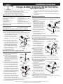
Standard Rim Tank Mounting (All Models):
1. Slide both C-shaped brackets into the valve housing as shown
(see Figure 4).
Note: Use the upper mounting
holes in the valve housing to
maintain a water level about 4”
below the rim. Use the lower
mounting holes in the valve
housing to maintain a water level
about 2-3/8” below the rim.
2. Attach each C-shaped bracket to
the valve housing with the 3/8”
mounting screws.
3. Apply food grade anti-seize
compound to threads and connect
the water supply line.
4. Position the automatic oat valve assembly over the tank rim.
5. Thread the thumb screws through the C-shaped brackets and tighten.
6. Test automatic oat valve operation.
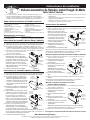
Wide Rim Tank Mounting
(Models TM830T & TM830AS):
1. Slide both L-shaped brackets into the valve housing as shown
(see Figure 5).
2. Attach each L-shaped bracket
to the valve housing with the
3/8” mounting screws.
3. Attach a C-shaped bracket to
each L-shaped bracket with
the 3/8” mounting screws.
Note: There are two positions
on the L-shaped bracket
which allows you to adjust
for varying rim widths.
4. Apply food grade anti-seize
compound to threads and
connect the water supply line.
5. Position the automatic oat valve assembly over the tank rim.
6. Thread the thumb screws through the C-shaped brackets and tighten.
7. Test automatic oat valve operation.
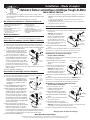
Extra Wide Rim Tank Mounting
(Models TM830T & TM830AS):
1. Slide both L-shaped brackets into
the valve housing as shown
(see Figure 6).
2. Attach each L-shaped bracket to
the valve housing with the 3/8”
mounting screws.
3. Apply food grade anti-seize
compound to threads and
connect the water supply line.
4. Position the automatic oat
valve assembly over the tank
rim.
5. Attach each L-shaped bracket to
the tank rim with two (2) self tapping screws.
Note: Pre-drill the tank rim at the desired automatic oat valve mounting
location with a 1/8” drill if necessary.
6. Test automatic oat valve operation.
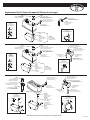
1. Familiarize yourself with all of the automatic oat valve components.
a. Open the loose parts bag and inventory the contents.
b. The plastic orice insert and hose washer is already assembled in the
valve housing. Make sure the orice insert and washer are rmly
seated against the valve housing.
c. The rubber valve seat is already
pinned to the oat. Make sure the
seat and pin are rmly seated against
the oat.
2. Position the oat assembly inside
the valve housing and slide the large
2-1/4” cotter pin through the housing
and the oat assembly (see Figure 1).
Spread the ends of the large cotter
pin open slightly with pliers. When
properly installed, the oat assembly
should pivot freely on the cotter pin
inside the valve housing.
3.
See Mounting Instructions.
FLOAT
ASSEMBLY
VALVE
HOUSING
LARGE
COTTER
PIN
RUBBER
VALVE SEAT
C-SHAPED
BRACKET
3/8”
MOUNTING
SCREW
THUMB
SCREW
VALVE
HOUSING
C-SHAPED
BRACKET
L-SHAPED
BRACKET
3/8”
MOUNTING SCREW
3/8”
MOUNTING
SCREW
THUMB
SCREW
VALVE
HOUSING
L-SHAPED
BRACKET
SELF TAPPING SCREWS
3/8”
MOUNTING
SCREW
VALVE
HOUSING
MANUAL
Installation Instructions
Trough-O-Matic Automatic Metal Float Valve
TM830/TM830T/TM830AS
• Sturdy adjustable brackets tighten down with thumb screws and make
installation on edge of troughs and tanks fast and easy.
• Accepts standard 3/4” garden hose thread. Direct pipe installation
quickly achieved with 3/4” adapter (not included).
• One piece oat molded from durable maintenance free polyethylene.
• Adjustable neoprene valve seat delivers long life (Models TM830 &
TM830T).
• Longer oat leverages up to 55 psi water pressure with 245 gallons per
hour capacity.
1 Metal Valve Housing
1 Plastic Orice Insert (already assembled)
1 Hose Washer (already assembled)
1 Float Assembly
1 Large Cotter Pin 1/8” x 2-1/4”
2 C-Shaped Brackets
2 Thumb Screws 1/4”-20 x 2”
2 Mounting Screws 1/4”-20 x 3/8” (TM830)
4 Mounting Screws 1/4”-20 x 3/8”
(TM830T &TM830AS)
2 L-Shaped Brackets (TM830T & TM830AS)
4 Self Tapping Screws #10 x 3/4”
(TM830T & TM830AS)
1 Anti-Siphon Valve Stem (TM830AS)
1 Anti-Siphon Valve Housing (TM830AS)
1 Small Cotter Pin 1/8” x 1-1/8”
(TM830AS)
Straight Blade Screw Driver
Phillips Head Screw Driver
Needle Nose Pliers
Food Grade Anti-Seize Compound
1. Familiarize yourself with all of the automatic oat valve components.
a. Open the loose parts bag and inven-
tory the contents.
b. The plastic orice insert and hose
washer is already assembled in the
anti-siphon valve housing. Make
sure the orice insert and washer are
rmly seated against the anti-siphon
valve housing.
2. Position the anti-siphon valve stem as-
sembly in the slot of the oat and slide
the 1-1/8” cotter pin (smallest of the
two cotter pins) through the oat and
the valve stem assembly (see Figure
2) then spread the end of the cotter pin
open slightly. When properly installed,
the valve stem assembly should pivot
freely on the cotter pin inside the oat.
3. Thread the anti-siphon valve housing all
the way into the valve housing.
4. Position oat assembly inside valve
housing and slide the large 2-1/4”
cotter pin through the housing and the
oat assembly (see Figure 3). Spread
the ends of the large cotter pin open
slightly with pliers. When properly installed, the oat assembly should
pivot freely on the cotter pin inside the valve housing.
5.
See Mounting Instructions.
Each Automatic Float Valve Contains:
Tools Required:
Assembly Instructions
(Models TM830 & TM830T):
Assembly Instructions
(Models TM830AS):
Mounting Instructions:
Figure 1
FLOAT
ANTI-SIPHON
VALVE STEM
SMALL
COTTER
PIN
FLOAT
ASSEMBLY
VALVE
HOUSING
LARGE
COTTER
PIN
ANTI-SIPHON
VALVE HOUSING
Figure 4
Figure 5
Figure 6
1450 West 13th Street • Glencoe, MN 55336 • Customer Service 800-260-0888 • FAX 651-982-5101
For additional information visit www.miller-mfg.com
Figure 2
Figure 3

Miller Manufacturing Company
1450 West 13th Street • Glencoe, MN 55336 • Customer Service 800-260-0888 • FAX 651-982-5101
Si desea obtener más información visite www.miller-mfg.com
MANUAL
Instrucciones de instalación
1 alojamiento de válvula de metal
1 accesorio de oricio de plástico
(ya ensamblados)
1 arandela de manguera (ya ensamblados)
1 conjunto de otador
1 chaveta grande de 1/8” x 2 1/4”
2 soportes en C
2 tornillos de mariposa de 1/4”-20 x 2”
2 tornillos de montaje de 1/4”-20 x 3/8” (TM830)
4 tornillos de montaje de 1/4”-20 x 3/8”
(TM830T y TM830AS)
2 soportes en L (TM830T y TM830AS)
4 tornillos autorroscantes n.º 10 x 3/4”
(TM830T y TM830AS)
1 vástago de válvula antisifónica (TM830AS)
1 alojamiento de válvula antisifónica
(TM830AS)
1 chaveta pequeña de 1/8” x 1 1/8” (TM830AS)
Montaje en depósito de borde estándar (Todos los modelos):
1. Deslice e introduzca los dos soportes en C en el alojamiento de la válvula
según se ilustra (ver la gura 4).
Nota: Use los oricios de montaje
superiores del alojamiento de la válvula
para mantener un nivel de agua unas
4” (10 cm) por debajo del borde. Use
los oricios de montaje inferiores
del alojamiento de la válvula para
mantener un nivel de agua unas 2 3/8”
(11 cm) por debajo del borde.
2.
Coloque cada soporte en C en el
alojamiento con los tornillos de
montaje de 3/8”.
3. Conecte la tubería de suministro de agua.
4.
Ubique el conjunto de válvula automática de otador sobre el borde del depósito.
5.
Enrosque los tornillos de mariposa en los soportes en C y ajústelos.
6. Compruebe el funcionamiento de la válvula de otador.
Montaje en depósito de borde ancho
(Modelos TM830T y TM830AS):
1
. Deslice e introduzca los dos soportes en L en el alojamiento de la válvula
según se ilustra (ver la gura 5).
2. Coloque cada soporte en L en el
alojamiento con los tornillos de
montaje de 3/8”.
3. Coloque cada soporte en C en cada
soporte en L con los tornillos de
montaje de 3/8”.
Nota: El soporte en L tiene dos
posiciones que le permiten adaptarlo
a bordes de distintos anchos.
4. Conecte la tubería de suministro de
agua.
5. Ubique el conjunto de válvula automática de otador sobre el borde del
depósito.
6. Enrosque los tornillos de mariposa en los soportes en C y ajústelos.
7.
Compruebe el funcionamiento de la válvula de otador.
Montaje en depósito de borde extra ancho
(Modelos TM830T y TM830AS):
1.
Deslice e introduzca los dos soportes en L en el alojamiento de la válvula
según se ilustra (ver la gura 6).
2. Coloque cada soporte en L en el
alojamiento con los tornillos de
montaje de 3/8”.
3. Conecte la tubería de suministro de
agua.
4. Ubique el conjunto de válvula
automática de otador sobre el borde
del depósito.
5. Coloque cada soporte en L en el borde
del depósito con dos (2) tornillos
autorroscantes.
Nota: Perfore previamente el borde del depósito en el lugar de montaje
deseado de la válvula de otador con un taladro de 1/8” de ser necesario.
6.
Compruebe el funcionamiento de la válvula de otador.
1.
Familiarícese con todos los componentes de la válvula automática de otador.
a. Abra la bolsa de piezas sueltas y haga una lista detallada del contenido.
b. El accesorio de oricio de plástico y la arandela de manguera ya vienen
ensamblados en el alojamiento de la válvula. Compruebe que el accesorio de
oricio y la arandela estén bien asentados contra el alojamiento de la válvula.
c.
El asiento de válvula de goma ya viene unido al otador. Compruebe
que el asiento y el pasador estén bien
apoyados contra el otador.
2.
Ubique el conjunto de otador dentro del
alojamiento de la válvula y haga pasar la
chaveta grande de 2-1/4” por el alojamiento y
el conjunto de otador (ver la gura 1). Abra
ligeramente los extremos de la chaveta grande
separándolos con los alicates. Si está cor-
rectamente instalado, el conjunto de otador
debe girar libremente en la chaveta dentro del
alojamiento de la válvula.
3. Consulte las instrucciones de montaje.
KIT
DE FLOTADOR
ALOJAMIENTO
DE VÁLVULA
CHAVETA
GRANDE
ASIENTO DE VÁLVULA
DE GOMA
SOPORTE EN C
TORNILLO
DE MONTAJE
DE 3/8”
TORNILLO
DE MARIPOSA
ALOJAMIENTO
DE VÁLVULA
SOPORTE
EN C
SOPORTE EN L
TORNILLO
DE MONTAJE
DE 3/8”
TORNILLO
DE MONTAJE
DE 3/8”
TORNILLO
DE MARIPOSA
ALOJAMIENTO
DE VÁLVULA
TORNILLO AUTORROSCANTE
SOPORTE EN L
TORNILLO
DE MONTAJE
DE 3/8”
ALOJAMIENTO
DE VÁLVULA
Válvula automática de flotador metal Trough-O-Mat
ic
TM830/TM830T/TM830AS
• Los robustos soportes ajustables se jan con tornillos de mariposa y per-
miten una instalación rápida y sencilla en el borde de cubas y depósitos.
• Admite roscas de manguera de jardín estándar de 3/4”. La instalación directa
en tubos se realiza con rapidez con un adaptador de 3/4” (no se incluye).
• Flotador en una sola pieza moldeado en polietileno duradero que no necesita
mantenimiento.
• El asiento de válvula de neopreno ajustable ofrece una prolongada vida útil
(Modelos TM830 y TM830T).
• El otador más largo aprovecha hasta 55 psi de presión de agua con una
capacidad de 245 galones (927 litros) por hora.
Destornillador de hoja recta
Destornillador Phillips
1.
Familiarícese con todos los componentes de la válvula automática de otador.
a. Abra la bolsa de piezas sueltas y haga una lista detallada del contenido.
b.
El accesorio de oricio de plástico y la
arandela de manguera ya vienen ensam-
blados en el alojamiento de la válvula
antisifónica. Compruebe que el accesorio
de oricio y la arandela estén bien asen-
tados contra el alojamiento de la válvula
antisifónica.
2. Enrosque por completo el alojamiento de
la válvula antisifónica en el alojamiento
de la válvula.
3.
Ubique el conjunto de vástago de la válvula
antisifónica en la ranura del otador y haga
pasar la chaveta de 1 1/8” (la más pequeña
de las dos chavetas) por el otador y el
conjunto de vástago de la válvula (ver la
gura 2), y abra ligeramente el extremo de la
chaveta. Si está correctamente instalado, el
conjunto de vástago de la válvula debe girar
libremente en la chaveta dentro del otador.
4.
Ubique el conjunto de otador dentro del
alojamiento de la válvula y haga pasar la
chaveta grande de 2-1/4” por el alojamiento y
el conjunto de otador
(ver la gura 3).
Abra
ligeramente los extremos de la chaveta grande separándolos con los alicates.
Si
está correctamente instalado, el conjunto de otador debe girar libremente en
la chaveta dentro del alojamiento de la válvula.
5.
Consulte las instrucciones de montaje.
Cada válvula automática de flotador contiene:
Herramientas necesarias:
Instrucciones de ensamble (Modelos TM830 y TM
830T):
Instrucciones de ensamble
(Modelos TM830AS):
En la página 4 encontrará información sobre las piezas de repuesto.
Instrucciones de montaje:
Figura 1
VÁSTAGO
DE VÁLVULA
ANTISIFÓNICA
CHAVETA
PEQUEÑA
KIT
DE FLOTADOR
ALOJAMIENTO
DE VÁLVULA
ALOJAMIENTO
DE VÁLVULA
ANTISIFÓNICA
KIT
DE FLOTADOR
CHAVETA
GRANDE
Figura 4
Figura 5
Figura 6
Figura 2
Figura 3
Alicates de punta na
Compuesto de Anti-Agarra de Grado de alimento

MANUAL
Installation – Mode d’emploi
Miller Manufacturing Company
1450 West 13th Street • Glencoe, MN 55336 • Customer Service 800-260-0888 • FAX 651-982-5101
Pour obtenir des informations complémentaires connectez-vous au site www.miller-mfg.com
1 boîtier de robinet métallique
1 insert d’orice en plastique (déjà montés)
1 rondelle pour exible (déjà montés)
1 groupe otteur
1 grande goupille fendue 1/8” x 2-1/4”
2 étriers de xation
2 vis à tête à clé de violon 1/4” - 20 x 2”
4 vis de xation 1/4” - 20 x 3/8”
(TM830T & TM830AS)
2 vis de xation 1/4” - 20 x 3/8” (TM830)
2 pattes de xation en L
(TM830T & TM830AS)
4 vis autotaradeuses n° 10 x 3/4”
(TM830T & TM830AS)
1 tige de vanne anti-siphon (TM830AS)
1 logement de vanne anti-siphon (TM830AS)
1 petite goupille fendue 1/8” x 1-1/8”
(TM830AS)
Installation sur un réservoir à bord standard (tous modèles):
1. Insérez les deux étriers dans le boîtier du robinet en suivant l’illustration
(voir gure 4).
Remarque: Si vous utilisez les
trous supérieurs du boîtier de
robinet, vous obtiendrez un niveau
d’eau à 4” du bord environ. Avec
les trous inférieurs, l’eau arrivera
approximativement à 2-3/8” du bord.
2. Fixez l’étrier au boîtier du robinet avec
les vis de xation de 3/8”.
3. Branchez la conduite d’alimentation
en eau.
4. Placez le robinet automatique à otteur sur le bord du réservoir.
5. Insérez les vis à tête à clé de violon dans les étriers puis serrez.
6. Testez le fonctionnement du robinet automatique à otteur.
Installation sur un réservoir à bord large
(modèles TM830T & TM830AS):
1. Insérez les deux pattes en L dans le boîtier du robinet en suivant
l’illustration (voir gure 5).
2. Fixez chaque patte en L au boîtier
du robinet avec les vis de xation
de 3/8”.
3. Fixez un étrier à chaque patte en L à
l’aide des vis de xation de 3/8”.
Remarque: Les deux positions
de xation de la patte en L vous
permettent de monter le robinet sur
des bords de différentes largeurs.
4. Branchez la conduite d’alimentation
en eau.
5. Placez le robinet automatique à otteur sur le bord du réservoir.
6. Insérez les vis à tête à clé de violon dans les étriers puis serrez.
7. Testez le fonctionnement du robinet automatique à otteur.
Installation sur un réservoir à bord extra-large
(modèles TM830T & TM830AS):
1. Insérez les deux pattes en L dans
le boîtier du robinet en suivant
l’illustration (voir gure 6).
2. Fixez chaque patte en L au boîtier du
robinet avec les vis de xation de 3/8”.
3. Branchez la conduite d’alimentation
en eau.
4. Placez le robinet automatique à otteur
sur le bord du réservoir.
5. Fixez chaque patte en L au bord du
réservoir avec deux vis autotaradeuses (2).
Remarque: Si nécessaire, prépercez avec un foret de 1/8”le bord du réservoir
à l’emplacement où vous désirez installer le robinet.
6. Testez le fonctionnement du robinet automatique à otteur.
1. Passez en revue l’ensemble des composants du robinet automatique à otteur.
a. Ouvrez le sac de pièces détachées et faites l’inventaire de son contenu.
b. L’insert d’orice en plastique et la rondelle pour exible sont déjà montés
dans le boîtier du robinet. Assurez-vous que l’insert et la rondelle sont bien
en contact avec le boîtier du robinet.
c. Le siège de vanne en caoutchouc est déjà
rattaché au otteur par une goupille.
Assurez-vous que le siège et la goupille
sont bien en contact avec le otteur.
2. Placez le groupe otteur à l’intérieur du boî-
tier de robinet puis faites glisser la grande
goupille fendue de 2 pouces ¼ à travers
le boîtier et le groupe otteur (voir gure
1). Écartez légèrement les extrémités de la
grande goupille fendue à l’aide des pinces.
Lorsqu’il est correctement monté, le groupe
otteur doit pivoter librement autour de la goupille fendue à l’intérieur du
boîtier de robinet.
3. Voir les instructions d’installation.
GROUPE
FLOTTEUR
BOITIER
DU ROBINET
GRANDE
GOUPILLE
FENDUE
ETRIER
VIS DE FIXATION
DE 3/8”
VIS A TETE
A CLE DE VIOLON
BOITIER
DU ROBINET
PATTE EN L
ETRIER
VIS
DE FIXATION
DE 3/8”
VIS DE FIXATION
DE 3/8”
VIS A TETE
A CLE DE VIOLON
BOITIER
DU ROBINET
VIS AUTOTARADEUSE
PATTE EN L
VIS
DE FIXATION
DE 3/8”
BOITIER
DU ROBINET
Robinet à flotteur automatique métallique Trough-O-Matic
TM830/TM830T/TM830AS
• Des supports résistants et réglables se serrent avec des vis à tête à clé de
violon, ce qui permet une installation simple et rapide sur le rebord des auges
et des réservoirs.
• Flotteur monobloc en polyéthylène longue durée sans entretien.
• Conçu pour les exibles d’arrosage présentant un letage 3/4” standard. Un
adaptateur 3/4” (non fourni) permet de brancher directement et rapidement
un tuyau.
• Le siège de vanne ajustable en néoprène offre une longue durée de vie
(modèles TM830 & TM830T).
• Le long otteur résiste à une pression allant jusqu’à 55 psi et à un débit de
245 gallons (927 litres) par heure.
Tournevis plat
Tournevis cruciforme
1. Passez en revue l’ensemble des composants du robinet automatique à otteur.
a. Ouvrez le sac de pièces détachées et faites l’inventaire de son contenu.
b. L’insert d’orice en plastique et la rondelle
pour exible sont déjà montés dans le
boîtier de la vanne anti-siphon. Assurez-
vous que l’insert et la rondelle sont bien
en contact avec le boîtier de la vanne
anti-siphon.
2. Vissez le boîtier de la vanne anti-siphon
jusqu’au fond du boîtier de vanne.
3. Placez la tige de la vanne anti-siphon dans
la fente du otteur puis faites glisser la
goupille fendue de 1-1/8” (la plus petite
des deux goupilles fendues) à travers le
otteur et la tige de la vanne (voir gure
2). Ouvrez ensuite légèrement l’extrémité
de la goupille. Lorsqu’il est correctement
monté, le groupe tige de vanne doit pivoter
sans accrocher autour de la goupille fendue
à l’intérieur du otteur.
4.
Placez le groupe otteur à l’intérieur du
boîtier de robinet puis faites glisser la grande
goupille fendue de 2 pouces ¼ à travers le
boîtier et le groupe otteur (voir gure 3).
Écartez légèrement les extrémités de la grande goupille fendue à l’aide des
pinces. Lorsqu’il est correctement monté, le groupe otteur doit pivoter sans
accrocher autour de la goupille fendue à l’intérieur du boîtier de robinet.
5. Voir les instructions d’installation.
Un robinet automatiqu e à flotteur comprend:
Outils nécessaires :
Instructions de montage (modèles TM830 et TM 830T):
Instructions de montage (modèles TM830AS):
Voir page 4 pour les pièces de rechange.
Instructions d’installation:
Figure 1
TIGE DE LA VANNE
ANTI-SIPHON
GROUPE
FLOTTEUR
PETITE
GOUPILLE
FENDUE
BOITIER DE VANNE
ANTI-SIPHON
BOITIER
DU ROBINET
GRANDE
GOUPILLE
FENDUE
GROUPE
FLOTTEUR
Figure 4
Figure 5
Figure 6
Figure 2
Figure 3
Pinces à bec eflé
Le Composé d’Anti-Saisit de Degré de nourriture

Replacement Parts*/Piezas de repuesto*/Pièces de rechange*
Model TM830
Model TM830T
Model TM830AS
T832P*
PLASTIC ORIFICE INSERT
ACCESORIO DE ORIFICIO DE PLÁSTICO
INSERT D’ORIFICE EN PLASTIQUE
DART
DARDO
AGRAFE
T826*
VALVE SEAT
ASIENTO DE VÁLVULA
SIEGE DE VANNE
FLOAT
FLOTADOR
FLOTTEUR
T809KIT*
FLOAT ASSEMBLY
KIT DE FLOTADOR
GROUPE FLOTTEUR
T828*
HOSE WASHER
ARANDELA DE MANGUERA
RONDELLE POUR FLEXIBLE
2-1/4” COTTER PIN
CHAVETA DE 2-1/4”
GOUPILLE FENDUE DE 2-1/4 ”
3/8” MOUNTING SCREW (2)
TORNILLO DE MONTAJE DE 3/8” (2)
VIS DE FIXATION DE 3/8” (2)
THUMB SCREW (2)
TORNILLO DE MARIPOSA (2)
VIS A TETE A CLE DE VIOLON (2)
CT805*
C-SHAPED BRACKET (2)
SOPORTE EN C (2)
ETRIER (2)
3/8” MOUNTING SCREW (2)
TORNILLO DE MONTAJE DE 3/8” (2)
VIS DE FIXATION DE 3/8” (2)
SELF TAPPING SCREW (4)
TORNILLO AUTORROSCANTE (4)
VIS AUTOTARADEUSE (4)
L-SHAPED BRACKET (2)
SOPORTE EN L (2)
PATTE EN L (2)
THUMB SCREW (2)
TORNILLO DE MARIPOSA (2)
VIS A TETE A CLE DE VIOLON (2)
C-SHAPED BRACKET (2)
SOPORTE EN C (2)
ETRIER (2)
(2)
(4)
(1)
(2)
(1)
(1)
(1)
T825ASKIT*
PARTS KIT
KIT DE PIEZAS
KIT DE PIECES DETACHEES
T825KIT*
PARTS KIT
KIT DE PIEZAS
KIT DE PIECES DETACHEES
(2)
(2)
(2)
(2)
(2)
(4)
(2)
T825TKIT*
PARTS KIT
KIT DE PIEZAS
KIT DE PIECES DETACHEES
SELF TAPPING SCREW (4)
TORNILLO AUTORROSCANTE (4)
VIS AUTOTARADEUSE (4)
L-SHAPED BRACKET (2)
SOPORTE EN L (2)
PATTE EN L (2)
3/8” MOUNTING SCREW (2)
TORNILLO DE MONTAJE DE 3/8” (2)
VIS DE FIXATION DE 3/8” (2)
THUMB SCREW (2)
TORNILLO DE MARIPOSA (2)
VIS A TETE A CLE DE VIOLON (2)
C-SHAPED BRACKET (2)
SOPORTE EN C (2)
ETRIER (2)
T810AS*
VALVE STEM
VÁSTAGO DE VÁLVULA
TIGE DE VANNE
T809AS*
FLOAT
FLOTADOR
FLOTTEUR
2-1/4” COTTER PIN
CHAVETA DE 2-1/4”
GOUPILLE FENDUE DE 2-1/4 ”
T808M*
1-1/8” COTTER PIN
CHAVETA DE 1-1/8”
GOUPILLE FENDUE DE 1-1/8 ”
3/8” MOUNTING SCREW (2)
TORNILLO DE MONTAJE DE 3/8” (2)
VIS DE FIXATION DE 3/8” (2)
T826AS*
VALVE SEAT
ASIENTO DE VÁLVULA
SIEGE DE VANNE
(1)
(1)
(1)
(1)
(1)
(1)
TOMASKIT*
REPAIR KIT
KIT DE REPARACIÓN
KIT DE REPARATION
T811AS*
ANTI-SIPHON VALVE HOUSING
CAJA DE LA VÁLVULA ANTI-SIFÓN
BOÎTIER ANTI-SIPHON
T828*
HOSE WASHER
ARANDELA DE MANGUERA
RONDELLE POUR FLEXIBLE
PLASTIC ORIFICE INSERT
ACCESORIO DE ORIFICIO DE PLÁSTICO
INSERT D’ORIFICE EN PLASTIQUE
TOMKIT*
REPAIR KIT
KIT DE REPARACIÓN
KIT DE REPARATION
(4)
(4)
(4)
(4)
(4)
TOMKIT*
REPAIR KIT
KIT DE REPARACIÓN
KIT DE REPARATION
(4)
(4)
(4)
(4)
(4)
171175_05/18
Miller Manufacturing, Glencoe, MN 55336 USA •www.miller-mfg.com
-
 1
1
-
 2
2
-
 3
3
-
 4
4


