
CP34, CP35 AND CP37 SERIES
INTENDED FOR DOMESTIC COOKING ONLY
INSTALLER: LEAVE THIS MANUAL WITH HOMEOWNER.
HOMEOWNER: USE AND CARE INFORMATION ON PAGES 12 and 13.
BEST; Hartford, Wisconsin www.BestRangeHoods.com 800-558-1711
REGISTER YOUR PRODUCT ON LINE AT: www.BestRangeHoods.com/register
For additional information - visit www.BestRangeHoods.com
SV08544 rev. G
HB0078
INSTALLATION INSTRUCTIONS
READ AND SAVE THESE INSTRUCTIONS
!
!

WARNING WARNING
- 2 -
TO REDUCE THE RISK OF FIRE, ELECTRIC
SHOCK OR INJURY TO PERSONS, OBSERVE THE
FOLLOWING:
1. Use this unit only in the manner intended by the
manufacturer. If you have questions, contact the
manufacturer at the address or telephone number
listed in the warranty.
2. Before servicing or cleaning unit, switch power off at
service panel and lock service disconnecting means
to prevent power from being switched on accidentally.
When the service disconnecting means cannot be
locked, securely fasten a prominent warning device,
such as a tag, to the service panel.
3. Installation work and electrical wiring must be done
by qualified personnel in accordance with all
applicable codes and standards, including fire-rated
construction codes and standards.
4. Sufficient air is needed for proper combustion and
exhausting of gases through the flue (chimney) of fuel
burning equipment to prevent backdrafting. Follow the
heating equipment manufacturer’s guidelines and
safety standards such as those published by the
National Fire Protection Association (NFPA) and the
American Society for Heating, Refrigeration and Air
Conditioning Engineers (ASHRAE) and the local code
authorities.
5. When cutting or drilling into wall or ceiling, do not
damage electrical wiring and other hidden utilities.
6. Ducted fans must always be vented to the outdoors.
7. Do not use this unit with any solid-state speed control
device.
8. To reduce the risk of fire, use only metal ductwork.
9. This unit must be grounded.
10. When applicable local regulations comprise more
restrictive installation and/or certification requirements,
the aforementioned requirements prevail on those of
this document and the installer agrees to conform to
these at his own expenses.
TO REDUCE THE RISK OF A RANGE TOP
GREASE FIRE:
a) Never leave surface units unattended at high
settings. Boilovers cause smoking and greasy
spillovers that may ignite. Heat oils slowly on low or
medium settings.
b) Always turn hood ON when cooking at high heat or
when flambeing food (i.e.: Crêpes Suzette, Cherries
Jubilee, Peppercorn Beef Flambé).
c) Clean ventilating fans frequently. Grease should not
be allowed to accumulate on fan or filter.
d) Use proper pan size. Always use cookware
appropriate for the size of the surface element.
TO REDUCE THE RISK OF INJURY TO PERSONS IN
THE EVENT OF A RANGE TOP GREASE FIRE,
OBSERVE THE FOLLOWING*:
1. SMOTHER FLAMES with a close-fitting lid, cookie
sheet or metal tray, then turn off the burner. BE
CAREFUL TO PREVENT BURNS. IF THE FLAMES
DO NOT GO OUT IMMEDIATELY, EVACUATE AND
CALL THE FIRE DEPARTMENT.
2. NEVER PICK UP A FLAMING PAN — You may be
burned.
3. DO NOT USE WATER, including wet dishcloths or
towels —This could cause a violent steam explosion.
4. Use an extinguisher ONLY if:
A. You own a Class ABC extinguisher and you know
how to operate it.
B. The fire is small and contained in the area where
it started.
C. The fire department has been called.
D. You can fight the fire with your back to an exit.
* Based on “Kitchen Fire Safety Tips” published by NFPA.
CAUTION
1. For indoor use only.
2. For general ventilating use only. Do not use to exhaust
hazardous or explosive materials and vapors.
3. To avoid motor bearing damage and noisy and/or
unbalanced impellers, keep drywall spray, construction
dust, etc. off power unit.
4. Your insert motor has a thermal overload which will
automatically shut off the motor if it becomes
overheated. The motor will restart when it cools down.
If the motor continues to shut off and restart, have the
insert serviced.
5. The minimum hood distance above cooktop must not
be less than 24”. A maximum of 30” above cooktop is
recommended for best capture of cooking impurities.
6. Two installers are recommended because of the large
size and weight of this unit.
7. To reduce the risk of fire and to properly exhaust air,
be sure to duct air outside — Do not exhaust air into
spaces within walls or ceiling or into attics, crawl
space or garage.
8. This product is equipped with a thermostat which may
start blower automatically. To reduce the risk of injury
and to prevent power from being switched on
accidentally, switch power off at service panel and
lock or tag service panel.
9. Because of the high exhausting capacity of this unit,
you should make sure enough air is entering the
house to replace exhausted air by opening a window
close to or in the kitchen.
10. To reduce the risk of fire and electrical shock, the Best
models CP34, CP35 and CP37 Series should only be
installed with their own built-in blowers. Other blowers
cannot be substituted.
11. Please read specification label on product for further
information and requirements.
!
!

HL0122
- 3 -
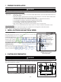
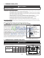
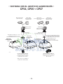
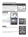
- CP34, CP35 AND CP37 POWER PACK SYSTEMS -
8” ROUND
ADJUSTABLE ELBOW
CP37
POWER PACK
CP35
POWER PACK
M
ODEL 634 OR 644
(R
OOF CAP)
M
ODEL 643
(8” R
OUND WALL CAP)
8” R
OUND
STANDARD DUCT
ADAPTER AND DAMPER
8” ROUND (SUPPLIED WITH
SINGLE BLOWER POWER PACKS
)
M
ODEL 437
(H
IGH CAPACITY
ROOF CAP
)
M
ODEL 441
(10’’ R
OUND
WALL CAP
)
M
ODEL 410
(10” R
OUND DUCT
— 2 FT. SECTIONS)
M
ODEL 418
(10” ROUND
ADJUSTABLE ELBOW
)
10” R
OUND VERTICAL
IN
-LINE DAMPER (SUPPLIED WITH
DUAL BLOWER POWER PACK
)
D
UAL BLOWER (1200 CFM)
SUPPLIED WITH 48” WIDTH
POWER PACK ONLY
SINGLE BLOWER (600 CFM)
SUPPLIED WITH 30’’, 36’’ AND
42” WIDTH POWER PACK ONLY
10” ROUND ADAPTER
(SUPPLIED WITH DUAL BLOWER
POWER PACK)
CP34
POWER PACK*
*300
CFM AIR FLOW REDUCER
INTEGRATED ON CP34 MODEL

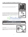
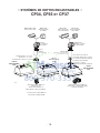
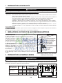
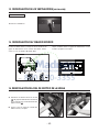
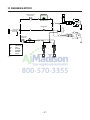
2. INSTALL DUCTWORK AND ELECTRICAL WIRING
Plan where and how the ductwork will be installed. Access to the top of the
hood is preferred for connection of ductwork.
Install proper-sized ductwork, elbows and roof or wall cap for the type of blower
you are installing. If installing CP34 or CP35 power pack, use 8” round
ductwork and if installing CP37 power pack, use 10” round ductwork. Use
2” metal foil duct tape to seal duct joints.
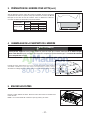
The minimum hood distance above cooktop must not be less than 24”.
A maximum of 30” above cooktop is recommended for best capture of
cooking impurities.
Distances over 30” are at the installer and users discretion.
Run 3-wire power supply cable to installation location. Its length should extend
at least 4 feet below the bottom of the custom hood.
Power pack
Roof cap
Wall
cap
HH0101A
8” round duct for CP34 & CP35
or 10” round duct for CP37
8” round adapter & damper
for CP34 & CP35 or
10” round adapter for CP37
24” to 30”
above
cooking surface
8” round elbow for CP34 & CP35
or 10” round elbow for CP37
10” in line
vertical damper for CP37
MODELS CP34 & CP35 (SINGLE BLOWER)
OR CP37 (DUAL BLOWER)
TYPICAL DUCTWORK
1. PREPARE THE INSTALLATION
Make sure that the following items are included:
- Power Pack
- Accessories: • Baffle filters: CP34 and CP35: 3 for the 30’’ and 36’’ width models, 4 for the 42’’ width model; CP37: 5 for
this 48’’ width model
• Baffle filters handles (taped inside the power pack): CP34 and CP35: 3 for the 30’’ and 36’’ width models,
4 for the 42’’ width model; CP37: 5 for this 48’’ width model
• 2 Shielded halogen lamps (120 V, 50 W, MR16 with GU10 base or PAR16 with GU10 base)
• 8” round adapter and damper (included with single blower power packs)
• 10” round in-line vertical damper (included with dual blower power pack)
• 10” round adapter (included with dual blower power pack)
• Bag of parts including: (1) wire clamp, (2) wire connectors, (4) no. 8 x 3/8” screws,
(9) no. 8 x 1/2” chrome plated screws, (10) no. 8-32 x 1/4” screws. If need be, discard extra screws.
Parts sold separately:
- Ducts, elbows, wall and roof caps. Refer to page 3 for a complete list of venting options and model numbers.
NOTE: During installation, protect countertop and/or cooktop.
WARNING
When performing installation, servicing or cleaning the unit, it is recommended to wear safety glasses and gloves.
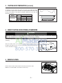
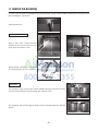
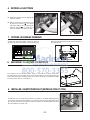
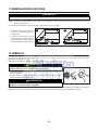
3. CUSTOM HOOD PREPARATION
WARNING
When building a custom hood, always follow all applicable construction codes and standards.
!
The custom hood must be constructed to fit the size and shape of the CP34, CP35 or the CP37 power pack models.
See chart and illustration for details.
* Dimensions A and B include rivets head.
A
B
C
7/8
”
4½”
HD0296A
C
L
12”
3”
REAR
FRONT
- 4 -
POWER PACK MODELS
WIDTH
TOTAL
WEIGHT
RANGE HOOD DIMENSIONS
A* B* C
CP34 & CP35
30” 33 LB 19
5
⁄16” 28
7
⁄16” 4
7
⁄8”
36” 37.2 LB 19
5
⁄16” 34
7
⁄16” 4
7
⁄8”
42” 41.6 LB 19
5
⁄16” 40
7
⁄16” 4
7
⁄8”
CP37 48” 56.5 LB 22
9
⁄16” 46
7
⁄16” 5
7
⁄8”
!

- 5 -
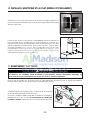
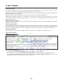
4. MOUNT CUSTOM HOOD INTERNAL FRAMEWORK
5. REMOVE FILTERS
HD0295
Since the CP34, CP35 and CP37 power pack models mounting holes are
located in front and rear sides (see illustration beside), plan to install wood frame
at front and sides for support.
HH0102A
The CP34, CP35 and CP37 power pack models are supported by the custom hood internal framework with screws provided in
parts bag.
WARNING
The framework must be positively secured to wall studs or other wooden framework behind the drywall.
Make sure it is capable of supporting its own weight and the weight of the CP34, CP35 or CP37. Failure to
do so may cause personal injury or damage to countertop or cooktop.
!
Remove tape on filters. Remove filters from power pack and set aside.
NOTE: It is recommended to start with the center one(s).
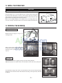
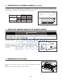
To minimize the gap around the power pack, take actual width and depth
measurements of power pack and add 1/16” to get D and E measurements. Cut
the hole in the bottom of the cabinet according to dimensions. See chart and
illustration for details.
E
HD0367
D
3. CUSTOM HOOD PREPARATION (CONTINUED)
POWER PACK
MODELS
WIDTH
CUTOUT DIMENSIONS
D E
CP34 & CP35
30” 19
3
⁄8” 28½”
36” 19
3
⁄8” 34½”
42” 19
3
⁄8” 40½”
CP37 48” 22
5
⁄8” 46½”

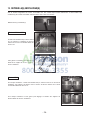
8. REMOVE THE KNOCK-OUT OPENING
From inside the power pack, remove the wiring cover by removing two (2) retaining
screws and set aside. Punch out the electrical knockout hole on top of the power pack.
Install the wire clamp (included in parts bag).
HR0027
9. INSTALL THE ADAPTER/DAMPER (CP34 AND CP35 MODELS)
Using (4) no. 8 x 3/8” screws from parts bag, assemble the adapter/damper on the top
of the power pack. To ensure proper opening of the dampers, remove shipping tape if
present. Seal all joints with metal foil duct tape to eliminate air leaks.
HJ0016
MOUNTING SCREW LOCATION
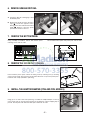
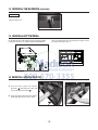
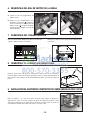
7. REMOVE THE BOTTOM PANEL
Using a Phillips screwdriver, remove both bottom panel
retaining screws and set aside.
Disassemble bottom panel from power pack and set aside.
HO0111
HO0110
RETAINING SCREW LOCATION
- 6 -
SIDE VIEW
6. REMOVE GREASE DRIP RAIL
A. Lift grease drip rail to disengage it from
the bottom panel.
B. Slide grease rail all the way to the left or
right (
1
) and lift the opposite end to
disengage the other end from the bottom
panel (
2
). Remove it from the power
pack and set aside for later use.
A
B
1
2
HD0291
HD0292

- 7 -
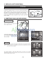
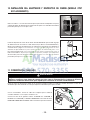
11. CONNECT WIRING
Using the provided wire connectors, connect power pack wires to power
cable into wiring box.
Connect wires as follow: BLACK to BLACK, WHITE to WHITE and GREEN
or BARE wire under ground screw. DO NOT FORGET TO CONNECT THE
GROUND. Reinstall wiring cover.
WARNING
Risk of electrical shock. Electrical wiring must be done by qualified personnel in accordance with all
applicable codes and standards. Before connecting wires, switch power off at service panel and lock
service disconnecting means to prevent power from being switched on accidentally.
!
HE0059
Position the power pack below the installed custom hood. Insert the house wiring cable through the wire clamp previously
installed in step 8. Tighten the wire clamp to secure the cable.
10. INSTALL THE ADAPTER AND THE DAMPER (CP37 MODEL ONLY)
Using (2) no. 8 x 3/8” screws from parts bag, assemble the adapter on the top of the
power pack. Seal all joints with metal foil duct tape to eliminate air leaks.
HJ0026
MOUNTING SCREW LOCATION
Install 10” damper inside the VERTICAL ductwork that will be attached to power pack.
Do not install in a horizontal ductwork or it will not open and close properly. Remove
shipping tape if present. To optimize airflow and quiet sound, position the damper at
least 17” above the top of the CP37 power pack; or as far as the duct run will allow (see
figure beside). Secure the damper to the duct with 3 no. 8 sheet metal screws (not
provided). Check to make sure damper opens and close freely. Seal all joints with metal
foil duct tape to eliminate air leaks.
17” min.
HJ0017A

- 8 -
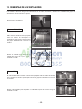
CP37 MODEL
For each blower, using a 5/16” socket, remove all blower mounting screws from the inner
top of the power pack front and rear brackets. Set aside the screws.
HD0297
For each blower, slide it to disengage its flanges from the retaining brackets. Set aside the
blowers.
BLOWERS FRONT BRACKET
BLOWERS REAR BRACKET
HD0298
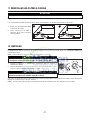
12. REMOVE THE BLOWER(S)
In order to ease the power pack alignment with existing ductwork, unplug and disassemble the blower(s) from the power pack
before installing the custom hood.
HE0085
Unplug the blower(s).
HD0282
RIGHT SIDE
MOUNTING SCREW
LOCATION
Using a 5/16” socket, remove all blower
mounting screws from the inner top of the
power pack. Set aside the screws.
HD0269
LEFT SIDE MOUNTING
SCREW LOCATION
Slide the blower to disengage its flange from
the retaining bracket. Set aside the blower.
HD0270
CP34 AND CP35 MODELS

- 9 -
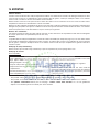
14. REINSTALL THE BLOWER(S)
HD0282
RIGHT SIDE
MOUNTING SCREW
LOCATION
Using a 5/16” socket, secure the blower to
the inner top of the power pack with all blower
mounting screws (previously removed in
step 12).
HD0269
LEFT SIDE MOUNTING
SCREW LOCATION
Slide the blower to engage its flange in the
retaining bracket.
HD0293
CP34 AND CP35 MODELS
CP37 MODEL
For each blower, using a 5/16” socket, secure the blower to the inner top of the power pack
through the front and rear brackets with all blower mounting screws (previously removed
in step 12).
HD0297
For each blower, slide it to engage its flanges in both retaining brackets.
NOTE: Both blowers are identical and can be mounted on either side of the power pack.
BLOWERS FRONT BRACKET
BLOWERS REAR BRACKET
HD0298
13. INSTALL THE POWER PACK
Using provided no. 8 x 1/2” chrome plated screws, install the power pack inside
the custom hood. Start with 2 screws on front corners, then use 4 screws for
sides and use the remaining ones to finalize securing the front power pack. (See
figure beside for mounting screw specific locations.)
Make sure the adapter/damper (or the adapter) enters the ducting. When there
is access to the top of the power pack, seal connections with metal foil duct tape.
CAUTION
Take care not to kink ducting when installing the power pack.
HH0102A

- 10 -
15. REINSTALL BOTTOM PANEL
Lift the bottom panel and engage the power pack metal tabs
in bottom panel slots, as shown in details A and B below.
Secure the bottom panel to the power pack using its screws
previously removed in step 7.
AB
HO0112
HO0110
RETAINING SCREW LOCATION
16. REINSTALL GREASE DRIP RAIL
A. Insert one end of grease rail in power
pack side (
1
) while lifting the other end
over the bottom panel edge (
2
).
B. Center the grease drip rail over the bottom
panel edge and flip it to snap in place.
B
A
1
2
HD0291
HD0292
SIDE VIEW
14. REINSTALL THE BLOWER(S) (CONTINUED)
HE0085
Plug the blower(s) in.
ALL MODELS

- 11 -
17. REINSTALL BAFFLE FILTERS
NOTE: Assemble the metal handles to the filters, using provided no. 8-32 x 1/4” screws, before installing them in the power pack.
It is recommended to install side filters first and finish with center one(s).
1. Insert one end of the filter into the
upper channel of the power pack.
2. Raise the other end toward the
inside of power pack and insert in
the grease drip rail of the power pack.
CAUTION
Remove protective plastic film covering filters before installing them.
1
HD0299
2
18. LIGHT BULBS
This power pack must use shielded halogen lamps (120 V, 50 W, MR16 with GU10 base or PAR16 with GU10 base), included.
NOTE: Before using lamps, remove shipping tape on them (if present).
1. Install the lamps by placing the bulb leads into their grooves in the socket.
2. Gently push upwards and turn clockwise until secure.
To remove lamps, gently push upwards and turn counterclockwise to disengage bulb leads from their grooves.
NOTE: If need be, use a rubber dishwashing glove to add grip when removing the bulb.
WARNING
In order to prevent the risk of personal injury, do not install a lamp
identified for use only in enclosed fixtures.
!
WARNING
In order to prevent the risk of personal injury, the halogen lamps must
be cooled down before removing them.
!
12
HO0090

- 12 -
Hood Cleaning
Stainless steel cleaning:
Avoid: When choosing a detergent
- Any cleaners that contain bleach will attack stainless steel.
- Any products containing: Chloride, fluoride, iodide, bromide will deteriorate surfaces rapidly.
- Any combustible products used for cleaning such as acetone, alcohol, ether, benzol, etc., are highly explosive and should
never be used close to a range.
Do:
• Regularly wash with clean cloth or rag soaked with warm
water and mild soap or liquid dish detergent.
• Always clean in the direction of original polish lines.
• Always rinse well with clear water (2 or 3 times) after
cleaning. Wipe dry completely.
• You may also use a specialized household stainless steel
cleaner.
Don’t:
• Use any steel or stainless steel wool or any other scrapers
to remove stubborn dirt.
• Use any harsh or abrasive cleansers.
• Allow dirt to accumulate.
• Let plaster dust or any other construction residues reach
the hood. During construction/renovation, cover the hood
to make sure no dust sticks to stainless steel surface.
19. USE AND CARE
Baffle Filters
The baffle filters should be cleaned frequently. Use a warm detergent solution. Wash more often if your cooking style generates
greater grease — like frying foods or wok cooking.
Remove baffle filters by pushing them towards the back of hood and rotating filters downward. Baffle filters are dishwasher safe.
Allow filters to dry completely before reinstalling them in the power pack.
Clean all-metal filters in the dishwasher using a non-phosphate detergent. Discoloration of the filter may occur if using phosphate
detergent or as a result of local water conditions — but this will not affect filter performance. This discoloration is not covered
by the warranty.
Rotary Control Knobs
Can be removed for cleaning but first, loosen the set screw using a 1/16” hexagonal key (available at your local hardware store).
Grease Drip Rail
The grease drip rail should be cleaned frequently. Remove it from the power pack (see step 6 on page 5) and use a warm detergent
solution. As with the baffle filters, wash more often if your cooking style generates greater grease — like frying foods or wok
cooking. Allow grease drip rail to dry completely before reinstalling it in the power pack.
Blower(s) Cleaning
Remove the filters in order to access the blower(s). Vacuum blower(s) to clean. Do not immerse in water.

- 13 -
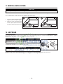
20. OPERATION
Always turn your hood on before you begin cooking to establish an air flow in the kitchen. Let the blower run for a few minutes
to clear the air after you turn off the range. This will help keep the whole kitchen cleaner and brighter.
HEAT SENTRY™
This hood is equipped with a Heat Sentry™ thermostat. This thermostat is a device that will turn on or speed up the blower if it
senses excessive heat above the cooking surface.
1) If blower is OFF - it turns blower ON to HIGH speed.
2) If blower is ON at a lower speed setting – it turns the blower up to HIGH speed.
When the temperature level drops to normal, the blower will return to its original setting.
WARNING
The HEAT SENTRY™ can start the blower even if the hood is turned OFF. In this case, it is impossible to
turn the blower OFF with blower switch. If you must stop the blower, do it from the main electrical panel.
!
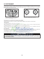
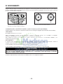
COOKTOP LIGHTING (HALOGEN)
A rotary 3-position knob (1) controls the halogen lights (OFF - low intensity - high intensity).
BLOWER
The blower is operated using two controls.
Use the on/off rocker switch (3) to start and stop the blower. When turned on, the blower operates at the previous setting of the
speed control (2).
Turn the speed control knob counterclockwise to increase blower speed – clockwise to decrease speed.
HC0038
1) H
ALOGEN LIGHT KNOB
2) B
LOWER SPEED CONTROL KNOB
3) ON/OFF
BLOWER SWITCH
2
3
1
HC0039
A) H
ALOGEN LIGHT KNOB
B) B
LOWER SPEED CONTROL KNOB
A
B

- 14 -
WARRANTY
ONE-YEAR LIMITED WARRANTY
Broan-NuTone LLC (“Broan-NuTone”) warrants to the original consumer purchaser of its products that such products will be
free from defects in materials or workmanship for a period of one year from the date of original purchase. THERE ARE NO
OTHER WARRANTIES, EXPRESS OR IMPLIED, INCLUDING, BUT NOT LIMITED TO, IMPLIED WARRANTIES OF
MERCHANTABILITY OR FITNESS FOR A PARTICULAR PURPOSE.
During this one-year period, Broan-NuTone will, at its option, repair or replace, without charge, any product or part which is
found to be defective under normal use and service.
THIS WARRANTY DOES NOT EXTEND TO FLUORESCENT LAMP STARTERS, TUBES AND BULBS, FUSES, FILTERS,
DUCTS, ROOF CAPS, WALL CAPS AND OTHER ACCESSORIES FOR DUCTING. This warranty does not cover (a) normal
maintenance and service or (b) any products or parts which have been subject to misuse, negligence, accident, improper
maintenance or repair (other than by Broan-NuTone), faulty installation or installation contrary to recommended installation
instructions.
The duration of any implied warranty is limited to the one-year period as specified for the express warranty. Some states or
provinces do not allow limitation on how long an implied warranty lasts, so the above limitation may not apply to you.
BROAN-NUTONE’S OBLIGATION TO REPAIR OR REPLACE, AT BROAN-NUTONE’S OPTION, SHALL BE THE
PURCHASER’S SOLE AND EXCLUSIVE REMEDY UNDER THIS WARRANTY. BROAN-NUTONE SHALL NOT BE
LIABLE FOR INCIDENTAL, CONSEQUENTIAL OR SPECIAL DAMAGES ARISING OUT OF OR IN CONNECTION WITH
PRODUCT USE OR PERFORMANCE. Some states or provinces do not allow the exclusion or limitation of incidental
or consequential damages, so the above limitation or exclusion may not apply to you.
This warranty gives you specific legal rights, and you may also have other rights, which vary from state to state or province to
another. Any modification performed on this product without the authorization of Broan-NuTone will void this warranty. This
warranty supersedes all prior warranties.
To qualify for warranty service, you must (a) notify Broan-NuTone at the address or telephone number stated below, (b) give
the model number and part identification and (c) describe the nature of any defect in the product or part. At the time of
requesting warranty service, you must present evidence of the original purchase date.
Best
®
, 926 W. State Street, Hartford, WI 53027 (1-800-637-1453)
www.bestrangehoods.com
21. WARRANTY

- 15 -
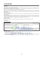
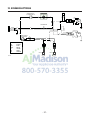
22. WIRING DIAGRAM
LINE
NEUTRAL
GROUND
120 V AC
WHT
M
BRN
BLU
RED
BLK
M
BRN
BLU
RED
BLK
WHT
SPEED
CONTROL
HS
THERMOSTAT
BLU
BLK
BLK
BLU
BLK
WHT
WHT
WHT
WHT
BLK
BLK
YEL
YEL
LAMP
LAMP
SWITCH
L 1
2
FAN
SWITCH
BLU
BLU
BLU
BLU
LAMP
COLOR CODE
HE0092A
BLK BLACK
BLU BLUE
BRN BROWN
RED RED
WHT WHITE
YEL YELLOW

- 16 -
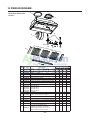
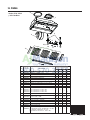
* NOT SHOWN.
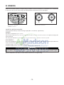
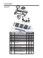
23. SERVICE PARTS
Best CP34, CP35
& CP37 Series
KEY
NO
.
PART NO. DESCRIPTION
QTY. (POWER PACK WIDTH)
30” 36” 42” 48”
1 SV08543 ADAPTER/DAMPER 8” ROUND 1 1 1 -
2 SV08541 ADAPTER 10” ROUND - - - 1
3 SV08097 INTERNAL BLOWER 1 1 1 2
4 SV16569 LAMP SHELL, SOCKET & TRIM ASS ‘Y 2 2 2 2
5 SV03435 HEAT SENTRY™ THERMOSTAT 1 1 1 1
6 SV08338 LIGHT SWITCH 1 1 1 1
7 SV03501 SPEED CONTROL 1 1 1 1
8 SV08578 BLOWER AND LIGHT KNOBS (2 KNOBS) 1 1 1 1
9 SV08548 BLOWER ROCKER SWITCH 1 1 1 1
10 SV17852 FILTER FILLER (PA IR ) - - 1 -
11
SV17870
SV17871
SV17872
SV17873
GREASE RAIL 30”
GREASE RAIL 36”
GREASE RAIL 42”
GREASE RAIL 48”
1
-
-
-
-
1
-
-
-
-
1
-
-
-
-
1
12 SV05869 BEST LOGO 1 1 1 1
13
SV17600
SV17603
BAFFLE FILTER 8.84” X 9.80”
BAFFLE FILTER 11.84” X 9.80”
3
0
1
2
4
0
5
0
14 SV08337 FILTER SPRING (SET OF 6) 1 1 1 1
15 SV07680 BAFFLE FILTER HANDLE WITH SCREWS 3 3 4 5
16 SV05921 SHIELDED HALOGEN LAMPS (120 V, 50 W, GU-10) 2 2 2 2
* SV08542 10” ROUND VERTICAL IN-LINE DAMPER - - - 1
* SV08544 INSTALLATION GUIDE 1 1 1 1
SV08545
PARTS BAG ([2] WIRE CONNECTORS,
[1] WIRE CLAMP, [4] SCREWS NO. 8 X 3/8”,
[9] CHROME PLATED SCREWS NO. 8 X 1/2”,
[10] MECHANICAL SCREWS NO. 8-32 X 1/4”)
1 1 1 1
HL0110
1
2
3
4
5
6
7
8
9
10
11
14
12
15
13
16

SÉRIES CP34, CP35 ET CP37
CONÇUES POUR USAGE DOMESTIQUE SEULEMENT
INSTALLATEUR : LAISSER CE GUIDE AU PROPRIÉTAIRE.
PROPRIÉTAIRE : DIRECTIVES D’UTILISATION ET D’ENTRETIEN
EN PAGES 28 ET 29.
BEST; Hartford, Wisconsin www.BestRangeHoods.com 800 558-1711
ENREGISTREZ VOTRE PRODUIT EN LIGNE À : www.BestRangeHoods.com/register
Pour obtenir plus d’information, consultez notre site www.BestRangeHoods.com
SV08544 rév. G
HB0078
GUIDE D’INSTALLATION
LIRE ET CONSERVER CES DIRECTIVES
!
!

- 18 -
AVERTISSEMENT
AVERTISSEMENT
AFIN DE RÉDUIRE LES RISQUES D’INCENDIE,
D’ÉLECTROCUTION OU DE BLESSURES CORPORELLES,
SUIVEZ LES DIRECTIVES SUIVANTES :
1. N’utilisez cet appareil que de la façon prévue par le
manufacturier. Si vous avez des questions, contactez
le manufacturier à l’adresse et au numéro de
téléphone indiqués dans la garantie.
2. Avant de réparer ou de nettoyer l’appareil, couper
l’alimentation électrique en verrouillant le panneau de
service afin d’éviter sa remise en marche accidentelle.
Si le panneau de service ne peut être verrouillé, y
fixer un avertissement en évidence, telle qu’une
étiquette de couleur vive.
3. Les travaux d’installation et de raccordement
électrique doivent être effectués par une personne
qualifiée, conformément aux codes et aux standards
de construction, incluant ceux concernant la protection
contre les incendies.
4. Une quantité d’air adéquate est requise afin d’assurer
une bonne combustion et l’évacuation des gaz par la
cheminée dans le cas des équipements alimentés au
gaz afin de prévenir les retours de cheminée.
Conformez-vous aux instructions et aux standards de
sécurité des manufacturiers d’équipement de
chauffage, tel qu’ils sont publiés par la
National Fire
Protection Association
(NFPA) et l’
American Society
for Heating, Refrigeration and Air Conditioning
Engineers
(ASHRAE) ainsi que les responsables des
codes locaux.
5. Lorsque vous coupez ou perforez un mur ou un
plafond, prenez garde de ne pas endommager les fils
électriques ou autre installation qui pourraient y
être dissimulés.
6. Les ventilateurs avec conduits doivent toujours évacuer
l’air à l’extérieur.
7. Ne pas utiliser cet appareil avec une commande de
vitesse à semi-conducteur.
8. Afin de réduire les risques d’incendie, n’utilisez que
des conduits de métal.
9. Cet appareil doit être mis à la terre.
10. Lorsqu’une réglementation est en vigueur et qu’elle
comporte des exigences d’installation et/ou de
certification plus restrictives, lesdites exigences
prévalent sur celles de ce document et l’installateur
entend s’y conformer à ses frais.
AFIN DE RÉDUIRE LES RISQUES DE FEU
DE CUISINIÈRE :
a) Ne jamais laisser les appareils de cuisson sans
surveillance lorsqu’ils sont réglés à feu vif. Les
débordements engendrent de la fumée et des
déversements graisseux pouvant s’enflammer.
Chauffez l’huile lentement, à feu doux ou moyen.
b) Mettez toujours la hotte en marche lorsque vous
cuisinez à feu vif ou que vous cuisinez des mets
flambés (par ex. : crêpes Suzette, cerises jubilé, steak
au poivre flambé).
c) Nettoyez régulièrement la (les) roue(s) du ventilateur.
Ne laissez pas la graisse s’accumuler sur le ventilateur
ou les filtres.
d) Utilisez le bon format de casserole. Servez-vous
toujours de casseroles et d’ustensiles appropriés à la
dimension de la surface chauffante.
AFIN D’ÉVITER TOUT RISQUE DE BLESSURES LORS
D’UN FEU DE CUISINIÈRE, SUIVEZ CES DIRECTIVES* :
1. Étouffez les flammes avec un couvercle hermétique,
une tôle à biscuits ou un plateau métallique et
ensuite, éteindre le brûleur. PRENEZ SOIN
D’ÉVITER LES BRÛLURES. SI LES FLAMMES NE
S’ÉTEIGNENT PAS IMMÉDIATEMENT, ÉVACUEZ
LES LIEUX ET APPELEZ LES POMPIERS.
2. NE PRENEZ JAMAIS UNE CASSEROLE EN
FLAMMES DANS VOS MAINS – Vous pourriez
vous brûler.
3. N’UTILISEZ PAS D’EAU, incluant un linge à vaisselle
ou une serviette mouillée, cela pourrait occasionner
une violente explosion de vapeur.
4. N’utilisez un extincteur QUE DANS LE CAS OÙ :
A. Vous savez qu’il s’agit d’un extincteur de classe
ABC et que vous en connaissez le fonctionnement.
B. L’incendie est petit et limité à l’endroit où il a débuté.
C. Les pompiers ont été avisés.
D. Vous pouvez combattre l’incendie en ayant accès
à une sortie de secours.
*Tirées du
Kitchen Fire Safety Tips
publié par la NFPA.
ATTENTION
1. Pour une utilisation à l’intérieur seulement.
2. Pour usage domestique seulement. Ne pas utiliser pour
évacuer des vapeurs ou des matières dangereuses
ou explosives.
3. Afin d’éviter tout dommage au moteur et de débalancer
ou de rendre bruyante la roue du moteur, garder votre
appareil à l’abri des poussières de gypse et de
construction/rénovation, etc.
4. Le moteur de votre hotte encastrable possède une
protection thermique qui éteindra automatiquement le
moteur s’il devient surchauffé. Le moteur redémarrera
automatiquement une fois refroidi. Si le moteur
continue à arrêter et à redémarrer, faites-le vérifier.
5. La distance minimale entre le bas de votre hotte et la
surface de cuisson ne doit pas être inférieure à 24 po.
Un maximum de 30 po au-dessus de la surface de
cuisson est recommandé pour une meilleure
évacuation des odeurs de cuisson.
6. Deux installateurs sont recommandés lors de l’installation
vu la grande dimension et le poids de cet appareil.
7. Afin de réduire les risques d’incendie, assurez-vous
d’évacuer l’air à l’extérieur – Ne pas évacuer l’air dans
des espaces restreints comme l’intérieur des murs ou
plafond ou dans le grenier, faux plafond ou garage.
8. Cet appareil est équipé d’un thermostat pouvant faire
démarrer le ventilateur automatiquement. Afin de
réduire le risque de blessure, couper le courant à partir
du panneau électrique et le verrouiller ou apposer un
avertissement sur le panneau afin de prévenir que la
hotte soit mise en marche accidentellement.
9. À cause de la grande capacité d’évacuation de cet
appareil, il est recommandé d’ouvrir une fenêtre dans
ou près de la cuisine afin de remplacer l’air évacué.
10. Afin de réduire les risques d’incendie et d’électrocution,
les modèles Best de la série CP34, CP35 et CP37
doivent être installés uniquement avec leurs ventilateurs
intérieurs intégrés. Aucun autre ventilateur ne doit
être utilisé.
11. Veuillez consulter l’autocollant apposé à l’intérieur du
produit pour plus d’information ou autres exigences.
!
!

- 19 -
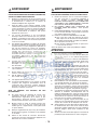
- SYSTÈMES DE HOTTES ENCASTRABLES -
CP34, CP35 ET CP37
MODÈLE 410
(CONDUIT DE 10 PO ROND
— SECTIONS DE 2 PI)
M
ODÈLE 418
(COUDE AJUSTABLE
DE 10 PO ROND)
MODÈLE 437
(C
APUCHON DE TOIT
À HAUT RENDEMENT
)
M
ODÈLE 441
(C
APUCHON MURAL
10 PO ROND)
V
OLET VERTICAL EN LIGNE DE
10 PO ROND (FOURNI AVEC LA HOTTE
ENCASTRABLE À VENTILATEUR DOUBLE)
V
ENTILATEUR DOUBLE (1200 PCM)
(FOURNI AVEC LA HOTTE ENCASTRABLE
DE 48 PO SEULEMENT)
V
ENTILATEUR SIMPLE (600 PCM)
(FOURNI AVEC LES
HOTTES ENCASTRABLES DE
30 PO, 36 PO ET 42 PO SEULEMENT)
A
DAPTATEUR/VOLET 8 PO ROND
(FOURNI AVEC LES HOTTES
ENCASTRABLES À VENTILATEUR SIMPLE)
C
ONDUIT
STANDARD
DE 8 PO ROND)
C
OUDE
AJUSTABLE DE
8 PO ROND
MODÈLE 634 OU 644
(C
APUCHON DE TOIT)
M
ODÈLE 643
(C
APUCHON MURAL
8 PO ROND)
A
DAPTATEUR DE 10 PO ROND
(FOURNI AVEC LA HOTTE
ENCASTRABLE À VENTILATEUR DOUBLE)
HL0122
*LE RÉDUCTEUR DE DÉBIT 300 PCM
EST INTÉGRÉ AU MODÈLE CP34
HOTTE
ENCASTRABLE
CP37
HOTTE
ENCASTRABLE
CP35
HOTTE
ENCASTRABLE
CP34*

Déterminer à quel endroit et comment les conduits seront installés. Un accès
au dessus de la hotte est préférable pour le raccordement des conduits.
Installer des conduits de dimensions appropriées, coude(s) et capuchon de
mur ou de toit selon le type de ventilateur. Pour l’installation de la hotte
encastrable CP34 ou CP35, utiliser des conduits ronds de 8 po et pour
l’installation de la hotte encastrable CP37, utiliser des conduits ronds de 10 po.
Utiliser du ruban adhésif de métal de 2 po pour assurer l’étanchéité des joints.
La distance minimale entre le bas de votre hotte et la surface de cuisson
ne doit pas être inférieure à 24 po. Un maximum de 30 po au-dessus de
la surface de cuisson est recommandé pour une meilleure évacuation des
odeurs de cuisson.
Une distance de plus de 30 po demeure à la discrétion de l’installateur et de l’utilisateur.
Acheminer le câble d’alimentation électrique à 3 conducteurs jusqu’à l’emplacement
de la hotte. Le câble devrait excéder de 4 pi le dessous de la hotte.
2. INSTALLER LES CONDUITS ET LE CÂBLAGE ÉLECTRIQUE
HH0101F
Hotte encastrable
Capuchon de toit
Capuchon
de mur
Conduits ronds de
8 po pour CP34 & CP35
ou de 10 po pour CP37
Adaptateur et volet
8 po rond pour CP34 & CP35
ou adaptateur 10 po rond
pour CP37
De 24 po à 30 po
au-dessus de la
surface de cuisson
Coude rond de 8 po pour CP34 &
CP35 ou de 10 po pour CP37
Volet vertical
10 po rond pour CP37
INSTALLATION TYPE
MODÈLES CP34 ET CP35 (VENTILATEUR SIMPLE)
OU CP37 (VENTILATEUR DOUBLE)
1. PRÉPARER L’INSTALLATION
S’assurer que les articles suivants sont inclus :
- La hotte encastrable
- Accessoires : • Filtres à chicane : CP34 et CP35 : 3 pour les modèles de 30 po et 36 po de largeur, 4 pour le modèle de
42 po de largeur; CP37 : 5 pour ce modèle de 48 po de largeur
• Les poignées des filtres à chicane (fixées avec du ruban adhésif à l’intérieur de la hotte encastrable) :
CP34 et CP35 : 3 pour les modèles de 30 po et 36 po de largeur et 4 pour le modèle de 42 po de largeur;
CP37 : 5 pour ce modèle de 48 po de largeur
• 2 ampoules halogènes avec écran (120 V, 50 W, MR16 avec culot GU10 ou PAR16 avec culot GU10)
• Adaptateur/volet de 8 po rond (fourni avec les hottes encastrables à ventilateur simple)
• Le volet vertical en ligne de 10 po rond (fourni avec la hotte encastrable à ventilateur double)
• L’adaptateur de 10 po rond (fourni avec la hotte encastrable à ventilateur double)
• Le sac de pièces incluant : (1) serre-fils, (2) capuchons de connection , (4) vis n° 8 x 3/8 po,
(9) vis plaquées chrome n° 8 x 1/2 po, (10) vis n° 8-32 x 1/4 po. Jeter les vis excédentaires s’il y a lieu.
Pièces vendues séparément :
- Conduits, coudes, capuchons de mur ou de toit. Consulter la page 19 pour la liste complète des accessoires de ventilation
et les numéros de modèle.
NOTE : Lors de l’installation, protéger la surface de cuisson et le comptoir de cuisine.
3. PRÉPARATION DE L’ARMOIRE POUR HOTTE
AVERTISSEMENT
Toujours suivre les codes et standards en vigueur lors de la contruction de l’armoire pour hotte.
!
Construire l’armoire en fonction du format et du poids total des hottes encastrables CP34, CP35 ou CP37. Consulter le tableau
et l’illustration pour plus de détails.
* Les têtes de rivets sont incluses dans les dimensions A et B.
A
B
C
7/8 po
4½ po
HD0296F
C
L
12 po
3 po
AVERTISSEMENT
Il est recommandé de porter des lunettes et des gants de sécurité lors de l’installation, de l’entretien et de
la réparation de cet appareil.
ARRIÈRE
AVANT
- 20 -
MODÈLE DE HOTTE
ENCASTRABLE
LARGEUR
POIDS
TOTAL
DIMENSIONS DE LA HOTTE
A* B* C
CP34 ET CP35
30 po 33 LB 19
5
⁄16 po 28
7
⁄16 po 4
7
⁄8 po
36 po 37,2 LB 19
5
⁄16 po 34
7
⁄16 po 4
7
⁄8 po
42 po 41,6 LB 19
5
⁄16 po 40
7
⁄16 po 4
7
⁄8 po
CP37 48 po 56,5 LB 22
9
⁄16 po 46
7
⁄16 po 5
7
⁄8 po
!
La page est en cours de chargement...
La page est en cours de chargement...
La page est en cours de chargement...
La page est en cours de chargement...
La page est en cours de chargement...
La page est en cours de chargement...
La page est en cours de chargement...
La page est en cours de chargement...
La page est en cours de chargement...
La page est en cours de chargement...
La page est en cours de chargement...
La page est en cours de chargement...
La page est en cours de chargement...
La page est en cours de chargement...
La page est en cours de chargement...
La page est en cours de chargement...
La page est en cours de chargement...
La page est en cours de chargement...
La page est en cours de chargement...
La page est en cours de chargement...
La page est en cours de chargement...
La page est en cours de chargement...
La page est en cours de chargement...
La page est en cours de chargement...
La page est en cours de chargement...
La page est en cours de chargement...
La page est en cours de chargement...
La page est en cours de chargement...
-
 1
1
-
 2
2
-
 3
3
-
 4
4
-
 5
5
-
 6
6
-
 7
7
-
 8
8
-
 9
9
-
 10
10
-
 11
11
-
 12
12
-
 13
13
-
 14
14
-
 15
15
-
 16
16
-
 17
17
-
 18
18
-
 19
19
-
 20
20
-
 21
21
-
 22
22
-
 23
23
-
 24
24
-
 25
25
-
 26
26
-
 27
27
-
 28
28
-
 29
29
-
 30
30
-
 31
31
-
 32
32
-
 33
33
-
 34
34
-
 35
35
-
 36
36
-
 37
37
-
 38
38
-
 39
39
-
 40
40
-
 41
41
-
 42
42
-
 43
43
-
 44
44
-
 45
45
-
 46
46
-
 47
47
-
 48
48


dans d''autres langues
- English: Best CP34 Installation guide
- español: Best CP34 Guía de instalación