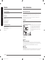
Samsung NV31T4551SS/AA Le manuel du propriétaire
- Catégorie
- Micro-ondes
- Taper
- Le manuel du propriétaire
Ce manuel convient également à

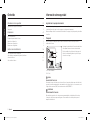
Built-in Oven
Installation manual
NV31T4551**
Install_NV31T4551SS_AA_DG68-01266A-00_EN.indd 1 2020-02-27 PM 3:58:34

2 English
Contents
ContentsContents
Safety informations 2
Related equipment safety 2
Transport 2
Preparation 4
Checklist 4
Prepare to install the oven 4
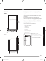
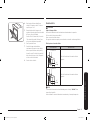
Location requirements 5
Product dimensions 5
Cabinet dimensions 6
Installation instructions 9
Prepare built-in oven 9
Remove and replace oven door(s) 9
Electrical connection 11
Install oven 13
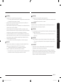
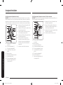
Safety informations
Related equipment safety
Remove all tape and packaging before using the appliance. Dispose of the
packaging after unpacking the appliance. Never allow children to play with
packaging material.
Never modify or alter the construction of the appliance. For example, do not
remove panels, wire covers or screws.
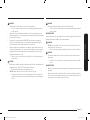
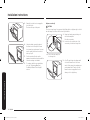
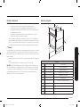
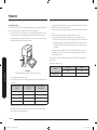
Transport
To avoid damage to the oven vent, use the transport method shown in the picture
below.
A
B
A. Front
B. Pallet
Support the bottom of the oven from either
side when moving it into the installation
location. Leave the unit attached to the
shipping pallet until it is in front of the
cabinet opening and is ready to be lifted
into place.
DANGER
ELECTRICAL SHOCK HAZARD
To avoid risk of electrical shock, personal injury or death; verify your appliance
has been properly grounded in accordance with local codes or in absence of codes,
with the National Electrical Code (NEC). ANSI/NFPA 70-latest edition.
WARNING
MOVING HAZARD
To avoid risk of severe personal injury; this appliance requires two or more people
while handling and moving. Use of appliance moving devices is recommended.
Install_NV31T4551SS_AA_DG68-01266A-00_EN.indd 2 2020-02-27 PM 3:58:35

English 3
Safety informations
WARNING
• The information in this manual should be followed exactly.
• A re or electrical shock may result causing property damage, personal
injury or death.
• Important - Save this installation manual for local electrical inspector's use.
• Proper Installation - Be sure your appliance is properly installed and grounded
by a qualied technician.
• New branch-circuit installations (1996 NEC), mobile homes, recreational
vehicles, or installations where local codes prohibit grounding through the
neutral conductor require 4-wire branch-circuit connection.
• Improper connection of aluminum house wiring to copper leads can result in
an electrical hazard or re. Use only connectors designed for joining copper to
aluminum and follow the manufacturer’s recommended procedure closely.
• Mounting screws must be used.
• Failure to do so can result in the oven falling out of the cabinet causing
serious injury.
CAUTION
• Make sure the cabinets and wall coverings around the oven can withstand the
temperature (up to 194 °F [90 °C]) generated by the oven.
• Discoloration, delamination or melting may occur.
• DO NOT remove spacers on the side walls of the built-in oven.
• These spacers center the oven in the space provided. The oven must be
centered to prevent excess heat buildup that may result in heat damage
or re.
WARNING
• The information in this manual should be followed exactly.
• A re or electrical shock may result causing property damage, personal
injury or death.
IMPORTANT NOTE
Proper installation is the responsibility of the installer and product failure due to
improper installation is NOT covered under warranty.
WARNING
• DO NOT put any weight on the oven door. Never allow anyone to climb, sit,
stand or hang on the oven door.
• The oven could tip and injury might result from food or the oven itself.
WARNING
• The electrical power must be shut off while the electrical connections are
being made.
• Failure to do so can result in severe personal injury, death or electrical
shock.
IMPORTANT NOTE
• Observe all governing codes and ordinances. This appliance must be properly
grounded.
• Keep oven vent ducts unobstructed. The oven vent is located bottom of the
oven. This area could become hot during oven use. Never block this vent or
place plastic or heat-sensitive items in front of it.
Install_NV31T4551SS_AA_DG68-01266A-00_EN.indd 3 2020-02-27 PM 3:58:35

4 English
Preparation
Preparation
Checklist
Use this checklist to verify that you have completed each step of the installation
process. This can help you avoid mistakes.
1. Before installing the oven, be sure to verify the cabinet dimensions are correct
for your unit and the required electrical connections are present.
2. Refer to the installation manual for content regarding Safety, Cabinet
Dimensions, Removing Packaging, Electrical Installation, Testing the
Installation and Customer Service.
3. To lift up the oven, use the handles on the sides of the unit.
4. Move the oven unit into place in front of the cabinet opening, leaving the
bottom packaging on the unit to avoid damaging ooring.
5. Team lift the unit directly into the cabinet cutout taking care not to pinch
ngers or scratch hands or arms. Make sure the electrical conduit reaches to
the connection point properly.
6. Slide the unit all the way into place, making sure to route the electrical conduit
correctly.
7. Fasten the oven unit to the cabinetry opening with screws supplied (using
Phillips screwdriver).
8. Consult the complete installation instructions and follow the remainder of the
procedures listed, including performing an operation test.
9. All product literature and accessories are supplied (may be wrapped or boxed)
with the oven.
10. INSTALLER - Leave the literature pack and the accessories with the customer.
Prepare to install the oven
Phillips Screwdriver 1/8" drill bit and drill
Parts included
2 screws (M4 L25)
Materials needed
Junction Box
3
/4” Conduit Connector
Install_NV31T4551SS_AA_DG68-01266A-00_EN.indd 4 2020-02-27 PM 3:58:35

English 5
Preparation
Location requirements
IMPORTANT: Observe all governing codes and ordinances.
• Cabinet opening dimensions that are shown must be used.
Given dimensions provide minimum clearance with oven.
• Recessed installation area must provide complete enclosure around the
recessed portion of the oven.
• Grounded electrical supply is required. See “Electrical Requirements”
section.
• Electrical supply junction box should be located 3” (7.6 cm) maximum below
the support surface when the oven is installed in a wall cabinet. A 1” (2.5 cm)
minimum diameter hole should have been drilled in the right rear or left
rear corner of the support surface to pass the appliance cable through to the
junction box.
NOTE
For under counter installation, it is recommended that the junction box be located
in the adjacent right or left cabinet. If you are installing the junction box on rear
wall behind oven, it is recommended that the junction box be recessed and located
in the upper Right of the cabinet.
• Oven support surface must be solid, level and ush with bottom of cabinet
cutout.
• Floor must be able to support a single oven weight of 77.8 lb (35.3 kg).
IMPORTANT: To avoid damage to your cabinets, check with your builder or
cabinet supplier to make sure that the materials used will not discolor, delaminate
or sustain other damage. This oven has been designed in accordance with the
requirements of UL and CSA International and complies with the maximum
allowable wood cabinet temperatures of 194 °F (90 °C).
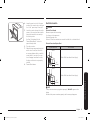
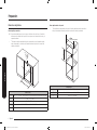
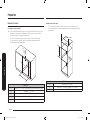
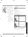
Product dimensions
A
G
E
B
F
C
D-2
D
I
D-1
H
DIMENSION
A 23
1
/2" (596 mm) Overall height
B 22
1
/16" (560 mm) Recessed width
C 22
13
/16" (579 mm) Recessed height
D 24
9
/16" (624 mm) Overall depth (with Handle)
D-1 21
5
/8" (549 mm) Recessed depth
D-2 22
7
/16" (570 mm) Overall depth
E 23
7
/16" (595 mm) Overall width (Door width)
F 61" (1550 mm) Conduit length
G 21
7
/16" (544 mm) Handle width
H 1
15
/16 (49 mm) Handle height
I 41
5
/8" (1057 mm) Overall length (with door open)
Install_NV31T4551SS_AA_DG68-01266A-00_EN.indd 5 2020-02-27 PM 3:58:35

6 English
Preparation
Preparation
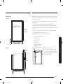
Cabinet dimensions
Single Oven Under counter
01 Gas or Electric cooktops may be installed over this oven. See cooktop
installation instructions for cutout size and necessary clearance.
• ** For single ovens installed under a countertop, the junction box may
be located to the left, or the right of the unit, within reach of the power
conduit connection point.
**
C
D
E
A
B
DIMENSION
A Min.
11
/16"(17.5 mm) - Overlap of Over Side Edges of Cutout
B Min.
11
/16" (17 mm)
C Min. 22
1
/16" (560 mm)
D Min. 23
1
/4" (590 mm) - Max. 23
1
/2" (596 mm)
E Min. 22
1
/4"(565 mm)
Single Oven Wall Mount
• * For wall installations, the junction box may be located above or below
the unit within reach of the power conduit connection point.
A
C
B
*
*
A (Inner side of cabinet)
B
C
DIMENSION
A Min. 22
1
/16" (560 mm)
B Min. 23
1
/4" (590 mm) - Max. 23
1
/2" (596 mm)
C Min. 22
1
/4" (565 mm)
Install_NV31T4551SS_AA_DG68-01266A-00_EN.indd 6 2020-02-27 PM 3:58:35

English 7
Preparation
Flush installation
Top view
Min. 23
7
/8" (605 mm)
13
/16"
(21 mm)
Min. 23
1
/8"
(586 mm)
Min. 22
1
/16" (560 mm)
Side view
Min. 23
1
/8" (586 mm)
13
/16"
(21 mm)
23
1
/2"
(596 mm)
If codes permit and a separate ground wire is used, it is recommended that a
qualied electrical installer determine that the ground path and the wire gauge are
in accordance with local codes.
Check with a qualied electrical installer if you are not sure the oven is properly
grounded.
This oven must be connected to a grounded-metal permanent wiring system.
Be sure that the electrical connection and wire size are adequate and in
conformance with the National Electrical Code, ANSI/NFPA 70-latest edition or CSA
Standards C22.
1-94, Canadian Electrical Code, Part 1 and C22.2 No. O-M91-latest edition, and all
local codes and ordinances.
A copy of the above code standards can be obtained from:
National Fire Protection Association
1 Batterymarch Park
Quincy, MA 02169-7471
CSA International
8501 East Pleasant Valley Road
Cleveland, OH 44131-5575
B
A
Installation under cooktop
To install a cooktop above the oven, check
the installation guide of the cooktop for the
installation space requirement (A, B).
Install_NV31T4551SS_AA_DG68-01266A-00_EN.indd 7 2020-02-27 PM 3:58:36

8 English
Preparation
Preparation
• Flexible conduit from the oven should be connected directly to the junction
box.
• Fuse both sides of the line.
• Do not cut the conduit. The length of conduit provided is for serviceability of
the oven.
• A UL listed or CSA approved conduit connector must be provided.
• If the house has aluminum wiring, follow the procedure below:
1. Connect a section of solid copper wire to the ends of the exible conduit
leads.
2. Connect the aluminum wiring to the added section of copper wire using
special connectors and/or tools designed and UL listed for joining copper
to aluminum.
Follow the electrical connector manufacturer's recommended procedure.
Aluminum/copper connection must conform with local codes and industry
accepted wiring practices.
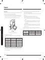
For power requirements for NV31T4551SS model refer to the following table.
Recommended Circuit breaker : 20 Amp
Model
240 VAC 208 VAC
kW kW
NV31T4551SS 3.25 2.45
Electrical Connection
To properly install your oven, you must determine the type of electrical connection
you will be using and follow the instructions provided in this manual.
• Oven must be connected to the proper electrical voltage and frequency as
specied on the model/serial/rating plate. The model/serial/rating plate is
located on the bottom right side of the trim. See the following illustrations.
A
Single Oven
A. Model/serial/rating plate
• A circuit breaker is recommended.
• Use the chart below to determine the minimum recommended dedicated
circuit protection.
KW Rating (240 V) KW Rating (208 V)
Recommended Circuit
Size (Dedicated)
≤4.8 KW ≤4.1 KW 20 Amp
4.9 KW - 7.5 KW 4.3 KW - 6.2 KW 30 Amp
7.3 KW - 9.6 KW 6.3 KW - 8.3 KW 40 Amp
9.7 KW - 12.0 KW 8.4 KW - 10.4 KW 50 Amp
• Connect directly to the circuit breaker box (or fused disconnect) through
exible, armored or nonmetallic sheathed, copper cable (with grounding wire).
See “Electrical Connection” section.
Install_NV31T4551SS_AA_DG68-01266A-00_EN.indd 8 2020-02-27 PM 3:58:36

English 9
Installation instructions
Installation instructions
Prepare built-in oven
WARNING
Excessive Weight Hazard
Use two or more people to move and install an oven.
Failure to do so can result in back or other injury.
1. Decide on the nal location for the oven. Avoid drilling or cutting into house
wiring during installation.
2. To avoid oor damage, set the oven on a cardboard prior to installation. Do
not use handle or any portion of the front frame for lifting.
3. Remove the shipping materials and tape from the oven.
Remember to keep the packing materials that may be needed for installation.
4. Remove the hardware package from inside of the bag containing literature.
5. Remove racks and other parts from inside the oven.
6. Move oven and cardboard close to the oven’s nal location.
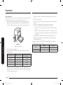
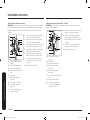
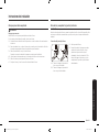
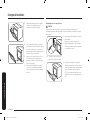
Remove and replace oven door(s)
IMPORTANT: Use two hands to remove oven door.
Prior to removing the oven door, prepare a surface where you will place it. This
surface should be at and covered with a soft blanket, or use the corner posts
from your packaging material.
Remove oven door(s)
A
B
A. Oven door hinge lock in
locked position
B. Oven door hinge lock in
unlocked position
1. Open the oven door.
2. Locate the oven door hinge locks in
both corners of the oven door, and
then rotate the hinge locks toward the
oven door to the unlocked position (see
illustration B). If the door hinge lock
is not rotated fully, the door will not
remove properly.
Install_NV31T4551SS_AA_DG68-01266A-00_EN.indd 9 2020-02-27 PM 3:58:36

10 English
Installation instructions
Installation instructions
3. Partially close the door to engage the
door latch locks.
The door will stop at this point.
4. Using two hands, grasp the edges of
the oven door. Lift and pull the oven
door toward you and remove. You may
need to gently shift door from side to
side as you pull.
5. Set the oven door(s) aside on the
prepared covered work surface with the
oven door resting on its handle.
6. To continue with the oven installation,
go to the “Positioning Oven Feet
for Multiple Cabinet Cutout Heights”
section.
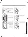
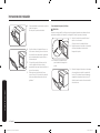
Replace oven door(s)
CAUTION
The door is very heavy. You may need help lifting the door high enough to slide it
into the hinge slots. Do not lift the door by the handle.
A
A. Slot in the oven cavity for
door hinge lock
1. Using two hands, grasp side edges of
door at the midpoint.
Face the oven cavity.
2. Locate the slots on each side of the
oven cavity for the door hinge locks.
3. At a 45° angle, align door hinges with
slots in the lower front of the oven
cavity. Slowly insert door, making sure
you maintain the 45° angle. You will
know the door is engaged in the slot
when you feel a slight drop.
Install_NV31T4551SS_AA_DG68-01266A-00_EN.indd 10 2020-02-27 PM 3:58:36

English 11
Installation instructions
4. Lower the oven door to the fully open
position. If the oven door does not open
to a full 90°, repeat steps 1 through 3.
5. Locate the oven door hinge locks in the
corners of the oven door, and rotate the
hinge locks toward the oven cavity to
the locked position.
See Step 1 (illustration A) in the
“Remove Oven Door(s)” section for
proper locked position.
6. Close the oven door.
7. When the hinges are properly installed
and the door closed, there should be
an even gap between the door and the
control panel. If one side of the oven
door is hanging lower than the other,
the hinge on that side is not properly
installed.
8. Connect Wire Harness.
Electrical connection
WARNING
Electrical Shock Hazard
Disconnect power before servicing.
Use 8 gauge solid copper wire.
Electrically ground oven.
Failure to follow these instructions can result in death, re, or electrical shock.
Electrical Connection Options Chart
If your home has: Go to section:
4-wire
1
/2"
(1.3 cm)
4-Wire Cable from Home Power Supply
3-wire
1
/2"
(1.3 cm)
3-Wire Cable from Home Power Supply
NOTE
If the power connection is plugged in improperly, "bAd LinE" appears on the
display.
Reconnect the power connection properly, and the message disappears.
Install_NV31T4551SS_AA_DG68-01266A-00_EN.indd 11 2020-02-27 PM 3:58:36

12 English
Installation instructions
Installation instructions
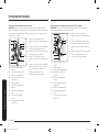
4-Wire Cable from Home Power Supply
IMPORTANT: Use the 4-wire cable from home power supply in the U.S. where local
codes do not allow grounding through neutral, New Branch circuit installations
(1996 NEC), mobile homes and recreational vehicles, new construction and in
Canada.
A
E
B
G
H
I
C
D
F
A. Cable from home power
supply
B. Black wires (normally L1)
C. Red wires (normally L2)
D. 4-wire exible conduit from
oven
E. Junction box
F. White wires (normally
N-neutral)
G. UL listed wire connectors
H. green wires (normally
G-ground)
I. UL listed or CSA approved
conduit connector
1. Connect the 2 black wires (B) together
using a UL listed wire connector.
2. Connect the 2 red wires (C) together
using a UL listed wire connector.
3. Untwist white wire from green (or bare)
ground wire coming from the oven.
4. Connect the 2 white wires (F) together
using a UL listed wire connector.
5. Connect the green (or bare) ground
wire (H) from the oven cable to the
green (or bare) ground wire (in the
junction box) using a UL listed wire
connector.
6. Install junction box cover.
3-Wire Cable from Home Power Supply - U.S. Only
IMPORTANT: Use the 3-wire cable from home power supply where local codes
permit a 3-wire connection.
A
E
B
G
H
I
C
D
F
A. Cable from home power
supply
B. Junction box
C. Black wires (normally L1)
D. White wires (normally
N-neutral)
E. green wires (normally
G-ground)
F. 4-wire exible conduit from
oven
G. Red wires (normally L2)
H. UL listed wire connectors
I. UL listed or CSA approved
conduit connector
1. Connect the 2 black wires (C) together
using a UL listed wire connector.
2. Connect the 2 white wires (D) and
the green (or bare) ground wire (of
the oven cable) using a UL listed wire
connector.
3. Connect the 2 red wires (G) together
using a UL listed wire connector.
4. Install junction box cover.
Install_NV31T4551SS_AA_DG68-01266A-00_EN.indd 12 2020-02-27 PM 3:58:37

English 13
Installation instructions
Install oven
1. Have two or more people lift the oven
using the handles on the sides of the
oven, and then put the oven partially
into the cabinet cutout.
NOTE
Carefully push against front oven frame.
2. Push against the seal area of the front
frame to push the oven into the cabinet
until the back surface of the front frame
touches the front wall of the cabinet.
3. Push oven completely into the cabinet
and center the oven into the cabinet
cutout.
4. Remove the tape from front trims.
• Securely fasten the oven to the
cabinet using the screws provided.
• Insert the screws through hole in
trim aligning with hole in oven
frame. Do not overtighten screws.
Mounting the oven
A
Make sure to leave a gap (A) of at least
1
/4"
(5 mm) between the oven and each side of
the cabinet.
B
Secure at least
1
/8" (3 mm) of gap (B) so that
the door opens and closes smoothly.
Fit the oven into the cabinet and x the
oven rmly on both sides using 2 screws.
Install_NV31T4551SS_AA_DG68-01266A-00_EN.indd 13 2020-02-27 PM 3:58:37

Memo
Install_NV31T4551SS_AA_DG68-01266A-00_EN.indd 14 2020-02-27 PM 3:58:37

Memo
Install_NV31T4551SS_AA_DG68-01266A-00_EN.indd 15 2020-02-27 PM 3:58:37

Please be advised that the Samsung warranty does NOT cover service calls to explain product operation, correct improper installation, or perform normal cleaning or
maintenance.
QUESTIONS OR COMMENTS?
COUNTRY CALL OR VISIT US ONLINE AT
U.S.A
Consumer Electronics
1-800-SAMSUNG (726-7864) www.samsung.com/us/support
CANADA 1-800-SAMSUNG (726-7864)
www.samsung.com/ca/support (English)
www.samsung.com/ca_fr/support (French)
DG68-01266A-00
Scan the QR code* or visit
www.samsung.com/spsn
to view our helpful
How-to Videos and Live Shows
* Requires reader to be installed on your
smartphone
Install_NV31T4551SS_AA_DG68-01266A-00_EN.indd 16 2020-02-27 PM 3:58:38

Horno empotrado
Manual de instalación
NV31T4551**
Install_NV31T4551SS_AA_DG68-01266A-00_MES.indd 1 2020-02-28 PM 1:06:03

2 Español
Contenido
ContenidoContenido
Información sobre seguridad 2
Seguridad de los equipos relacionados 2
Transporte 2
Preparación 4
Lista de vericación 4
Preparación para instalar el horno 4
Requisitos de ubicación 5
Dimensiones del producto 5
Dimensiones del gabinete 6
Instrucciones de instalación 9
Cómo preparar el horno empotrado 9
Cómo retirar y reemplazar la(s) puerta(s) del horno 9
Conexión eléctrica 11
Cómo instalar el horno 13
Información sobre seguridad
Seguridad de los equipos relacionados
Retire toda la cinta y el empaque antes de usar el artefacto. Deseche el empaque luego de quitar
el artefacto. Nunca deje que los niños jueguen con el material de empaque.
Nunca modique o altere la construcción del artefacto. Por ejemplo, no quite paneles, portacables
o tornillos.
Transporte
Utilice el método de transporte que se ilustra a continuación a n de evitar que se dañe la
ventilación del horno.
A
B
A. Parte delantera
B. Palé
Sostenga la parte inferior del horno de ambos lados
al desplazarlo hacia su ubicación de instalación.
Deje la unidad en el palé de envío hasta que esté
frente a la abertura del gabinete y esté listo para
colocarlo en su lugar.
PELIGRO
PELIGRO DE ELECTROCUCIÓN
Para evitar el riesgo de electrocución, lesiones físicas o la muerte, verique que el artefacto esté
conectado a tierra correctamente de conformidad con los códigos locales o, en su ausencia, con el
Código eléctrico nacional (NEC). Versión más reciente de ANSI/NFPA 70.
ADVERTENCIA
PELIGRO DURANTE EL TRASLADO
Este artefacto requiere de dos o más personas para manipularlo o trasladarlo a n de evitar
el riesgo de sufrir lesiones personales graves. Se recomienda el uso de dispositivos para el
transporte del artefacto.
Install_NV31T4551SS_AA_DG68-01266A-00_MES.indd 2 2020-02-28 PM 1:06:03

Español 3
Información sobre seguridad
ADVERTENCIA
• La información de este manual debe seguirse rigurosamente.
• De lo contrario, podrían producirse incendios o descargas eléctricas causantes de daños
a la propiedad, lesiones personales, o la muerte.
• Importante: Conserve este manual de instalación para que pueda ser consultado por el
inspector del servicio eléctrico de su localidad.
• Instalación adecuada - Asegúrese de que su electrodoméstico sea correctamente instalado y
conectado a tierra por un técnico calicado.
• Las nuevas construcciones de circuitos ramales (1996 NEC), casas rodantes, vehículos
recreativos e instalaciones donde los códigos locales prohíben la conexión a tierra mediante
el conductor neutro, requieren conexiones de circuitos ramales de 4 conductores.
• Si el cableado de aluminio de la casa no se conecta adecuadamente a los cables de cobre
podría existir riesgo de electrocución o incendio. Solo utilice conectores diseñados para unir
cobre con aluminio y siga el procedimiento recomendado por el fabricante del conector.
• Se deben utilizar tornillos de montaje.
• De lo contrario, el horno podría caerse del gabinete y ocasionar lesiones graves.
PRECAUCIÓN
• Asegúrese de que los gabinetes y los revestimientos de las paredes alrededor del horno
puedan soportar las temperaturas (hasta 194 °F [90 °C]) que este genera.
• Se podrían producir alteraciones de color, deslaminación o derretimiento.
• NO quite los separadores de las paredes laterales del horno empotrado.
• Estos centran el horno en el espacio provisto. El horno debe estar centrado para evitar
la acumulación excesiva de calor que puede provocar daños o incendios.
ADVERTENCIA
• La información de este manual debe seguirse rigurosamente.
• De lo contrario, podrían producirse incendios o descargas eléctricas causantes de daños
a la propiedad, lesiones personales, o la muerte.
NOTA IMPORTANTE
La instalación adecuada es responsabilidad del instalador y la falla del producto debido a una
instalación inadecuada no está cubierta por la Garantía.
ADVERTENCIA
• NO coloque ningún peso sobre la puerta del horno. Nunca nadie se debe trepar, sentar, parar
o colgar de la puerta del horno.
• El horno podría inclinarse y producir lesiones ya sea por los alimentos calientes o el
mismo horno.
ADVERTENCIA
• Cuando se realizan las conexiones eléctricas, la alimentación eléctrica debe estar cortada.
• De lo contrario, se podrían producir lesiones personales graves, descargas eléctricas o
la muerte.
NOTA IMPORTANTE
• Cumpla todos los códigos y ordenanzas exigidos por las autoridades pertinentes. Este
electrodoméstico debe conectarse a tierra correctamente.
• Mantenga los conductos de ventilación del horno libres de obstrucciones. La abertura de
ventilación del horno está ubicada en la parte inferior del horno. Esta área podría calentarse
durante el uso del horno. Nunca tapone esta abertura de ventilación ni coloque elementos
de plástico o sensibles al calor frente a dicha abertura.
Install_NV31T4551SS_AA_DG68-01266A-00_MES.indd 3 2020-02-28 PM 1:06:04

4 Español
Preparación
Preparación
Lista de vericación
Use esta lista de vericación para comprobar que ha completado todos los pasos del proceso de
instalación. Esto puede ayudarlo a evitar errores.
1. Antes de instalar el horno, asegúrese de vericar que las dimensiones del gabinete sean las
adecuadas para la unidad y que las conexiones eléctricas necesarias estén presentes.
2. Consulte el manual de instalación para ver contenido sobre Seguridad, Dimensiones del
gabinete, Desempaque, Instalación eléctrica, Prueba de la instalación y Servicio al Cliente.
3. Para levantar el horno, use las manijas a los costados de la unidad.
4. Coloque el horno frente a la abertura del gabinete, dejando el empaque inferior en la unidad
para evitar dañar el piso.
5. Levante la unidad con ayuda de otras personas y colóquela directamente en el recorte del
gabinete cuidando de no agarrarse los dedos o rasparse las manos o los brazos. Asegúrese
de que el conducto eléctrico alcance bien el punto de conexión.
6. Deslice la unidad hasta el lugar deseado asegurándose de ir llevando el conducto eléctrico
correctamente.
7. Ajuste el horno a la abertura del gabinete con los tornillos provistos (usando un
destornillador Phillips).
8. Consulte las instrucciones de instalación completas y siga el resto de los procedimientos
indicados, incluida la prueba de funcionamiento.
9. Junto con el horno, se suministran las instrucciones del producto y los accesorios (envueltos
o en caja).
10. INSTALADOR: Las instrucciones y los accesorios deben quedar en manos del cliente.
Preparación para instalar el horno
Destornillador Phillips Taladro y broca de 1/8”
Piezas incluidas
2 tornillos (M4 L25)
Materiales necesarios
Caja de empalmes Conector de conducto de
3
/4”
Install_NV31T4551SS_AA_DG68-01266A-00_MES.indd 4 2020-02-28 PM 1:06:04
La page est en cours de chargement...
La page est en cours de chargement...
La page est en cours de chargement...
La page est en cours de chargement...
La page est en cours de chargement...
La page est en cours de chargement...
La page est en cours de chargement...
La page est en cours de chargement...
La page est en cours de chargement...
La page est en cours de chargement...
La page est en cours de chargement...
La page est en cours de chargement...
La page est en cours de chargement...
La page est en cours de chargement...
La page est en cours de chargement...
La page est en cours de chargement...
La page est en cours de chargement...
La page est en cours de chargement...
La page est en cours de chargement...
La page est en cours de chargement...
La page est en cours de chargement...
La page est en cours de chargement...
La page est en cours de chargement...
La page est en cours de chargement...
La page est en cours de chargement...
La page est en cours de chargement...
La page est en cours de chargement...
La page est en cours de chargement...
-
 1
1
-
 2
2
-
 3
3
-
 4
4
-
 5
5
-
 6
6
-
 7
7
-
 8
8
-
 9
9
-
 10
10
-
 11
11
-
 12
12
-
 13
13
-
 14
14
-
 15
15
-
 16
16
-
 17
17
-
 18
18
-
 19
19
-
 20
20
-
 21
21
-
 22
22
-
 23
23
-
 24
24
-
 25
25
-
 26
26
-
 27
27
-
 28
28
-
 29
29
-
 30
30
-
 31
31
-
 32
32
-
 33
33
-
 34
34
-
 35
35
-
 36
36
-
 37
37
-
 38
38
-
 39
39
-
 40
40
-
 41
41
-
 42
42
-
 43
43
-
 44
44
-
 45
45
-
 46
46
-
 47
47
-
 48
48


Samsung NV31T4551SS/AA Le manuel du propriétaire
- Catégorie
- Micro-ondes
- Taper
- Le manuel du propriétaire
- Ce manuel convient également à