Lincoln Electric Weld-Pak 100 Plus Mode d'emploi
- Catégorie
- Système de soudage
- Taper
- Mode d'emploi

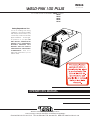
WELD-PAK 100 PLUS
OPERATOR’S MANUAL
IM546
September,1999
Safety Depends on You
Lincoln arc welding and cutting
equipment is designed and built
with safety in mind. However, your
overall safety can be increased by
proper installation ... and thought-
ful operation on your part. DO
NOT INSTALL, OPERATE OR
REPAIR THIS EQUIPMENT
WITHOUT READING THIS
MANUAL AND THE SAFETY
PRECAUTIONS CONTAINED
THROUGHOUT. And, most
importantly, think before you act
and be careful.
For use with machine Code Numbers
10207
and above
For use with machine Code Numbers
10023
For use with machine Code Numbers
10024
For use with machine Code Numbers
10025
For use with machine Code Numbers
10026
For use with machine Code Numbers
10134
WELD-PAK 100
WELD-PAK 100
• Sales and Service through Subsidiaries and Distributors Worldwide •
Cleveland, Ohio 44117-1199 U.S.A. TEL: 216.481.8100 FAX: 216.486.1751 WEB SITE: www.lincolnelectric.com
• World's Leader in Welding and Cutting Products •

i
SAFETY
WELD-PAK 100
PROTECT YOURSELF AND OTHERS FROM POSSIBLE SERIOUS INJURY OR DEATH. KEEP CHILDREN
AWAY. PACEMAKER WEARERS SHOULD CONSULT WITH THEIR DOCTOR BEFORE OPERATING.
Read and understand the following safety highlights. For additional safety information, it is strongly recommended that you pur-
chase a copy of “Safety in Welding & Cutting - ANSI Standard Z49.1” from the American Welding Society, P.O. Box 351040,
Miami, Florida 33135 or CSA Standard W117.2-1974. A Free copy of “Arc Welding Safety” booklet E205 is available from the
Lincoln Electric Company, 22801 St. Clair Avenue, Cleveland, Ohio 44117-1199.
BE SURE THAT ALL INSTALLATION, OPERATION, MAINTENANCE AND REPAIR PROCEDURES ARE PER-
FORMED ONLY BY QUALIFIED INDIVIDUALS.
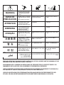
ARC RAYS can burn.
2.a. Use a shield with the proper filter and cover
plates to protect your eyes from sparks and
the rays of the arc when welding or observing
open arc welding. Headshield and filter lens
should conform to ANSI Z87. I standards.
2.b. Use suitable clothing made from durable flame-resistant
material to protect your skin and that of your helpers from
the arc rays.
2.c. Protect other nearby personnel with suitable, non-flammable
screening and/or warn them not to watch the arc nor expose
themselves to the arc rays or to hot spatter or metal.
ELECTRIC SHOCK can
kill.
1.a. The electrode and work (or ground) circuits
are electrically “hot” when the welder is on.
Do not touch these “hot” parts with your bare
skin or wet clothing. Wear dry, hole-free
gloves to insulate hands.
1.b. Insulate yourself from work and ground using dry insulation.
Make certain the insulation is large enough to cover your full
area of physical contact with work and ground.
In addition to the normal safety precautions, if welding
must be performed under electrically hazardous
conditions (in damp locations or while wearing wet
clothing; on metal structures such as floors, gratings or
scaffolds; when in cramped positions such as sitting,
kneeling or Iying, if there is a high risk of unavoidable or
accidental contact with the workpiece or ground) use
the following equipment:
• Semiautomatic DC Constant Voltage (Wire) Welder.
• DC Manual (Stick) Welder.
• AC Welder with Reduced Voltage Control.
1.c. In semiautomatic or automatic wire welding, the electrode,
electrode reel, welding head, nozzle or semiautomatic
welding gun are also electrically “hot”.
1.d. Always be sure the work cable makes a good electrical
connection with the metal being welded. The connection
should be as close as possible to the area being welded.
1.e. Ground the work or metal to be welded to a good electrical
(earth) ground.
1.f.
Maintain the electrode holder, work clamp, welding cable and
welding machine in good, safe operating condition. Replace
damaged insulation.
1.g. Never dip the electrode in water for cooling.
1.h. Never simultaneously touch electrically “hot” parts of
electrode holders connected to two welders because voltage
between the two can be the total of the open circuit voltage
of both welders.
1.i. When working above floor level, use a safety belt to protect
yourself from a fall should you get a shock.
1.j. Also see Items 4.c. and 6.
WARNING
ARC WELDING can be hazardous.
FUMES AND GASES
can be dangerous.
3.a. Welding may produce fumes and gases
hazardous to health. Avoid breathing these
fumes and gases.When welding, keep
your head out of the fume. Use enough
ventilation and/or exhaust at the arc to keep
fumes and gases away from the breathing zone. When
welding with electrodes which require special
ventilation such as stainless or hard facing (see
instructions on container or MSDS) or on lead or
cadmium plated steel and other metals or coatings
which produce highly toxic fumes, keep exposure as
low as possible and below Threshold Limit Values (TLV)
using local exhaust or mechanical ventilation. In
confined spaces or in some circumstances, outdoors, a
respirator may be required. Additional precautions are
also required when welding on galvanized steel.
3.b.
Do not weld in locations near chlorinated hydrocarbon
vapors
coming from degreasing, cleaning or spraying operations.
The heat and rays of the arc can react with solvent vapors
to
form phosgene, a highly toxic gas, and other irritating
products.
3.c. Shielding gases used for arc welding can displace air and
cause injury or death. Always use enough ventilation,
especially in confined areas, to insure breathing air is safe.
3.d. Read and understand the manufacturerʼs instructions for this
equipment and the consumables to be used, including the
material safety data sheet (MSDS) and follow your
employerʼs safety practices. MSDS forms are available from
your welding distributor or from the manufacturer.
3.e. Also see item 7b.
Apr. ʻ93

ii
WELD-PAK 100
SAFETY
FOR ELECTRICALLY
powered equipment.
6.a. Turn off input power using the disconnect
switch at the fuse box before working on
the equipment.
6.b. Install equipment in accordance with the U.S. National
Electrical Code, all local codes and the manufacturerʼs
recommendations.
6.c. Ground the equipment in accordance with the U.S. National
Electrical Code and the manufacturerʼs recommendations.
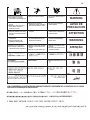
CYLINDER may explode
if damaged.
5.a. Use only compressed gas cylinders
containing the correct shielding gas for the
process used and properly operating
regulators designed for the gas and
pressure used. All hoses, fittings, etc. should be suitable for
the application and maintained in good condition.
5.b. Always keep cylinders in an upright position securely
chained to an undercarriage or fixed support.
5.c. Cylinders should be located:
• Away from areas where they may be struck or subjected to
physical damage.
• A safe distance from arc welding or cutting operations and
any other source of heat, sparks, or flame.
5.d. Never allow the electrode, electrode holder or any other
electrically “hot” parts to touch a cylinder.
5.e. Keep your head and face away from the cylinder valve outlet
when opening the cylinder valve.
5.f. Valve protection caps should always be in place and hand
tight except when the cylinder is in use or connected for
use.
5.g. Read and follow the instructions on compressed gas
cylinders, associated equipment, and CGA publication P-l,
“Precautions for Safe Handling of Compressed Gases in
Cylinders,” available from the Compressed Gas Association
1235 Jefferson Davis Highway, Arlington, VA 22202.
Mar. ʻ93
WELDING SPARKS can
cause fire or explosion.
4.a.
Remove fire hazards from the welding area.
If this is not possible, cover them to prevent
the welding sparks from starting a fire.
Remember that welding sparks and hot
materials from welding can easily go through small cracks
and openings to adjacent areas. Avoid welding near
hydraulic lines. Have a fire extinguisher readily available.
4.b. Where compressed gases are to be used at the job site,
special precautions should be used to prevent hazardous
situations. Refer to “Safety in Welding and Cutting” (ANSI
Standard Z49.1) and the operating information for the
equipment being used.
4.c. When not welding, make certain no part of the electrode
circuit is touching the work or ground. Accidental contact
can cause overheating and create a fire hazard.
4.d. Do not heat, cut or weld tanks, drums or containers until the
proper steps have been taken to insure that such procedures
will not cause flammable or toxic vapors from substances
inside. They can cause an explosion even
though
they have
been “cleaned”. For information, purchase “Recommended
Safe Practices for the
Preparation
for Welding and Cutting of
Containers and Piping That Have Held Hazardous
Substances”, AWS F4.1 from the American Welding Society
(see address above).
4.e. Vent hollow castings or containers before heating, cutting or
welding. They may explode.
4.f.
Sparks and spatter are thrown from the welding arc. Wear oil
free protective garments such as leather gloves, heavy shirt,
cuffless trousers, high shoes and a cap over your hair. Wear
ear plugs when welding out of position or in confined places.
Always wear safety glasses with side shields when in a
welding area.
4.g. Connect the work cable to the work as close to the welding
area as practical. Work cables connected to the building
framework or other locations away from the welding area
increase the possibility of the welding current passing
through lifting chains, crane cables or other alternate cir-
cuits. This can create fire hazards or overheat lifting chains
or cables until they fail.
4.h. Also see item 7c.

iii
SAFETY
WELD-PAK 100
Mar. ʻ93
ELECTRIC AND MAGNETIC
FIELDS
may be dangerous
8.a. Electric current flowing through any conductor causes
localized Electric and Magnetic Fields (EMF). Welding
current creates EMF fields around welding cables and
welding machines
8.b. EMF fields may interfere with some pacemakers, and
welders having a pacemaker should consult their physician
before welding.
8.c. Exposure to EMF fields in welding may have other health
effects which are now not known.
8d. All welders should use the following procedures in order to
minimize exposure to EMF fields from the welding circuit:
8.d.1.
Route the electrode and work cables together - Secure
them with tape when possible.
8.d.2. Never coil the electrode lead around your body.
8.d.3. Do not place your body between the electrode and
work cables. If the electrode cable is on your right
side, the work cable should also be on your right side.
8.d.4. Connect the work cable to the workpiece as close as
possible to the area being welded.
8.d.5. Do not work next to welding power source.
FOR ENGINE
powered equipment.
7.a. Turn the engine off before troubleshooting and maintenance
work unless the maintenance work requires it to be running.
____________________________________________________
7.b. Operate engines in open, well-ventilated
areas or vent the engine exhaust fumes
outdoors.
____________________________________________________
7.c. Do not add the fuel near an open flame
welding arc or when the engine is running.
Stop the engine and allow it to cool before
refueling to prevent spilled fuel from
vaporizing on contact with hot engine parts
and igniting. Do not spill fuel when filling
tank. If fuel is spilled, wipe it up and do not
start engine until fumes have been
eliminated.
____________________________________________________
7.d. Keep all equipment safety guards, covers
and devices in position and in good repair.
Keep hands, hair, clothing and tools away
from V-belts, gears, fans and all other
moving parts when starting, operating or
repairing equipment.
____________________________________________________
7.e. In some cases it may be necessary to remove safety
guards to perform required maintenance. Remove
guards only when necessary and replace them when the
maintenance requiring their removal is complete.
Always use the greatest care when working near moving
parts.
7.f. Do not put your hands near the engine fan. Do not
attempt to override the governor or idler by pushing on
the throttle control rods while the engine is running.
7.g. To prevent accidentally starting gasoline engines while
turning the engine or welding generator during maintenance
work, disconnect the spark plug wires, distributor cap or
magneto wire as appropriate.
___________________________________________________
7.h. To avoid scalding, do not remove the
radiator pressure cap when the engine is
hot.

iv
SAFETY
WELD-PAK 100
PRÉCAUTIONS DE SÛRETÉ
Pour votre propre protection lire et observer toutes les instruc-
tions et les précautions de sûreté specifiques qui parraissent
dans ce manuel aussi bien que les précautions de sûreté
générales suivantes:
Sûreté Pour Soudage A LʼArc
1. Protegez-vous contre la secousse électrique:
a. Les circuits à lʼélectrode et à la piéce sont sous tension
quand la machine à souder est en marche. Eviter toujours
tout contact entre les parties sous tension et la peau nue
ou les vétements mouillés. Porter des gants secs et sans
trous pour isoler les mains.
b. Faire trés attention de bien sʼisoler de la masse quand on
soude dans des endroits humides, ou sur un plancher
metallique ou des grilles metalliques, principalement dans
les positions assis ou couché pour lesquelles une
grande partie du corps peut être en contact avec la
masse.
c. Maintenir le porte-électrode, la pince de masse, le câble
de soudage et la machine à souder en bon et sûr état
defonctionnement.
d.Ne jamais plonger le porte-électrode dans lʼeau pour le
refroidir.
e. Ne jamais toucher simultanément les parties sous tension
des porte-électrodes connectés à deux machines à soud-
er parce que la tension entre les deux pinces peut être le
total de la tension à vide des deux machines.
f. Si on utilise la machine à souder comme une source de
courant pour soudage semi-automatique, ces precautions
pour le porte-électrode sʼapplicuent aussi au pistolet de
soudage.
2. Dans le cas de travail au dessus du niveau du sol, se pro-
téger contre les chutes dans le cas ou on recoit un choc. Ne
jamais enrouler le câble-électrode autour de nʼimporte quelle
partie du corps.
3. Un coup dʼarc peut être plus sévère quʼun coup de soliel,
donc:
a. Utiliser un bon masque avec un verre filtrant approprié
ainsi quʼun verre blanc afin de se protéger les yeux du
rayonnement de lʼarc et des projections quand on soude
ou quand on regarde lʼarc.
b. Porter des vêtements convenables afin de protéger la
peau de soudeur et des aides contre le rayonnement de
lʻarc.
c. Protéger lʼautre personnel travaillant à proximité au
soudage à lʼaide dʼécrans appropriés et non-inflamma-
bles.
4. Des gouttes de laitier en fusion sont émises de lʼarc de
soudage. Se protéger avec des vêtements de protection
libres de lʼhuile, tels que les gants en cuir, chemise épaisse,
pantalons sans revers, et chaussures montantes.
5. Toujours porter des lunettes de sécurité dans la zone de
soudage. Utiliser des lunettes avec écrans lateraux dans les
zones où lʼon pique le laitier.
6. Eloigner les matériaux inflammables ou les recouvrir afin de
prévenir tout risque dʼincendie dû aux étincelles.
7. Quand on ne soude pas, poser la pince à une endroit isolé de
la masse. Un court-circuit accidental peut provoquer un
échauffement et un risque dʼincendie.
8. Sʼassurer que la masse est connectée le plus prés possible
de la zone de travail quʼil est pratique de le faire. Si on place
la masse sur la charpente de la construction ou dʼautres
endroits éloignés de la zone de travail, on augmente le risque
de voir passer le courant de soudage par les chaines de lev-
age, câbles de grue, ou autres circuits. Cela peut provoquer
des risques dʼincendie ou dʼechauffement des chaines et des
câbles jusquʼà ce quʼils se rompent.
9. Assurer une ventilation suffisante dans la zone de soudage.
Ceci est particuliérement important pour le soudage de tôles
galvanisées plombées, ou cadmiées ou tout autre métal qui
produit des fumeés toxiques.
10. Ne pas souder en présence de vapeurs de chlore provenant
dʼopérations de dégraissage, nettoyage ou pistolage. La
chaleur ou les rayons de lʼarc peuvent réagir avec les
vapeurs du solvant pour produire du phosgéne (gas forte-
ment toxique) ou autres produits irritants.
11. Pour obtenir de plus amples renseignements sur la sûreté,
voir le code “Code for safety in welding and cutting” CSA
Standard W 117.2-1974.
PRÉCAUTIONS DE SÛRETÉ POUR
LES MACHINES À SOUDER À
TRANSFORMATEUR ET À
REDRESSEUR
1. Relier à la terre le chassis du poste conformement au code
de lʼélectricité et aux recommendations du fabricant. Le dis-
positif de montage ou la piece à souder doit être branché à
une bonne mise à la terre.
2. Autant que possible, Iʼinstallation et lʼentretien du poste
seront effectués par un électricien qualifié.
3. Avant de faires des travaux à lʼinterieur de poste, la
debrancher à lʼinterrupteur à la boite de fusibles.
4. Garder tous les couvercles et dispositifs de sûreté à leur
place.
Mar. ʻ93

v
WELD-PAK 100
Thank You
for selecting a QUALITY product by Lincoln Electric.
We want you to take pride in operating this Lincoln
Electric Company product ••• as much pride as we
have in bringing this product to you!
Read this Operatorʼs Manual completely before attempting to use this equipment. Save this manual and keep it
handy for quick reference. Pay particular attention to the safety instructions we have provided for your protection.
The level of seriousness to be applied to each is explained below:
WARNING
This statement appears where the information must be followed exactly to avoid serious personal injury or
loss of life.
This statement appears where the information must be followed to avoid minor personal injury or damage to
this equipment.
CAUTION
Please Examine Carton and Equipment For Damage Immediately
When this equipment is shipped, title passes to the purchaser upon receipt by the carrier. Consequently, Claims
for material damaged in shipment must be made by the purchaser against the transportation company at the time
the shipment is received.
Please record your equipment identification information below for future reference. This information can be found
on your machine nameplate.
Code Number _____________________________________
Serial Number _____________________________________
Model Name _____________________________________
Date of Purchase __________________________________
Whenever you request replacement parts for or information on this equipment always supply the information you
have recorded above.

vi
FEB 95 WELD-PAK 100
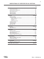
MASTER TABLE OF CONTENTS FOR ALL SECTIONS
Page
Installation .......................................................................................................Section A
Technical Specifications ........................................................................................A-1
Identify and Locate Components...........................................................................A-2
Select Suitable Location ........................................................................................A-3
Output Connections...............................................................................................A-3
Input Connections..................................................................................................A-6
Code Requirements ..............................................................................................A-6
Operation .........................................................................................................Section B
Safety Precautions ................................................................................................B-1
General Description...............................................................................................B-2
Design Features and Advantages...................................................................B-2
Welding Capability ..........................................................................................B-2
Limitations .......................................................................................................B-2
Controls and Settings......................................................................................B-2
Welding Operations ...............................................................................................B-3
Overload Protection...............................................................................................B-6
Learning to Weld....................................................................................................B-7
Application Chart .................................................................................................B-18
Accessories.....................................................................................................Section C
Accessories ...........................................................................................................C-1
Replacement Parts................................................................................................C-1
Maintenance ....................................................................................................Section D
Safety Precautions ................................................................................................D-1
Items Requiring No Maintenance ..........................................................................D-1
Routine Maintenance.............................................................................................D-1
Gun and Cable Maintenance.................................................................................D-2
Component Replacement Procedures ..................................................................D-2
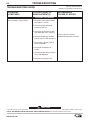
Troubleshooting..............................................................................................Section E
Safety Precautions.................................................................................................E-1
How to Use Troubleshooting Guide.......................................................................E-1
Troubleshooting Guide ..........................................................................................E-2
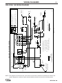
Wiring Diagrams..............................................................................................Section F
WELD-PAK 100 Wiring Diagram ...........................................................................F-1
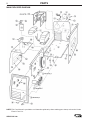
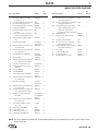
WELD-PAK 100 Parts Manual.........................................................................Appendix

WELD-PAK 100
vii

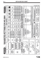
Fuse or
Output Mode Input Voltage Breaker Size Input Amps Power Cord Extension Cord
RATED 115V/60Hz 20 Amp 20 15 Amp, 125V,
Three Conductor
Three Prong Plug
#14 AWG
(NEMA Type 5-15P)
(2.1 mm
2
) or Larger
Up to 25 Ft. (7.6 mm)
CSA 115V/60Hz 15 Amp 12 15 Amp, 125V, Three Conductor
Three Prong Plug #12 AWG
(NEMA Type 5-15P) (3.3 mm
2
) or Larger
Up to 50 Ft. (15.2 mm)
A-1
INSTALLATION
WELD-PAK 100
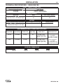
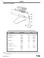
TECHNICAL SPECIFICATIONS – WELD-PAK 100
INPUT – SINGLE PHASE ONLY
RATED OUTPUT
OUTPUT
RECOMMENDED INPUT CABLE AND FUSE SIZES
Height Width Depth Weight
12.0 in 9.75 in 16.5 in 47 Ibs
305 mm 248 mm 419 mm 21.4 kg
PHYSICAL DIMENSIONS
Standard Voltage/Frequency Input Current
115V/60Hz 20 Amps - Rated Output
115V/60Hz 15 Amps - CSA Rated output
Duty Cycle Amps Volts at Rated Amperes
20% Duty Cycle 88 18
20% Duty Cycle – CSA Rated Output 62 20
Welding Current Range (Continuous) Maximum Open Circuit Voltage Auxiliary Power
Rated DC Output: 0 - 88 amps 32 N/A
CSA Rated DC Output: 0 - 62 amps

A-2
INSTALLATION
WELD-PAK 100 JAN96
Read entire installation section before starting
installation.
SAFETY PRECAUTIONS
IDENTIFY AND LOCATE
COMPONENTS
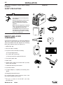
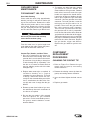
If you have not already done so, unpack the Weld-Pak
100 from its carton and remove all packing material
around the WELD-PAK 100. Remove the following
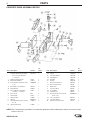
loose items from the carton (see Figure A.1):
1. WELD-PAK 100
2. Gun and cable assembly
(1)
3. Literature and miscellaneous including:
a) This operating manual
b) 10 extra .035" contact tips
c) Hex key wrench for removal of drive roll.
4. 10 ft (3,0 m) work cable.
5. Work clamp.
6. Sample 10 lb. spool of Innershield .035" (0,9 mm)
NR-211-MP electrode.
7. Handshield with filter plate and lens.
8. Instructional video.
9. 8” Spool Adapter (2” Spindle) for mounting 10 lb.
Spools
10. Chipping hammer/wire brush
For available options and accessories refer to the
Accessories Section of this manual.
(1)
The gun is ready to feed 0.035" (0,9 mm)
Innershield wire.
ELECTRIC SHOCK can kill.
• Only qualified personnel should perform
this installation.
• Only personnel that have read and under-
stood the WELD-PAK 100 Operating
Manual should install and operate this
equipment.
• Machine must be plugged into a receptacle
which is grounded per any national, local
or other applicable electrical codes.
• The WELD-PAK 100 power switch is to be
in the OFF (“O”) position when installing
work cable and gun and when connecting
power cord to input power.
WARNING
FIGURE A.1
WELD-PAK 100
WELD
-
P
AK 10
0
1
2
3
4
5
6
7
8
10
10
9

A-3
INSTALLATION
WELD-PAK 100
SELECT SUITABLE LOCATION
Locate the welder in a dry location where there is free
circulation of clean air into the louvers in the back and
out the front of the unit. A location that minimizes the
amount of smoke and dirt drawn into the rear louvers
reduces the chance of dirt accumulation that can block
air passages and cause overheating.
STACKING
WELD-PAK 100ʼs cannot be stacked.
TILTING
Each machine must be placed on a secure, level sur-
face, either directly or on a recommended undercar-
riage. The machine may topple over if this procedure
is not followed.
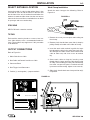
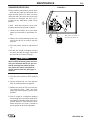
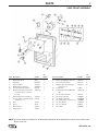
OUTPUT CONNECTIONS
Refer to Figure A.2.
1. Work Cable Access Hole.
2. Gun Cable and Control Lead Access Hole.
3. Connector Block.
4. Gun Trigger Lead Connectors.
5. Positive (+) and negative (–) output terminals.
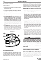
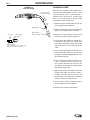
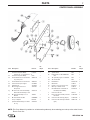
Work Clamp Installation
Attach the work clamp per the following: Refer to
Figure A-3.
FIGURE A.3
WELD-PAK 100
WELD-PAK 100
4
5
8
3 6
7
1
2
+
-
1. Remove the screw, pressure plate and backing nut
from clamp.
2. Remove plastic handle from same side of clamp by
pulling steadily on handle until it slides off clamp.
3. Insert the work cable terminal lug with the larger
hole through the hole in the end of the plastic han-
dle. Slide plastic handle several inches further onto
cable to allow easy and clear access to terminal
lug.
4. Secure work cable to clamp by inserting screw
through hole in clamp, attaching cable lug on inside
of clamp, and installing pressure plate and backing
nut. make sure pressure plate is installed such that
it prevents nut from turning. tighten screw securely.
5. Slide plastic handle back onto clamp and into origi-
nal position.
FIGURE A.2
SCREW
SCREW
PLASTIC HANDLE
PLASTIC HANDLE
WORK CABLE
WORK CABLE
BACKING PLATE & NUT
BACKING PLATE & NUT

1
2
4
3
A-4
INSTALLATION
WELD-PAK 100
Work Cable Installation
Refer to Figure A.2.
1. Open the wire feed section door on the right side of
the WELD-PAK 100.
2. Pass the end of the work cable that has the termi-
nal lug with the smaller hole through the Work
Cable Access Hole (1) in the case front.
3. Route the cable under and around the back of the
Wire Feed Gearbox (6).
4. For Innershield Only: Refer to Figure A.2. As
delivered, the WELD-PAK 100 is connected for
negative electrode polarity. This is the appropriate
configuration for the Innershield process. To com-
plete installation, use the provided wing nut to con-
nect the work cableʼs terminal lug to the positive (+)
output terminal (5) located above the Wire Feed
Gearbox (6). Make sure that both wing nuts are
tight.
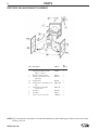
5. For GMAW Only: Refer to Figure A.4. To wire for
positive polarity (required for the MIG process),
connect the short cable attached to the connector
block (1) to the positive (+) output terminal (4) and
the work cable (3) to the negative (–) terminal (2).
FIGURE A.4
appropriate size. Additionally, the .023 – .030" (0.6 –
0.8 mm) gun liner included in the K610-1 MIG
Conversion Kit must be installed. Refer to the MAIN-
TENANCE section for contact tip installation details.
Connecting Gun Cable to the WELD-PAK
100
1. Refer to Figure A.2. Unplug the machine or turn
power switch to the OFF “O” position.
2. Pass the insulated terminals of the gun trigger con-
trol leads, one at a time, through the Gun Cable
and Control Lead Access Slot (2) in the case front.
The leads are to be routed under the Wire Feed
Gearbox (6) and through the Cable Hanger (7) on
the inner panel.
3. Insert the connector on the gun conductor cable
through the Gun Cable Access Hole (2) in the
WELD-PAK 100 case front. Make sure the connec-
tor is all the way in the brass connector block.
Unscrew thumbscrew on the connector block a few
turns if gun connector will not insert fully. Rotate
the connector so control leads are on the under-
side and tighten the Thumbscrew (8) in the con-
nector block.
4. Connect the gun trigger control lead terminals to
the two insulated 1/4" (6,4 mm) tab terminal con-
nector bushings located above the “Gun Trigger
Connection” decal in the wire feed section (4).
Either lead can go to either connector. Form the
leads so that they are as close as possible to the
inside panel.
If the gun trigger switch being used is other than
that supplied with the WELD-PAK 100, the switch
must be a normally open, momentary switch. The
terminals of the switch must be insulated from the
welding circuit. Malfunction of the WELD-PAK 100
may result if this switch shorts to the WELD-PAK
100 welding output circuit or is common to any
electrical circuit other than the WELD-PAK 100
trigger circuit.
GAS CONNECTION (OPTIONAL)
When using the GMAW process, a K610-1 MIG con-
version kit and a cylinder of carbon dioxide (CO
2
)or
argon-carbon dioxide mixed shielding gas must be
obtained. For more information about the K610-1 MIG
Conversion Kit for use with the WELD-PAK 100, refer
to the ACCESSORIES section.
CAUTION
GUN INSTALLATION
As shipped from the factory, the WELD-PAK 100 gun
is ready to feed 0.035” (0,9 mm) wire. If .023" – .025"
(0,6 mm) or .030" (0.8 mm) wire is to be used for the
GMAW (MIG) process, change the contact tip to the

A-5
INSTALLATION
WELD-PAK 100
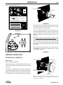
2. With the cylinder securely installed, remove the
cylinder cap. Stand to one side away from the out-
let and open the cylinder valve very slightly for an
instant. This blows away any dust or dirt which may
have accumulated in the valve outlet.
BE SURE TO KEEP YOUR FACE AWAY FROM THE
VALVE OUTLET WHEN “CRACKING” THE VALVE.
Never stand directly in front of or behind the flow
regulator when opening the cylinder valve. Always
stand to one side.
3. Attach the flow regulator to the cylinder valve and
tighten the union nut securely with a wrench..
NOTE: If connecting to 100% CO
2
cylinder, insert
regulator adapter (provided with MIG Conversion
Kit for the WELD-PAK 100) between regulator and
cylinder valve. If adapter is equipped with a plastic
washer, be sure it is seated for connection to the
CO
2
cylinder.
4. Refer to Figure A.6. Attach one end of inlet gas
hose to the outlet fitting of the flow regulator and
tighten the union nut securely with a wrench.
Connect the other end to the WELD-PAK 100 Gas
Solenoid Inlet Fitting (5/8-18 female threads — for
CGA — 032 fitting). Make certain the gas hose is
not kinked or twisted.
CYLINDER may explode if dam-
aged. Keep cylinder upright and
chained to support
• Keep cylinder away from areas
where it may be damaged.
• Never lift welder with cylinder
attached.
• Never allow welding electrode to
touch cylinder.
• Keep cylinder away from welding
or other live electrical circuits.
BUILDUP OF SHIELDING GAS may
harm health or kill.
• Shut off shielding gas supply
when not in use.
• SEE AMERICAN NATIONAL
STANDARD Z-49.1, “SAFETY IN
WELDING AND CUTTING” PUB-
LISHED BY THE AMERICAN
WELDING SOCIETY.
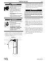
1. Chain the cylinder to a wall or other stationary sup-
port to prevent the cylinder from falling over.
Insulate the cylinder from the work circuit and earth
ground. Refer to Figure A.5.
FIGURE A.5
WARNING
WARNING
Cylinder Valve
Gas Hose
Flow Regulator
WARNING

A-6
INSTALLATION
WELD-PAK 100
INPUT CONNECTIONS
FIGURE A.6
Refer to Figure A.6.
The WELD-PAK 100 has a power input cable located
on the rear of the machine.
CODE REQUIREMENTS FOR INPUT
CONNECTIONS
This welding machine must be connected to
power source in accordance with applicable elec-
trical codes.
The United States National Electrical Code (Article
630-B, 1990 Edition) provides standards for
amperage handling capability of supply conduc-
tors based on duty cycle of the welding source.
If there is any question about the installation
meeting applicable electrical code requirements,
consult a qualified electrician.
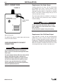
Requirements For Rated Output
A power cord with a 15 amp, 125 volt, three prong
plug (NEMA Type 5-15P) is factory installed on the
WELD-PAK 100. Connect this plug to a mating
grounded receptacle which is connected to a 20 amp
branch circuit with a nominal voltage rating of 115 to
125 volts, 60 Hertz, AC only.
The rated output with this installation is 88 amps, 18
Volts, 20% duty cycle (2 minutes of every 10 minutes
used for welding).
Do not connect the WELD-PAK 100 to an input
power supply with a rated voltage that is greater
than 125 volts.
Do not remove the power cord ground prong.
Requirements For CSA Rated Output
A line cord with a 15 amp, 125 volt, three-prong plug
(NEMA Type 5-15P) is factory installed. Connect this
plug to a mating grounded receptacle which is con-
nected to a 15 amp branch circuit with a nominal volt-
age rating of 115 volts to 125 volts, 60 hertz, AC only.
With this installation, the WELD-PAK 100 can be used
at an output of 62 amps, 20 volts, 20% duty cycle.
WARNING
CAUTION
POWER INPUT
CABLE
OPTIONAL GAS
SOLENOID INLET FITTING

WELD-PAK 100
B-1
OPERATION
Read entire operation section before
operating the WELD-PAK 100.
ELECTRIC SHOCK can kill.
• Do not touch electrically live
parts or electrode with skin or
wet clothing. Insulate yourself
from work and ground.
• Always wear dry insulating
gloves.
FUMES AND GASES can be
dangerous.
• Keep your head out of fumes.
• Use ventilation or exhaust to
remove fumes from breathing
zone.
WELDING SPARKS can
cause fire or explosion.
• Keep flammable material away.
• Do not weld on closed contain-
ers.
ARC RAYS can burn eyes
and skin.
• Wear eye, ear and body protec-
tion.
Observe all safety information throughout
this manual.
WARNING

WELD-PAK 100 JAN96
B-2
OPERATION
GENERAL DESCRIPTION
The WELD-PAK 100 is a compact lightweight DC wire
feeder/power source. It has been designed for work-
shop, hobby, and light maintenance. It is capable of
general purpose welding with self-shielded flux-cored
(Innershield
®
) wire. When combined with the optional
K610-1 MIG Conversion Kit, the WELD-PAK 100 is
suitable for GMAW (MIG) welding applications.
The WELD-PAK 100 is ideally suited for individuals
having access to 115 volt AC input power, and wanti-
ng the ease of use, quality and dependability of both
gas metal arc welding or GMAW (also known as MIG
welding) and the Innershield electrode process (self
shielded flux cored or FCAW). The WELD-PAK 100 is
a rugged and reliable machine that has been
designed for dependable service and long life.
RECOMMENDED PROCESSES
The WELD-PAK 100 can be used for welding mild
steel using the self shielded, Innershield electrode
process (FCAW) or it can be used for the GMAW, sin-
gle pass, process which requires a supply of shielding
gas and the K610-1 MIG Conversion Kit. The WELD-
PAK 100 is configured for use with the FCAW process
as delivered from the factory.
OPERATIONAL FEATURES AND
CONTROLS
The WELD-PAK 100 has the following controls as
standard: Power ON/OFF Switch, Voltage Control,
Wire Speed Control, Trigger Switch, and a Circuit
Breaker.
DESIGN FEATURES AND
ADVANTAGES
● Operates on 115 volt input — no special wiring
required.
● “Cold electrode” until gun trigger is pressed for an
added measure of safety.
● Overload protection — incorporates both a thermo-
stat and a circuit breaker.
● Quality wire drive with electronic overload protec-
tion.
● “Quick Release” idle roll pressure arm is easily
adjusted.
● Reversible, dual groove drive roll. Drive roll will
feed .023 – .025” (0.6 mm) and .030" and .035"
(0.8 mm and 0.9 mm) diameter wire.
● No external shielding gas is required when used
with Lincoln Innershield .035” (0,9 mm) NR
®
-211-
MP electrode.
● Accommodates 4” (100 mm) diameter spool of
wire. Will accommodate 8” (200 mm) diameter with
optional spindle.
WELDING CAPABILITY
The WELD-PAK 100 is rated at 88 amps, 18 volts, at
20% duty cycle on a ten minute basis. CSA rated out-
put at 62 amps at 20 volts at 20% duty cycle. It is
capable of higher output currents at lower duty cycles.
LIMITATIONS
Arc Gouging cannot be performed with the WELD-
PAK 100. The WELD-PAK 100 is not recommended
for pipe thawing or TIG welding.
CONTROLS AND SETTINGS
Refer to Figure B.1a.
1. Power ON/OFF Switch —
When the power is on the
fan motor will run and air will
be exhausted out the louvers
in the front of the machine.
The welding output and wire
feeder remain off until the
gun trigger is pressed.
2. Wire Speed Control —
Controls the wire feed speed
from 50 – 300 in /min (1.3 –
7.6 m/min). The control can
be preset on the dial to the
setting specified on the
WELD-PAK 100 Application
Chart located on the inside
of the wire feed section door.
3. Voltage Control — A 4-posi-
tion tap selector switch gives
full range adjustment of
power source output voltage.
Do not switch while welding.
Refer to Figure B-1b.
4. Circuit Breaker – Protects machine from damage if
maximum output is exceeded. Button will extend
OFF
ON
ARC VOLTS
WIRE SPEED

WELD-PAK 100
B-3
OPERATION
out when tripped (Manual reset).
FIGURE B.1a
FIGURE B.1b
WELDING OPERATIONS
SEQUENCE OF OPERATION
Wire Loading
Refer to Figure B.2 AND B3.
The machine power switch should be turned to the
OFF (“O”) position before working inside the wire feed
enclosure.
The machine is shipped from the factory ready to feed
4” (100 mm) diameter spools. A 4" (100 mm) diameter
spool is mounted directly on the 5/8" (16 mm) diame-
ter spindle that has a built-in adjustable friction brake
FIGURE B.2
to prevent overrun of the spool and excess slack in the
wire. The wing nut at the end of the shaft is used to
adjust the tension on the wire spool.
To use 8" (200 mm) diameter spools, the 2" (51 mm)
diameter M15445 spindle must be used. Remove the
spacer and wing nut at the end of the shaft. Insert
spindle as shown in figure B.3. Reattach spacer and
wing nut.
Make certain the start end of the wire, which may pro-
trude through the side of the spool, does not contact
any metallic case parts.
FIGURE B.3
WELD-PAK 100
WELD-PAK 100
3
2
1
4
Wire Spool must be pushed all the way on the spindle so that the
spindleʼs tab will hold it in place. The Wire Spool will rotate clock-
wise when wire is dereeled.
8” Wire Spool
Wire Spool Spindle
Be sure that this stud engages
the hole in the wire spool.
To Wire Drive
Note:When loading and removing the 8” Spools make
sure that the wing nut (inside the wire spool spindle
hub) is turned 90° from the wire spool spindle locking
tab. If the wing nut is positioned in line with the locking
tab, the tab cannot be depressed to load or unload the
wire spool.
LOCKING TAB
Wire Spindle Shaft
4" Wire Spool
Wing Nut
and Spacer

WELD-PAK 100
B-4
OPERATION
Friction Brake Adjustment
1. With wire spool installed, check free movement
and coast of the spool.
2. To tighten the brake turn the wing nut clockwise in
1/4 turn increments until coasting stops.
3. To loosen the brake turn the wing nut counter-
clockwise in 1/4 turn increments until the wire spool
moves freely without coasting.
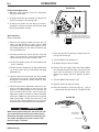
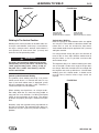
Wire Threading
Refer to Figure B-4
1. Release the Spring Loaded Pressure Arm (1)
rotate the Idle Roll Arm (2) away from. the Wire
Feed Drive Roll (3). Ensure that the groove size in
the feeding position on the drive roll matches the
wire size being used.
2. Carefully detach the end of the wire from the
spool. To prevent the spool from unwinding,
maintain tension on the wire until after step 5.
3. Cut the bent portion of wire off and straighten the
first 4” (100 mm).
4. Thread the wire through the In-going guide tube
(4), over the drive roll (3), and into the out-going
guide tube (5).
5. Close the idle roll arm and latch the spring loaded
pressure arm (2) in place . Rotate the spool coun-
terclockwise if required in order to take up extra
slack in the wire.
6. The idle roll pressure adjustment wing nut is nor-
mally set for mid-position on the pressure arm
threads. If feeding problems occur because the
wire is flattened excessively, turn the pressure
adjustment counter-clockwise to reduce distortion
of the wire. Slightly less pressure may be required
when using 0.023 – 0.025” (0,6 mm) wire. If the
drive roll slips while feeding wire, the pressure
should be increased until the wire feeds properly.
When inching the welding wire, the drive rolls, the
gun connector block and the gun contact tip are
electrically energized relative to work and ground
and remain energized for several seconds after
the gun trigger is released.
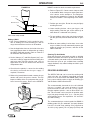
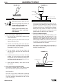
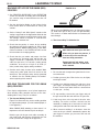
7. Refer to Figure B.5. Remove gas nozzle and con-
tact tip from end of gun.
8. Turn the WELD-PAK 100 ON (“I”).
9. Straighten the gun cable assembly.
10. Depress the gun trigger switch and feed welding
wire through the gun and cable. (Point gun away
from yourself and others while feeding wire.)
Release gun trigger after wire appears at end of
gun.
11. Turn the WELD-PAK 100 OFF (“O”).
12. Replace contact tip and gas nozzle.
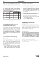
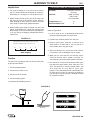
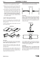
13. Refer to Figure B-6. Cut the wire off 1/4” – 3/8” (6
– 10 mm) from the end of the tip. The WELD-PAK
WARNING
FIGURE B.4
The Wire Drive Feed Roll can
accommodate two wire sizes by
flipping the wire drive feed roll
over.
FIGURE B.5
Gun Handle
Gas Diffuser/
Contact Tip
Gas Nozzle
1
2
3
4
5

WELD-PAK 100
B-5
OPERATION
100 is now ready to weld.
Making A Weld
1. See “Process Guidelines” in this section for selec-
tion of welding wire and shielding gas and for
range of metal thicknesses that can be welded.
2. See the Application chart on the inside of the wire
feed compartment door for information on setting
the WELD-PAK 100 controls. Refer to Table B.1
for aluminum and stainless wire.
3. Set the Voltage (“V”) and Wire Speed (“oloʼ”) con-
trols to the settings suggested for the welding wire
and base metal thickness being used, refer to
Applications chart on the inside of the wire drive
compartment door.
4. Check that the polarity is correct for the welding
wire being used and that the gas supply, if
required, is turned on.
5. When using Innershield electrode, remove the gas
nozzle and install the gasless nozzle. This will
improve visibility of the arc and protect the gas dif-
fuser from weld spatter. Refer to the MAINTE-
FIGURE B.6 NANCE section for details on nozzle replacement.
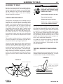
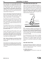
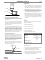
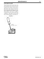
6. Refer to Figure B.7. Connect work clamp to metal
to be welded. Work clamp must make good elec-
trical contact to the workpiece. The workpiece
must also be grounded as stated in “Arc Welding
Safety Precautions” in the beginning of this manu-
al.
7. Position gun over joint. End of wire may be lightly
touching the work.
8. Lower welding helmet, close gun trigger, and
begin welding. Hold the gun so the contact tip to
work distance is about 3/8 inch (10 mm).
9. To stop welding, release the gun trigger and then
pull the gun away from the work after the arc goes
out.
10. When no more welding is to be done, close valve
on gas cylinder (if used), momentarily operate gun
trigger to release gas pressure, and turn off the
WELD-PAK 100.
Cleaning Tip And Nozzle
Clean the contact tip and nozzle to avoid arc bridging
between the nozzle and contact tip which can result in
a shorted nozzle, poor welds and an overheated gun.
Hint: Anti-stick spray or gel, available from a welding
supply distributor, may reduce buildup and aid in spat-
ter removal.
PROCESS GUIDELINES
The WELD-PAK 100 can be used for welding mild
steel using the self shielded, Innershield electrode
process or it can be used for the GMAW (MIG), single
pass, process which requires a supply of shielding gas
and the K610-1 MIG Conversion Kit.
The recommended electrode for the self-shielded
process is 0.035” (0,9 mm) diameter Lincoln
Innershield NR-211-MP on 10 Ib (4,5 kg) spools.
Requires optional spindle – refer to Accessories sec-
tion. This electrode can be used for all position weld-
ing of 20 gauge through 5/16” (1,0 – 8,0 mm) thick
steel [multiple passes are required for 1/4” and 5/16”
(6,0 and 8,0 mm)].
The recommended gas and electrode for GMAW is
welding grade CO
2
gas and 0.025” (0 6 mm) diameter
Lincoln L-56 mild-steel welding wire [supplied on
12-1/2 Ib (6 kg) spools]. For 14 gauge (2,0 mm) and
3/8" – 1/2" Electrical Stickout
Contact Tip
Wire Electrode
FIGURE B.7
WELD-PAK 100
WORKPIECE
GUN CABLE
ARC
WORK CLAMP

WELD-PAK 100
B-6
OPERATION
thinner, CO
2
gas is recommended because it gives
equal or better performance than a blended gas at a
lower cost. A mixed gas consisting of 75 to 80% Argon
and 20 to 25% CO
2
is recommended for welding on
heavier gauge [12 gauge (2,5 mm) for example] steel.
The WELD-PAK 100 is suitable for .035" aluminum
wire and .030" stainless wire. Refer to Table B.1 for
recommended procedure settings.
TABLE B.1
CHANGING MACHINE OVER TO
FEED OTHER WIRE SIZES
The WELD-PAK 100 is shipped from the factory ready
to feed 0.035” (0,9 mm) diameter wire. To operate the
WELD-PAK 100 with other sizes of wire, it is neces-
sary to change the contact tip and change the drive
roll over to other sizes. Refer to Changing the Contact
Tip and Changing the Drive Roll, in the MAINTE-
NANCE section, for specific information on these pro-
cedures.
WELDING WITH GMAW (MIG)
Shielding Gas
When using the GMAW process, obtain and install the
K610-1 MIG Conversion Kit and a cylinder of carbon
dioxide (CO
2
) or argon-carbon dioxide mixed shielding
gas. Refer to the ACCESSORIES section for more
information about installing the K610-1 Kit for use with
the WELD-PAK 100.
1. For CO
2
, open the cylinder very slowly. For argon-
mixed gas, open cylinder valve slowly a fraction of
a turn. When the cylinder pressure gauge pointer
stops moving, open the valve fully.
2. If using a regulator with an adjustable flow meter,
close the gun trigger and adjust the flow to give 15
– 20 cubic ft per hour (CFH) (7 – 10 I/min) [use 20
– 25 CFH (10 – 12 I/min) when welding out of
position or in a drafty location for CO
2
]. For argon
mixed gas, trigger to release gas pressure, and
turn off the adjust the flow to give 25 – 30 CFH
(12–14I/min).
3. Keep the cylinder valve closed, except when using
the WELD-PAK 100. When finished welding:
a) Close the cylinder valve to stop gas flow.
b) Depress the gun trigger briefly to release the
pressure in the gas hose.
c) Turn off the WELD-PAK 100.
OVERLOAD PROTECTION
Output Overload
The WELD-PAK 100 is equipped with a circuit breaker
and a thermostat which protects the machine from
damage if maximum output is exceeded. The circuit
breaker button will extend out when tripped. The cir-
cuit breaker must be manually reset.
Thermal Protection
The WELD-PAK 100 has a rated output duty cycle of
20%. If the duty cycle is exceeded, a thermal protector
will shut off the output until the machine cools to a rea-
sonable operating temperature. This is an automatic
function of the WELD-PAK 100 and does not require
user intervention. The fan continues to run during
cooling.
Electronic Wire Drive Motor Protection
The WELD-PAK 100 has built-in protection for wire
drive motor overload.
Shielding
Voltage/Wire Speed
Process Welding Wire Gas 16 ga 14 ga 12 ga 10 ga
MIG DC+ .035 Dia 100% Argon B-5 D-7 D-9 D-9
4043 Aluminum
Wire
MIG DC+ .035 Dia 100% Argon B-5 C-7 D-9 D-10
5356 Aluminum
Wire
MIG DC+ .030 Dia 98% Argon/ A-3 C-6 D-7.5 D-7.5
308L Stainless 2% Oxygen
Steel Wire
La page est en cours de chargement...
La page est en cours de chargement...
La page est en cours de chargement...
La page est en cours de chargement...
La page est en cours de chargement...
La page est en cours de chargement...
La page est en cours de chargement...
La page est en cours de chargement...
La page est en cours de chargement...
La page est en cours de chargement...
La page est en cours de chargement...
La page est en cours de chargement...
La page est en cours de chargement...
La page est en cours de chargement...
La page est en cours de chargement...
La page est en cours de chargement...
La page est en cours de chargement...
La page est en cours de chargement...
La page est en cours de chargement...
La page est en cours de chargement...
La page est en cours de chargement...
La page est en cours de chargement...
La page est en cours de chargement...
La page est en cours de chargement...
La page est en cours de chargement...
La page est en cours de chargement...
La page est en cours de chargement...
La page est en cours de chargement...
La page est en cours de chargement...
La page est en cours de chargement...
La page est en cours de chargement...
La page est en cours de chargement...
La page est en cours de chargement...
La page est en cours de chargement...
La page est en cours de chargement...
La page est en cours de chargement...
La page est en cours de chargement...
La page est en cours de chargement...
La page est en cours de chargement...
La page est en cours de chargement...
-
 1
1
-
 2
2
-
 3
3
-
 4
4
-
 5
5
-
 6
6
-
 7
7
-
 8
8
-
 9
9
-
 10
10
-
 11
11
-
 12
12
-
 13
13
-
 14
14
-
 15
15
-
 16
16
-
 17
17
-
 18
18
-
 19
19
-
 20
20
-
 21
21
-
 22
22
-
 23
23
-
 24
24
-
 25
25
-
 26
26
-
 27
27
-
 28
28
-
 29
29
-
 30
30
-
 31
31
-
 32
32
-
 33
33
-
 34
34
-
 35
35
-
 36
36
-
 37
37
-
 38
38
-
 39
39
-
 40
40
-
 41
41
-
 42
42
-
 43
43
-
 44
44
-
 45
45
-
 46
46
-
 47
47
-
 48
48
-
 49
49
-
 50
50
-
 51
51
-
 52
52
-
 53
53
-
 54
54
-
 55
55
-
 56
56
-
 57
57
-
 58
58
-
 59
59
-
 60
60


Lincoln Electric Weld-Pak 100 Plus Mode d'emploi
- Catégorie
- Système de soudage
- Taper
- Mode d'emploi
dans d''autres langues
Documents connexes
-
Lincoln Electric 215 Manuel utilisateur
-
Lincoln Electric Pro-MIG 180 Mode d'emploi
-
Lincoln Electric VANTAGE 500 Mode d'emploi
-
-
-
-
Lincoln Electric POWER MIG 216 Mode d'emploi
-
Lincoln Electric Classic 300D Manuel utilisateur
-
-
