
Wattstopper
®
Emergency Lighting Control Unit
Installation Instructions • Instructions d’Installation • Instrucciones de Instalación
No: 23996 – 05/19 rev. 2
Catalog Number • Numéro de Catalogue • Número de Catálogo: ELCU-200
Country of Origin: Made in China • Pays d’origine: Fabriqué en Chine • País de origen: Hecho en China
ELCU-200-U is BAA and TAA compliant (Product produced in the U.S.)
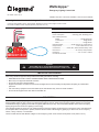
09860r1
Cir.#_______
Emergency
Power
Remote
Activation
Normal
Power
Push to Test
R8.5
mm
Circle
CUT-OUT
EMERGENCY CIRCUIT
SPECIFICATIONS
Voltages ............................................................ 120/277VAC 50/60Hz
Power Consumption ...................... 230mW @ 120V, 360mW @ 277V
Max Load Requirements
Ballast .......................................................... 20A @120/277VAC
Incandescent ....................................................... 10A @120VAC
Motor .................................................................. 1HP @120VAC
Remote Activation ......................24VDC sourced, dry contact closure
Integral Control ..........................................Push-to-Test button on unit
Conformance ................. UL924, NEC, OSHA, NFPA life safety codes
Environment ...........................................32º-122ºF (0º-50ºC) Ambient
Dimensions ................................................... 3.0”L x 2.16”H x 1.6W”W
UL 2043 Plenum Rated
DESCRIPTION
The ELCU-200 Emergency Lighting Control Unit allows lighting control devices for normal lighting and to also control emergency
lighting installed within the area. The ELCU is designed for lighting control in areas where emergency lighting fixtures are connected
on dedicated emergency lighting circuits that are typically ON 24 hours per day. The ELCU allows ON/OFF control of the emergency
lighting along with the normal room lighting to save energy.
The intended operation of the ELCU is to guarantee that the emergency lighting is ON whenever normal power to the controlled circuit
is interrupted. While normal power is present, the ELCU allows control of the emergency lighting by a device such as an occupancy
sensor, a relay, a dimmer, or a wall switch.
The ELCU-200 will work with different voltages on the emergency power circuit and the normal power circuit (120V or 277V).
IMPORTANT SAFEGUARDS
When using electrical equipment always follow basic safety precautions, including:
• READ AND FOLLOW ALL SAFETY INSTRUCTIONS–SAVE THESE INSTRUCTIONS.
• Mount only to an approved electrical enclosure.
• Do not use near gas or electric heaters.
• Equipment should be mounted in locations and at heights where it will not readily be subjected to tampering by unauthorized
personnel.
• Use of accessory equipment not recommended by the manufacturer may cause an unsafe condition.
• Do not use this equipment for other than the intended use.
WARNING
TURN POWER OFF AT CIRCUIT BREAKER BEFORE INSTALLING.
ONLY QUALIFIED ELECTRICIANS SHOULD INSTALL THE ELCU-200.

2
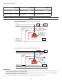
Wiring Reference Table:
Emergency
Power Out
(Red)
Standard wiring for switched control of emergency lighting
along with normal lighting
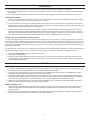
Alternate wiring for dimmer bypass on an emergency circui
t
09860r1
Cir.#_______
Emergency
Power
Remote
Activation
Normal
Power
Push to Test
R8.5
mm
Circle
CUT-OUT
EMERGENCY CIRCUIT
Normal Line
Normal Neutral
Cut Jumper Loop
to use with
normally closed
- Test switch
- Fire alarm panel
- Security panel
- Other
Emergency
Power In
(Black)
Emergency
Neutral
(Gray)
Emergency
Power Out
(Red)
Normal
Neutral
(White)
Normal
Switch Sens
e
(Red)
Normal
Power Sense
(Black)
Control
Device
Normal
Lighting
Emergency Line
“Always On”
Emergency Neutral
Emergency
Lighting
09860r1
Cir.#_______
Emergency
Power
Remote
Activation
Normal
Power
Push to Test
R8.5
mm
Circle
CUT-OUT
EMERGENCY CIRCUIT
Normal Line
Normal Neutral
Cut Jumper Loop
to use with
normally closed
- Test switch
- Fire alarm panel
- Security panel
- Other
Emergency
Power In
(Black)
Emergency
Neutral
(Gray)
Normal
Neutral
(White)
Dimmer
Normal
Lighting
Emergency Neutral
Emergency
Lighting
Dimmer
Cap
Emergency Line
“Always On”
Normal Switch Sense (Red)
Normal
Power Sense
(Black)
AWG/Color AWG/Color AWG/Color
Emergency Power In 12 Black Emergency Neutral 18 Gray Emergency Power Out 12 Red
Normal Power Sense 18 Black Normal Neutral 18 White Normal Switch Sense 18 Red
WIRING
Wiring Notes
1. You can connect as many NC contacts (including LMTS-100) in series on the jumper loop wire as you want to a single ELCU. You
cannot connect the NC devices in any other manner.
2. At no time can more than 5 ELCU devices can be controlled together by commoning their Test Loop wires to a Normally Closed
Test Switch (LMTS) and/or other NC contact closure.
3. If connecting ELCUs together via their test loop wires, you must maintain the polarity of their wires.

3
INSTALLATION
• ELCU units should be installed in accordance with state, local and national electrical codes and requirements.
• ELCU units are designed to attach to a junction box or electrical enclosures that are fitted with a 7/8” diameter opening (standard
1/2”knockout).
• ELCU units operate with power provided by two sources. Place a warning label on each enclosure that contains an ELCU unit.
Installation Procedure
1. Remove the locking nut from the ELCU unit and insert the unit’s threaded nipple through the appropriate knockout. Tighten
the locking nut so that the unit is secured to the j-box or enclosure.
2. Connect the ELCU to the emergency lighting for the area controlled. Connect the Emergency wiring leads on the ELCU in
series with the emergency lighting load as shown in the wiring diagram. Connect the neutral for the emergency circuit to the
Emergency Neutral lead as shown in the wiring diagram.
3. Connect the ELCU to the control device for the area controlled. Connect the ELCU’s Normal wiring leads to the normal
lighting circuit as shown in the wiring diagram. Note that the Normal Power Sense connection should be made to the line
side of the control device that serves the same area as the emergency lighting. This ensures that the emergency lighting in
the controlled area turns ON during a localized power failure such as a tripped branch circuit breaker.
Installing the Optional Remote Activation Device
The ELCU provides leads for connection of a remote device that can force the unit into the emergency ON mode. The leads are
in the form of a factory installed jumper loop (blue wire) on the ELCU. When the loop is complete, it disables this function. Do not
cut this jumper unless remote activation is desired. The device that provides remote activation of the emergency ON mode must
provide a normally closed, maintained contact dry contact closure. The remote device opens the contacts to force the ELCU into
the emergency ON mode.
The most common remote device is a test switch that is installed in an accessible location. Alternately, the blue wire leads can be
used to allow another system such as a fire alarm or security system to force the ELCU into the emergency ON mode.
1. Perform initial testing before cutting the blue wire jumper loop.
2. Cut the blue wire jumper loop.
3. Connect the two resulting leads on the ELCU to the single pole contacts on the remote device or test switch. The device must
provide normally closed, maintained contact dry contact closure. The remote device opens the circuit in order to force the ELCU
into the emergency ON mode.
TESTING
Initial testing should be done with the blue wire jumper loop intact to limit the possibility of a remote device affecting the testing.
1. Turn ON the circuit breaker in the emergency panel for the controlled circuit. The green LED on the ELCU should glow. With only
the emergency circuit ON (normal power OFF) the emergency lighting should be ON.
2. Temporarily disconnect and cap the wire connected to the Normal Switch Sense lead on the ELCU. This disables the normal
control function and allows definitive testing of the fail-to-ON functionality.
3. Turn ON the circuit breaker in the normal panel for the controlled circuit. The amber LED glows indicating that normal power is
present and that emergency lighting is not required. The emergency lighting should turn OFF. Confirm the automatic emergency
ON functionality by turning OFF the normal circuit breaker. The emergency lighting should immediately turn ON.
4. With the normal circuit breaker OFF, re-connect the wire to the Switch In lead. Turn ON the normal circuit breaker. The control
device now controls both the normal and emergency lighting together.
Remote Activation Test
1. Cut the blue wire jumper and connect the leads to the single pole contacts on the remote device or test switch. With the remote
device in normal mode (contacts closed) the red LED on the ELCU is ON and the unit operates just as it did with the factory
jumper loop intact.
2. When the remote device activates (for example, push the test switch) the red LED extinguishes, indicating a true test condition.
The ELCU is forced into the emergency ON mode and the green LED is ON.

800.879.8585
www.legrand.us/Wattstopper
No. 23996 – 05/19 rev. 2
© Copyright 2019 Legrand All Rights Reserved.
© Copyright 2019 Tous droits réservés Legrand.
© Copyright 2019 Legrand Todos los derechos reservados.
Wattstopper warranties its products to be free
of defects in materials and workmanship for a
period of five (5) years. There are no obligations
or liabilities on the part of Wattstopper for
consequential damages arising out of, or in
connection with, the use or performance of this
product or other indirect damages with respect
to loss of property, revenue or profit, or cost of
removal, installation or reinstallation.
Wattstopper garantit que ses produits sont
exempts de défauts de matériaux et de fabrication
pour une période de cinq (5) ans. Wattstopper
ne peut être tenu responsable de tout dommage
consécutif causé par ou lié à l’utilisation ou
à la performance de ce produit ou tout autre
dommage indirect lié à la perte de propriété, de
revenus, ou de profits, ou aux coûts d’enlèvement,
d’installation ou de réinstallation.
Wattstopper garantiza que sus productos
están libres de defectos en materiales y mano
de obra por un período de cinco (5) años. No
existen obligaciones ni responsabilidades por
parte de Wattstopper por daños consecuentes
que se deriven o estén relacionados con el
uso o el rendimiento de este producto u otros
daños indirectos con respecto a la pérdida
de propiedad, renta o ganancias, o al costo
de extracción, instalación o reinstalación.
WARRANTY INFORMATION INFORMATIONS RELATIVES À LA GARANTIE INFORMACIÓN DE LA GARANTÍA
-
 1
1
-
 2
2
-
 3
3
-
 4
4


wattstopper Wattstopper ELCU-200 Guide d'installation
- Taper
- Guide d'installation
- Ce manuel convient également à
dans d''autres langues
Documents connexes
Autres documents
-
Legrand LMRC-212 DLM Dual Relay w/0-10V Dimming Room Controller Quick Start Guide d'installation
-
-
-
Legrand LMRC-111/112 Dimming Room Controllers Guide d'installation