IMPORTANT INSTRUCTIONS -
OPERATING MANUAL
SAVE THESE INSTRUCTIONS
www.airkinglimited.com
6727902 Rev. D 10-16 1 of 12
Exhaust Fan with Light
Models: DL4S, DL4SG,
DL4SH, DL4SGH
READ AND SAVE THESE INSTRUCTIONS
READ CAREFULLY BEFORE ATTEMPTING TO ASSEMBLE, INSTALL, OPERATE OR MAINTAIN
THE PRODUCT DESCRIBED. PROTECT YOURSELF AND OTHERS BY OBSERVING ALL SAFETY
INFORMATION. FAILURE TO COMPLY WITH INSTRUCTIONS COULD RESULT IN PERSONAL
INJURY AND/OR PROPERTY DAMAGE!
RETAIN INSTRUCTIONS FOR FUTURE REFERENCE.
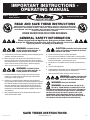
GENERAL SAFETY INFORMATION
When using electrical appliances, basic precautions should
always be followed to reduce the risk of fire, electric shock and
injury to person, including the following:
WARNING: TO REDUCE THE RISK
OF FIRE, ELECTRIC SHOCK AND INJURY TO
PERSON, OBSERVE THE FOLLOWING:
a) Use this unit only in the manner intended by the manufacturer.If you have
questions, contact the manufacturer.
b) Before servicing or cleaning the unit, switch power off at service
panel and lock the service disconnecting means to prevent power
from being switched on accidentally. When the service disconnecting
means cannot be locked, securely fasten a prominent warning
device, such as a tag, to the service panel.
WARNING: TO REDUCE THE RISK
OF FIRE, ELECTRIC SHOCK AND INJURY TO
PERSON, OBSERVE THE FOLLOWING:
a) Installation work and electrical wiring must be done by qualified
person(s) in accordance with all applicable codes and standards,
including fire-related construction.
b) Sufficient air is needed for proper combustion and exhausting of
gases through the flue (chimney) of fuel burning equipment to prevent
back drafting. Follow the heating equipment manufacturer’s guideline
and safety standards such as those published by the National Fire
Protection Association (NFPA) and the American Society for Heating,
Refrigeration, and Air Conditioning Engineers (ASHRAE), and the local
code authorities.
c) When cutting or drilling into wall or ceiling, do not damage electrical
wiring and other hidden utilities.
CAUTION: FOR GENERAL VENTILATING USE ONLY.
DO NOT USE TO EXHAUST HAZARDOUS OR EXPLOSIVE
MATERIALS AND VAPORS.
d) Ducted fans must always be vented to the outdoors.
e) If this unit is to be installed over a tub or shower, it must be marked
as appropriate for the application and be connected to a GFCI (Ground
Fault Circuit Interrupter) – protected branch circuit.
f) Do not install in a ceiling with thermal insulation value greater than
R40.
g) This unit must be grounded.
h) To avoid motor bearing damage and noisy and/or unbalanced impellers,
keep drywall spray, construction dust, etc. off power unit.
i) Read all instructions before installing or using exhaust fan.
WARNING: TO REDUCE THE RISK OF FIRE,
ELECTRIC SHOCK, DO NOT USE THIS FAN WITH
ANY SOLID-STATE SPEED CONTROL DEVICE.
WARNING: DO NOT USE IN KITCHENS.
WARNING: THE DUCTING FROM THIS FAN TO THE
OUTSIDE OF THE BUILDING HAS A STRONG EFFECT ON THE
AIR FLOW, NOISE AND ENERGY USE OF THE FAN. USE THE SHORTEST,
STRAIGHTEST DUCT ROUTING POSSIBLE FOR BEST PERFORMANCE,
AND AVOID INSTALLING THE FAN WITH SMALLER DUCTS THAN
RECOMMENDED. INSULATION AROUND THE DUCTS CAN REDUCE
ENERGY LOSS AND INHIBIT MOLD GROWTH. FANS INSTALLED WITH
EXISTING DUCTS MAY NOT ACHIEVE THEIR RATED AIRFLOW.

INSTALLATION INSTRUCTIONS
CAUTION: MAKE SURE POWER IS SWITCHED OFF AT
SERVICE PANEL BEFORE STARTING INSTALLATION.
SECTION 1
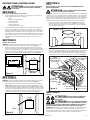
Preparing the Exhaust Fan
1. Unpack fan from the carton and confirm that all pieces are present. In addition to the
exhaust fan you should have:
1 - Grill
1 - Damper Assembly (attached)
4 - Mounting Rails
1 - Mounting Flange
1 - LED Lamp
1 - Instruction/Safety Sheet
2. Choose the location for your fan. To ensure the best air and sound performance, it is
recommended that the length of ducting and the number of elbows be kept to a minimum,
the radius of each elbow be as large as possible for the installation, and that insulated
hard ducting be used. Larger duct sizes will reduce noise and airflow restrictions. This
fan will require at least 10” of clearance in the ceiling or wall, and will mount through
drywall up to 3/4” thick.
3. No additional vibration deadening materials are needed for this fan.
SECTION 2
New Construction
NOTE: If the mounting flange is installed on the fan housing, remove the two screws that
connect the ceiling mounting flange to the housing and set aside (Figure 12).
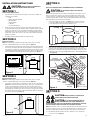
1. Install the rails into the mounting channel on the housing. Center the mounting channel in
the slots on the housing, then from inside the housing tighten the mounting channel nuts
so the channel is securely in place. Position the housing next to the joist. Line up housing
so that it will be flush with the finished ceiling. Secure the ends of the rails with screws or
nails (not included) to the joists and slide the housing into the final position (Figure 1).
SECTION 3
Existing Construction
NOTE: If the mounting flange is installed on the fan housing, remove the two screws that
connect the ceiling mounting flange to the housing and set aside (Figure 12).
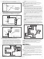
1. Set housing in position between the joist and trace an outline onto the ceiling material
(Figure 2). Set housing aside and cut opening, being careful not to cut or damage any
electrical or other hidden utilities. Install the rails into the mounting channel on the
housing. Center the mounting channel in the slots on the housing, then from inside the
housing tighten the mounting channel nuts so the channel is securely in place. Position
the housing in the previously cut hole so that it is flush with the finished ceiling. Secure
the ends of the rails to the joists (Figure 1).
www.airkinglimited.com
6727902 Rev. D 10-16 2 of 12
SECTION 4
Ducting
NOTE: 6" OR LARGER RIGID DUCT IS RECOMMENDED FOR BEST PERFORMANCE.
CAUTION: ALL DUCTING MUST COMPLY WITH LOCAL AND
NATIONAL BUILDING CODES.
NOTE: The ducting from this fan to the outside of the building has a strong effect on the air
flow, noise and energy use of the fan. Use the shortest, straightest duct routing possible
for best performance, and avoid installing the fan with smaller ducts than recommended.
Insulation around the ducts can reduce energy loss and inhibit mold growth. Fans installed
with existing ducts may not achieve their rated air flow.
1. Connect the ducting to the fan’s duct collar (Figure 3). Secure in place using tape
or screw clamp. Always duct the fan to the outside through a wall or roof cap. It is
recommended that low restriction termination fittings be used.
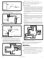
2. Ensure duct joints and exterior penetrations are sealed with caulk or other similar
material to create an air-tight path to minimize building heat loss or gain and to reduce
the potential for condensation. Place/wrap insulation around duct and/or fan to in order
to minimize possible condensation buildup within the duct, as well as building heat loss
or gain (Figure 4).
SECTION 5
Wiring
CAUTION: MAKE SURE POWER IS SWITCHED OFF AT
SERVICE PANEL BEFORE STARTING INSTALLATION.
CAUTION: ALL ELECTRICAL CONNECTIONS MUST BE
MADE IN ACCORDANCE WITH LOCAL CODES, ORDINANCES, OR
NATIONAL ELECTRICAL CODE. IF YOU ARE UNFAMILIAR WITH METHODS OF INSTALLING
ELECTRICAL WIRING, SECURE THE SERVICES OF A QUALIFIED ELECTRICIAN.
NOTE: This unit includes a side access panel for wiring that does not require the removal of the
fan’s blower assembly. If you choose to wire the unit from the inside, you will need to remove
the blower assembly and internal wiring compartment. Both methods are equally effective.
1a. External Wire Compartment: Remove the wire compartment cover screw and place
cover in a secure place (Figure 5).
Ducting
Duct
Collar
Figure 3
Figure 2
Joist
Housing
Joist
Mounting Rails
Figure 1
Figure 4
Insulation*
(place around and
over Fan Housing
Fan Housing
Power Cable*
Seal gaps
around Housing
Round
Duct*
Seal duct joints
with tape
Round
Elbows*
Wall Cap*
Roof Cap*
(with built-in
damper)
Keep duct
runs short
*Purchase separately
or

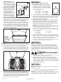
1b. Internal Wire Compartment: If the motor is already installed in the housing, remove the
two screws holding the blower assembly in place. Lift up on the assembly and slide it
out of the tabs on the housing (Figure 6). Remove the wire compartment cover screw
and place the cover in a secure place (Figure 7).
NOTE: If the fan motor plug is connected to the fan housing receptacle, unplug so the blower
assembly can be completely removed.
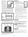
Standard and Motion Sensing Models
2. Connect the White wire of the fan to the White (Neutral) wire from the power source.
Connect the ground wire from the house to the green wire from the fan housing. Using
a properly grounded three function switch (not included) connect the Black wire from
the supply to the switch. Connect the Black wire (fan) from the fan housing to one of the
terminals on the switch. Connect the Red wire (light) from the fan housing to a separate
terminal on the switch. Connect the Purple wire (night light) from the fan housing to a
separate terminal on the switch (Figure 8). Use approved methods for all connections.
www.airkinglimited.com
6727902 Rev. D 10-16 3 of 12
NOTE: There may be more than one white wire to be connected present.
NOTE: The fan’s receptacle wires might need to be pulled outside compartment for connection.
Only pull the five loose wires outside of compartment. Additional wires will be present.
NOTE: Unit must be grounded according to all local and national codes.
Humidity Sensing Models
3a. For proper operation the humidity sensing fan will require a 3 way switch (not included).
Run wiring between the fan and the switch location. Make sure you leave enough wiring
in each box to make the connections. At the switch box connect the black wire from the
house to the common terminal of the switch. Connect the black wire from the fan to one
of the switched terminals on the switch. This position will energize the automatic mode
and the fan will energize upon a rise in humidity. Connect the yellow wire from the fan
to the other switched terminal on the switch. This position will activate the Manual On
feature and energize the fan. Properly connect the ground and neutral (if applicable)
mount the switch and the cover.
NOTE: The yellow wire may contain a wire crimp nut which will have to be cut off and
the wire stripped.
3b. Wiring the Fan: From where you have chosen to access the fan’s junction box, connect
the white wire from the house to the white wire from the fan. Connect the wire from the
automatic position on the wall switch to the black wire from the fan, connect the wire
from the manual On position on the switch to the yellow wire from the fan. Connect the
ground wire from the house to the green wire from the fan housing (Figure 10). Use
approved methods for all connections.
NOTE: The yellow wire may contain a wire crimp nut which will have to be cut off and
the wire stripped.
3c. Wiring the Lights: Using a properly grounded standard wall switch, connect the black
wire from the supply to one side of the switch. Connect the Red wire (light) from the fan
housing to one of the terminals on the switch. Connect the Purple wire (night light) from
the fan housing to a separate terminal on the switch. (Figure 9). Use approved methods
for all connections.
4. Carefully tuck wire back inside wire compartment and replace wire compartment cover
securing with the screw that was removed earlier.
NOTE: The fan’s receptacle wires might need to be pulled outside compartment for connection.
Only pull the five loose wires outside of compartment. Additional wires will be present.
NOTE: Unit must be grounded according to all local and national codes.
SECTION 6
Completing the Installation
1. Use a sealant appropriate for contact with the building materials present and for the
temperature requirements of the installation to prevent air leakage from unconditioned
spaces is recommended. If gaps between unit housing and ceiling are great, additional
material (backing rod, ceiling material) may be required.
NOTE: This fan is rated for direct insulation contact (Type IC) and it is recommended that this fan
be completely covered by insulation in order to reduce heat loss or gain to unconditioned space.
2. If the fan’s blower assembly was removed during the wiring process, reinstall the
blower by reversing the directions in Section 5 (Wiring), Step 1b.
Figure 5
Screw
Wire
Compartment
Cover
Screw
Wire Compartment
Cover
Figure 7
NOTE: Wire compartment configuration
will be dependent on model.
Figure 9
Supply from house
Black
Neutral (White)
Ground (Green or Bare)
Fan
Black
Neutral (White)
Green
Switch
Black
Purple
Red
Switch
Yellow
Figure 8
Supply from house
Black
Neutral (White)
Ground (Green or Bare)
Fan
Neutral (White)
Green
Switch
Black
Purple
Red
Tabs
Screws
Figure 6
3
4
5
6
7
8
9
1
0
1
1
1
2
1
3
O
F
F
(x10)

3a. STANDARD MODELS: Plug the fan’s
quick connect motor cord into the
corresponding receptacle located on
the wire compartment cover. This cord
will only fit one way into the receptacle
(Figure 10).
3b. HUMIDITY SENSING MODELS: Plug the
fan’s quick connect motor cord into the
corresponding receptacle located on the
wire compartment cover. Connect the
two pin connector from the humidistat
compartment to the two pin connector
from the side of the wire compartment
cover. These cords will only fit one way
into the receptacles (Figure 10).
3c. MOTION SENSING MODELS: Plug the fan’s quick connect motor cord into the
receptacle located on the side of the wire compartment cover. Plug the 6 pin quick
connect cord from the grill into the 6 pin receptacle located on the top of the wire
compartment cover. These cords will only fit one way into the receptacles (Figure 10).
4. Install the ceiling mounting flange to cover any gaps which exist between the housing
and the finished ceiling. Remove the two screws that connect the ceiling mounting
flange to the housing. Put sealant (not provided) on inside edge of the ceiling mounting
flange to ensure that the flange is sealed to the ceiling. Line up the screw holes in the
ceiling mounting flange with the screw holes on the inside of the housing and press
flange in place so it is tight against the ceiling. Reinstall ceiling flange mounting screws
inside the housing (Figure 11).
NOTE: If the housing is mounted to far or not far enough into the ceiling for the flange to make
a solid connection, loosen the mounting channel and adjust the housing up or down on the
rails. Once in place, fully tighten the mounting channel nuts.
5. Install the grill by squeezing the springs together and installing it up into the slot furthest
from the wire compartment on the fans housing. Attach the 6 pin quick connect from the
grill to the 6 pin connector on the top of the wire cover. The cord will only fit one way into
the receptacle. Install the other spring and push the grill up into position. (Figure 12).
6. Open the light lens on the grill by pushing into the lens and allowing in to spring open.
Install the included LED lamp into the lamp holder by lining up the pins on the lamp base
to the socket of the lamp holder and turning the lamp body clockwise until the lamp
snaps into place and is firmly seated in the lamp holder. Install a 4 watt maximum type C7
(candelabra base) night light (not included) into the side lamp holder.
7. Restore power and test your installation.
www.airkinglimited.com
6727902 Rev. D 10-16 4 of 12
SECTION 7
Programming the Occupancy Sensor
1a. Setting the Occupancy Time Delay. This will set the amount
of time the fan will continue to operate on high speed after the
room is vacated. Locate the motion sensor on the fan’s grill and
press the button 2 times. The LED on the sensor will then flash
the number of times to indicate the current setting, this will
repeat 3 times:
1 time = 30 seconds
2 times = 2.5 minutes 6 times = 12.5 minutes
3 times = 5 minutes 7 times = 15 minutes
4 times = 7.5 minutes 8 times = 17.5 minutes
5 times = 10 minutes 9 times = 20 minutes
1b. To adjust the setting, while the sensor is still flashing from Step 1a, press the button the
number of times that corresponds with the amount of time you desire, for instance 3 times
sets the delay to 5 minutes (see numbers in Step 1). The sensor will then flash the number
of times for the new setting 3 times before exiting back to the programming mode.
2a Setting the Minimum On Time. This sets the minimum time the fan will operate on
high speed once motion is detected within the room. This works in conjunction with
the Occupancy Time Delay feature set in Steps 1a and 1b. For instance if you set the
minimum time on for 15 minutes and the Time Delay for 5 minutes, the fan will operate
for at least 15 minutes then 5 additional minutes.
NOTE: This is a minimum time that the fan will operate. If the room is occupied longer, the
fan will continue to run until the room is vacated and the occupancy time delay has elapsed.
2b. Locate the motion sensor on the fan’s grill and press the button 10 times. The LED on the
sensor will then flash the number of times to indicate the current setting, this will repeat
3 times:
1 time = 0 minutes 4 times = 45 minutes
2 times = 15 minutes 5 times = 60 minutes
3 times = 30 minutes
2c. To adjust the setting, while the sensor is still flashing from Step 2b, press the button
the number of times that corresponds with the amount of time you desire, for instance
3 times sets the minimum on time to 30 minutes (see numbers in Step 2b). The sensor
will then flash the number of times for the new setting 3 times before exiting back to the
programming mode.
3. Once all setting have been made and the sensor will return to detection mode and the
LED will flash when occupancy of the room is detected.
SECTION 8
Setting the Humidistat
This fan may be equipped with a humidity sensor that automatically turns the fan on when
humidity is above set point and off when humidity is at or below set point. If the fan is operating
too long or not enough, first check to see the humidity sensor set point. In cases where the
ambient humidity level of the room rises higher than the preset level, the fan will turn on even if
the room is not occupied. This helps prevent conditions that lead to mold growth.
CAUTION: MAKE SURE POWER IS SWITCHED OFF AT
SERVICE PANEL BEFORE SERVICING THE UNIT.
1. To set the desired humidity level of the room, remove the grill and locate the
dehumidistat dial located on the wire compartment cover.
2. Set the dial to the relative humidity you want the fan to maintain usually between 50 &
80%. Moist climates will require higher settings than dry climates. When the humidity level
of the room is below this setting the fan will remain off. When the humidity level rises about
this setting the fan will turn on and run until the humidity level falls below this setting.
3. Reinstall the grill and restore power.
SECTION 9
Setting the Speed
This unit features a variable speed function that allows it to be set from 30 to 130 CFM. To
adjust the airflow:
1. Remove the grill and find the adjustment post on the top of the wire compartment.
2. Turn the post to the desired CFM setting then reinstall the grill.
NOTE: The motor will adjust to the static pressure of the installation to maintain the desired
CFM. For higher speeds / higher static pressure installations, airflow testing may be required
to insure the proper amount of ventilation.
Figure 12
Figure 11
Screws
Ceiling
Mounting
Flange
Screw Holes
Figure 10
Motion
Fan
Humidity

www.airkinglimited.com
6727902 Rev. D 10-16 5 of 12
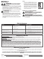
Troubleshooting Guide
Trouble Probable Cause Suggested Remedy
1. Fan does not operate when the switch is on. 1a. A fuse may be blown or a circuit tripped. 1a. Replace fuse or reset circuit breaker.
1b. Connector plug from motor is not plugged in. 1b. Turn off power to unit. Remove Grill and plug motor into receptacle
in housing. Restore power to unit.
1c. Wiring is not connected properly. 1c. Turn off power to unit. Check that all wires are connected.
1d Motor has stopped operating. 1d. Replace motor.
2. Fan is operating, but air moves slower than normal. 2. Obstruction in the exhaust ducting. 2. Check for any obstructions in the ducting. The most common are bird
nests in the roof cap or wall cap where the fan exhausts to the outside.
3. Fan is operating louder than normal 3a. Motor is loose. 3a. Turn off power to unit. Remove grill and check that all screws are fully
tightened. Restore power to unit.
3b. Fan blade is hitting housing of unit. 3b. Call your dealer for service.
Installer: Installation Date:
Place of Purchase: Model Number:
LIMITED WARRANTY
WHAT THIS WARRANTY COVERS: This product is warranted against defects in workmanship and/or materials.
HOW LONG THIS WARRANTY LASTS: This warranty extends only to the original purchaser of the product and lasts for five (5) years from the date of original purchase or until the original
purchaser of the product sells or transfers the product, whichever first occurs.
WHAT AIR KING WILL DO: During the warranty period, Air King will, at its sole option, repair or replace any part or parts that prove to be defective or replace the whole product with the
same or comparable model.
WHAT THIS WARRANTY DOES NOT COVER: This warranty does not apply if the product was damaged or failed because of accident, improper handling, installation, or operation, shipping
damage, abuse, misuse, unauthorized repairs made or attempted. This warranty does not cover shipping costs for the return of products to Air King for repair or replacement. Air King will pay
return shipping charges from Air King following warranty repairs or replacement
ANY AND ALL WARRANTIES, EXPRESSED OR IMPLIED (INCLUDING, WITHOUT LIMITATION, ANY IMPLIED WARRANTY OF MERCHANTABILITY), LAST ONE YEAR FROM THE DATE
OF ORIGINAL PURCHASE OR UNTIL THE ORIGINAL PURCHASER OF THE PRODUCT SELLS OR TRANSFERS THE PRODUCT, WHICHEVER FIRST OCCURS AND IN NO EVENT SHALL AIR
KING’S LIABILITY UNDER ANY EXPRESS OR IMPLIED WARRANTY INCLUDE (I) INCIDENTAL OR CONSEQUENTIAL DAMAGES FROM ANY CAUSE WHATSOEVER, OR (II) REPLACMENT OR
REPAIR OF ANY HOUSE FUSES, CIRCUIT BREAKERS OR RECEPTACLES. NOTWITHSTANDING ANYTHING TO THE CONTRARY, IN NO EVENT SHALL AIR KING’S LIABILITY UNDER ANY EX-
PRESS OR IMPLIED WARRANTY EXCEED THE PURCHASE PRICE OF THE PRODUCT AND ANY SUCH LIABILITY SHALL TERMINATE UPON THE EXPIRATION OF THE WARRANTY PERIOD.
Some states and provinces do not allow limitations on how long an implied warranty lasts, or the exclusion or limitation of incidental or consequential damages, so these exclusions or limitations
may not apply to you. This warranty gives you specific legal rights. You may also have other rights which vary from state to state and province to province. Proof of purchase is required before a
warranty claim will be accepted.
CUSTOMER SERVICE:
Toll-Free (800) 465-7300
Our Customer Service team is available to assist you with product questions, service center locations, and replacement parts. They can be reached Monday through Friday, 8am-4pm Eastern.
Please have your model number available, as well as the type and style (located on the label inside of your product).
Please do not return product to place of purchase.
www.airkinglimited.com
PARTS FOR DISCONTINUED, OBSOLETE AND CERTAIN OTHER PRODUCTS MAY NOT BE AVAILABLE. DUE TO SAFETY REASONS, MANY ELECTRONIC COMPONENTS AND MOST
HEATER COMPONENTS ARE NOT AVAILABLE TO CONSUMERS FOR INSTALLATION OR REPLACEMENT.
SECTION 10
Use and Care
CAUTION: MAKE SURE POWER IS SWITCHED OFF AT
SERVICE PANEL BEFORE SERVICING THE UNIT.
1. Cleaning the Grill: Remove grill and use a mild detergent, such as dishwashing liquid,
and dry with a soft cloth. NEVER USE ANY ABRASIVE PADS OR SCOURING POWDERS.
Completely dry grill before reinstalling. Refer to instructions in Section 6 Completing the
Installation, to reinstall grill.
2. Cleaning the Fan Assembly: Wipe all parts with a dry cloth or gently vacuum the fan.
NEVER IMMERSE ELECTRICAL PARTS IN WATER.
CAUTION: ALLOW BULBS TO COOL BEFORE REPLACING.
3. Changing the Lamp: Disconnect power to the unit. Open the light lens on the grill by
pushing into the lens and allowing in to spring open. Remove lamp by gently twisting the
lamp base counterclockwise while applying outward pressure. Installation is the reverse of
removal. Replace with Air King model AK8LED40 or a compatible GU24 8 watt LED lamp.
Night Light: Unscrew night light bulb from socket and replace with a 4 watt maximum
type C7 (candelabra base) night light bulb.
Fuse
1. Follow the steps in SECTION 5 Wiring to gain access to the
fuse holder located inside the wire compartment. To replace
the fuse, squeeze the top an bottom of the fuse holder together
while twisting the larger piece in a direction away from the
tabs (Figure 13). Replace fuse only with 0.5 Amp, 250VAC, 5 x
20mm, Fast Acting fuse. Reconnect the fuse holder by lining up
the top an bottom section and squeeze together while twisting
until they are locked in place. Carefully tuck back into the wire
compartment and reinstall the wire compartment cover.
CALIFORNIA RESIDENTS ONLY:
WARNING: THIS PRODUCT CAN EXPOSE YOU TO A CHEMICAL [OR
CHEMICALS] KNOWN TO THE STATE OF CALIFORNIA TO CAUSE CANCER.
WARNING: THIS PRODUCT CAN EXPOSE YOU TO A CHEMICAL
[OR CHEMICALS] KNOWN TO THE STATE OF CALIFORNIA TO CAUSE
REPRODUCTIVE TOXICITY.
Figure 13

www.airkinglimited.com
6727902 Rev. D 10-16 6 of 12
3
7
13
14
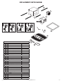
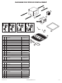
REPLACEMENT PARTS DIAGRAM
1
2
4
5
6
All Models
# Qty. Description Replacement Part #
1 4 Mounting Rails 5S1299002
2 1 6" Metal Collar Assembly 5S5299100
3 2 Grill Springs 5S1202046
4 1 Ceiling Flange 5S1202050
5 2 Mounting Channel 5S1202123
6 1 Blower Assembly 5S1250100
12 1 Fuse Harness Assembly 5S1250011
13 1 Light Lens 5S1239116
14 1 8 Watt LED Lamp 5S1250001
Specific to Model DL4S
# Qty. Description Replacement Part #
7 1 Grill Assembly 5S1250105
8 1 Wire Compartment Assembly 5S1250105
Specific to Model DL4SG
# Qty. Description Replacement Part #
7 1 Grill Assembly 5S1250106
9 1 Wire Compartment Assembly 5S1250108
Specific to Model DL4SH
# Qty. Description Replacement Part #
7 1 Grill Assembly 5S1250105
10 1 Wire Compartment Assembly 5S1250109
15 1 Knob 5S1299802
16 1 Humidity Sensor Compartment 5S1239826
Specific to Models DL4SGH
# Qty. Description Replacement Part #
7 1 Grill Assembly 5S1250106
11 1 Wire Compartment Assembly 5S1250110
15 1 Knob 5S1299802
16 1 Humidity Sensor Compartment 5S1239826
15
11
16
12
15
10
16
12
9
12
8
12

INSTRUCTIONS IMPORTANTES –
MODE D’EMPLOI
CONSERVER CES INSTRUCTIONS
www.airkinglimited.com
6727902 Rev. D 10-16 7 of 12
Ventilateur combiner, comprend
lumière et ventilation
Modèles: DL4S, DL4SG,
DL4SH, DL4SGH
LIRE ET CONSERVER CES INSTRUCTIONS
LIRE SOIGNEUSEMENT AVANT DE TENTER D’ASSEMBLER, INSTALLER, OPÉRER OU DE
RÉPARER LE PRODUIT DÉCRIT. PROTÉGEZ VOUS-MÊME ET LES AUTRES EN OBSERVANT
TOUTE L’INFORMATION DE SÉCURITÉ. FAILLIR À SE CONFORMER AUX INSTRUCTIONS PEUT
RÉSULTER EN BLESSURE PERSONNELLE GRAVE ET/OU EN DOMMAGE À LA PROPRIÉTÉ.
CONSERVER CES INSTRUCTIONS POUR RÉFÉRENCES FUTURES.
INSTRUCTIONS GÉNÉRALES DE SÉCURITÉ
Lors de l’utilisation d’appareils électriques, des précautions
de base doivent toujours être suivies pour réduire les risques
d’incendie, de choc électrique et de blessures corporelles, incluant ce qui suit:
AVERTISSEMENT : POUR RÉDUIRE
LES RISQUES D’INCENDIE, DE CHOC ÉLECTRIQUE
OU DE BLESSURES PERSONNELLES OBSERVER CE QUI SUIT:
a) Utiliser cette unité seulement de la manière pour laquelle le fabricant l’a
conçu. Si vous aviez des questions, veuillez contacter le fabricant.
b) Avant d’effectuer un service ou de nettoyer l’unité, couper
l’alimentation électrique dans le panneau de distribution et verrouiller
le dispositif de déconnexion afin d’éviter que l’alimentation ne
revienne accidentellement. Lorsque le dispositif ne peut être
verrouillé, fixer solidement un avis d’avertissement, tel qu’une
étiquette, au panneau de distribution.
AVERTISSEMENT : POUR RÉDUIRE
LES RISQUES D’INCENDIE, DE CHOC ÉLECTRIQUE
OU DE BLESSURES PERSONNELLES OBSERVER CE QUI SUIT:
a) Le travail d’installation et le câblage électrique doivent être effectués par
une(des) personne(s) qualifiée(s) en conformité avec tous les codes et
normes applicables, incluant la construction relative aux incendies.
b) De l’air en quantité suffisante est requis pour la bonne combustion
et l’évacuation de gaz par le conduit (cheminée) provenant d’équipement
de brûlage au combustible pour prévenir un
refoulement. Suivre les directives du fabricant de l’équipement de
chauffage et les normes de sécurité telles que celles publiées par la
National Fire Protection Association (NFPA) et de la American Society for
Heating, Refrigeration, and Air Conditioning Engineers (ASHRAE), et de
celles des autorités locales du code.
c) Lors de coupe ou de perçage des murs et plafonds, ne pas
endommager le filage électrique et autres utilités cachées.
ATTENTION : POUR USAGE DE VENTILATION
GÉNÉRALE EXCLUSIVEMENT. NE PAS UTILISER POUR
ÉVACUER DU MATÉRIEL ET DES VAPEURS DANGEREUSES OU EXPLOSIVES.
d) Les ventilateurs avec conduits doivent toujours être évacués vers
l’extérieur
e) Si cet appareil doit être installé au-dessus d’une baignoire ou d’une
douche, il doit être marqué comme approprié pour l’application et
connecté à un DDFT (disjoncteur différentiel de fuite à la terre) - circuit
de dérivation protégé.
f) Ne pas installer dans un plafond avec une valeur d’isolation thermique
supérieure à R40.
g) Cette unité doit être mise à la terre
h) Pour éviter des dommages aux roulements des moteurs et/ou des
hélices bruyantes ou déséquilibrées, empêcher la poussière de cloison
sèche, poussière de construction, etc., d’atteindre l’unité de puissance.
i) Lire toutes les instructions avant d’installer ou d’utiliser la ventilateur.
AVERTISSEMENT : POUR RÉDUIRE
LES RISQUES D’INCENDIE OU DE CHOC
ÉLECTRIQUE, NE PAS UTILISER CE VENTILATEUR AVEC UN RÉGULATEUR
DE VITESSE ÉLECTRONIQUE.
AVERTISSEMENT : NE PAS UTILISER DANS LES
CUISINES
AVERTISSEMENT : LA CANALISATION DE CE
VENTILATEUR À L’EXTÉRIEUR DU BÂTIMENT A UN EFFET
IMPORTANT SUR LE FLUX D’AIR, LE BRUIT ET LA CONSOMMATION
D’ÉNERGIE DU VENTILATEUR. UTILISEZ LA ROUTE DE CANALISATION
LA PLUS COURTE ET LA PLUS DROITE POSSIBLE POUR UNE MEILLEURE
PERFORMANCE, ET ÉVITEZ D’INSTALLER LE VENTILATEUR AVEC
DES CONDUITS PLUS PETITS QUE RECOMMANDÉ. L’ISOLATION
AUTOUR DES CONDUITS PEUT RÉDUIRE LA PERTE D’ÉNERGIE ET
EMPÊCHER LE DÉVELOPPEMENT DE MOISISSURES. IL SE PEUT QUE
LES VENTILATEURS INSTALLÉS AVEC DES CONDUITS EXISTANTS
N’ATTEIGNENT PAS LEUR DÉBIT D’AIR NOMINAL.

SECTION 4
Conduits
NOTE: UN CONDUIT PLUS RIGIDE DE 6 PO OU PLUS EST RECOMMANDE POUR UNE
MEILLEURE PERFORMANCE.
ATTENTION : TOUS LES CONDUITS DOIVENT ÊTRE CONFORMES
AUX CODES DU BÂTIMENT LOCAUX ET NATIONAUX.
REMARQUE : La canalisation de ce ventilateur à l’extérieur du bâtiment a un effet important sur
le flux d’air, le bruit et la consommation d’énergie du ventilateur. Utilisez la route de canalisation
la plus courte et la plus droite possible pour une meilleure performance, et évitez d’installer le
ventilateur avec des conduits plus petits que recommandé. L’isolation autour des conduits peut
réduire la perte d’énergie et empêcher le développement de moisissures. Il se peut que les
ventilateurs installés avec des conduits existants n’atteignent pas leur débit d’air nominal.
1. Raccorder le conduit au collet de conduit du ventilateur (Figure 3). Fixer en place à
l’aide de ruban ou de serre-joint. Toujours évacuer le ventilateur vers l’extérieur au
travers de chapeau mural ou de toit. Il est recommandé que les raccords d’extrémité
basse de restriction sont utilisées.
2. Assurez-vous que les joints des conduits et les pénétrations extérieures sont scellés avec du
mastic ou tout autre matériau similaire pour créer un passage d’air étanche afin de minimiser
la perte ou le gain de chaleur et réduire le risque de condensation. Placez / enveloppez
l’isolant autour du conduit et / ou ventilateur afin de minimiser la possibilité d’accumulation
de condensation à l’intérieur du conduit, ainsi que la perte ou le gain de chaleur (Figure 4).
SECTION 5
Câblage
ATTENTION : VOUS ASSURER QUE L’ALIMENTATION
EST COUPÉE AU PANNEAU DE SERVICE AVANT DE COMMENCER
L’INSTALLATION.
ATTENTION : TOUTES LES CONNEXIONS DOIVENT ÊTRE
FAITES EN CONFORMITÉ AVEC LES CODES ÉLECTRIQUES LOCAUX OU
NATIONAUX. SI VOUS N’ÊTES PAS FAMILIER AVEC LES MÉTHODES D’INSTALLATION DE
CÂBLAGE ÉLECTRIQUE, RECOURREZ AUX SERVICES D’UN ÉLECTRICIEN QUALIFIÉ.
REMARQUE: Cette unité possède un panneau d’accès latéral pour le câblage qui ne requiert
pas l’enlèvement de l’assemblage de la soufflante du ventilateur. Si vous choisissez de
raccorder l’unité par l’intérieur, vous aurez besoin d’enlever l’assemblage de la soufflante et le
compartiment de câblage intérieur. Les deux méthodes sont également efficaces.
INSTRUCTIONS D’INSTALLATION
ATTENTION : VOUS ASSURER QUE L’ALIMENTATION
EST COUPÉE AU PANNEAU DE SERVICE AVANT DE COMMENCER
L’INSTALLATION.
SECTION 1
Préparation du Ventilateur d’évacuation
1. Sortir le ventilateur de sa boite et confirmer que toutes les pièces sont présentes. En
plus du ventilateur d’évacuation vous devriez avoir :
1 - Grille
1 - Ensemble de clapet (attaché)
4 - Supports de montage
1 - Bride de montage
1 - Ampoule de type LED
1 - Feuillet d’instructions / sécurité
2. Choisir un emplacement pour votre ventilateur. Pour garantir la meilleure qualité d’air
et performance acoustique, il est recommandé que la longueur de la canalisation et le
nombre de coudes soient réduits au minimum, que le rayon de chaque coude soit aussi
grand que possible pour l’installation, et que des conduits rigides isolés soient utilisés.
Ce ventilateur nécessitera au moins 20,3cm (8po) de dégagement dans le plafond ou le
mur, et s’installe au travers de cloison sèche d’une épaisseur de jusqu’à 1,9cm (3/4po).
3. Aucun matériel amortissant de vibrations supplémentaire n’est nécessaire pour ce
ventilateur.
SECTION 2
Nouvelle Construction
REMARQUE : Si la bride de montage est installée sur le boîtier du ventilateur, enlevez les deux
vis qui relient la bride de montage du plafond au boîtier et mettez de côté (Figure 11).
1. Installez les rails dans le canal de montage sur le boîtier. Centrez le canal de montage
dans les fentes sur le boîtier, puis de l’intérieur du boîtier, serrez les écrous montage de
sorte que le canal soit bien en place. Placez le boîtier à côté de la solive. Aligner le châssis
pour qu’il soit de niveau avec le plafond fini. Fixez les extrémités des rails aux solives avec
des vis ou des clous (non inclus) et glissez le boîtier dans la position finale (Figure 1).
SECTION 3
Construction Existante
REMARQUE : Si la bride de montage est installée sur le boîtier du ventilateur, enlevez les deux
vis qui relient la bride de montage du plafond au boîtier et mettez de côté (Figure 11).
1. Placer le boîtier en place entre les solives et tracez un contour sur le matériel du plafond
(Figure 2). Mettez le boîtier de côté et découpez l’ouverture, en faisant attention de ne pas
couper ou endommager les installations électriques ou d’autres utilités masquées. Installez
les rails dans le canal de montage sur le boîtier. Centrez le canal de montage dans les fentes
sur le boîtier, puis de l’intérieur du boîtier serrez les écrous de montage de sorte que le canal
soit bien en place. Positionnez le boîtier dans le trou préalablement découpé de sorte qu’il
soit aligné avec le plafond fini. Fixez les extrémités des rails aux solives (Figure 1).
www.airkinglimited.com
6727902 Rev. D 10-16 8 of 12
Conduits
Collet du
Conduit
Figure 3
Châssis
Solive
Traverses de
Montage
Figure 1
Figure 2
Solive
Figure 4
Isolant*
(placer autour et au-
dessus du logement
du ventilateur)
Logement du ventilateur
Câble d’alimentation*
Sceller les
espaces autour
du logement
Conduit
rond*
Sceller les joints
avec du ruban
Coudes
ronds*
Capuchon de mur*
Capuchon de toit*
(avec amortisseur
intégré)
Garder les
canalisations courtes
*Acheter séparément
ou

1a. Compartiment de Câblage Extérieur : Enlever la vis du couvercle du compartiment à
câblage et mettre ce couvercle dans un endroit fiable (Figure 5).
1b. Compartiment de Câblage Intérieur: Si le moteur est déjà installé dans le boîtier, enlevez
les deux vis maintenant l’unité de ventilation en place. Soulevez le l’unité et faites-la
glisser hors des languettes sur le boîtier (Figure 6). Retirez la vis du couvercle du
compartiment de câblage et placez le couvercle dans un endroit sûr (Figure 7).
REMARQUE : Si le raccord du moteur de ventilateur est raccordé au réceptacle du châssis, le
débrancher afin que l’assemblage de la soufflante soit complètement enlevé.
Modèles standards et avec détection de mouvement
2. Connectez le fil blanc du ventilateur au fil blanc (neutre) de la source d’alimentation.
Connectez le fil de terre de la maison au fil vert du boîtier du ventilateur. En utilisant un
commutateur à trois fonctions correctement mis à la terre (non inclus), connectez le fil noir
de l’alimentation au commutateur. Connectez le fil noir (ventilateur) à partir du boîtier du
ventilateur à l’une des bornes sur le commutateur. Connectez le fil rouge (lumière) du boîtier
du ventilateur à un terminal séparé sur le commutateur. Connectez le fil violet (lumière de
nuit) du boîtier de ventilateur à un terminal séparé sur le commutateur (Figure 8). Utilisez
des méthodes approuvées pour toutes les connexions.
www.airkinglimited.com
6727902 Rev. D 10-16 9 of 12
Figure 5
Vis
Couvercle du
Compartiment
de Câblage
REMARQUE : Il peut y avoir plus d’un fil blanc à connecter.
REMARQUE : Les fils du réceptacle du ventilateur pourraient nécessiter d’être tirés à
l’extérieur du compartiment pour le raccordement. Tirer uniquement les trois fils lâches à
l’extérieur du compartiment. Des fils additionnels y sont présents.
REMARQUE : L’unité doit être mise à la terre selon les codes locaux et nationaux.
Modèles avec détection d’humidité
3a. Câblage du ventilateur : Pour un bon fonctionnement, le ventilateur de détection
d’humidité exigera un interrupteur à 3 voies (non inclus). Faites passer le câblage entre
le ventilateur et l’emplacement du commutateur. Assurez-vous de laisser suffisamment
de câblage dans chaque boîte pour faire les connexions. À la boîte de commutation,
connectez le fil noir de la maison à la borne commune du commutateur. Connectez le
fil noir du ventilateur à l’une des bornes commutées sur le commutateur. Cette position
activera le mode automatique et le ventilateur s’activera après une élévation d’humidité.
Connectez le fil jaune du ventilateur à l’autre borne commutée sur le commutateur. Cette
position activera le mode manuel et activera le ventilateur. Connectez correctement le fil
de terre et neutre (le cas échéant), installez le commutateur et le couvercle.
REMARQUE : Le fil jaune peut contenir un écrou de fil à sertir qui devra être coupé et le
fil dénudé.
3b. À partir de l’endroit où vous avez choisi d’accéder à la boîte de jonction du ventilateur,
connectez le fil blanc de la maison au fil blanc du ventilateur. Connectez le fil de la
position automatique sur l’interrupteur mural au fil noir du ventilateur, connectez le fil
de la position manuelle sur l’interrupteur au fil jaune du ventilateur. Connectez le fil de
terre de la maison au fil vert du boîtier du ventilateur (Figure 9). Utiliser des méthodes
approuvées pour toutes les connexions.
REMARQUE : Le fil jaune peut contenir un écrou de fil à sertir qui devra être coupé et le
fil dénudé.
3c. Câblage des lumières : Utilisez un interrupteur mural standard correctement mise à
la terre, connectez le fil noir de l’alimentation d’un côté de l’interrupteur. Branchez le fil
rouge (lumière) du boîtier du ventilateur à l’une des bornes sur le commutateur. Connectez
le fil violet (lumière de nuit) du boîtier du ventilateur à un terminal séparé sur l’interrupteur.
(Figure 9). Utilisez des méthodes approuvées pour toutes les connexions.
4. Regrouper soigneusement les fils à l’intérieur du compartiment pour le raccordement et
replacer le couvercle du compartiment en le fixant avec la vis qui fut enlevée précédemment.
REMARQUE : Les fils du réceptacle du ventilateur pourraient nécessiter d’être tirés à
l’extérieur du compartiment pour le raccordement. Tirer uniquement les trois fils lâches à
l’extérieur du compartiment. Des fils additionnels y sont présents.
REMARQUE : L’unité doit être mise à la terre selon les codes locaux et nationaux.
SECTION 6
Complétion de l’installation
1. Il est recommandé d’utiliser un scellant approprié pour le contact avec les matériaux
de construction actuels et pour les besoins de la température de l’installation, afin
d’empêcher les fuites d’air à partir des espaces non conditionnés. S’il y a des grands
écarts entre le boîtier de l’appareil et le plafond, du matériel supplémentaire (tige de
support, matériel de plafond) peut être nécessaire.
NOTE : Ce ventilateur est conçu pour le contact d’isolation directe (type IC). Il est aussi
recommandé que ce ventilateur soit complètement recouvert par l’isolation afin de réduire la
perte de chaleur ou de gagner de l’espace inconditionné.
2. Si l’assemblage de la soufflante du ventilateur a été enlevé durant le processus de
raccordement, réinstaller la soufflante en inversant les instructions à l’étape 1b de la
Section 5 Câblage.
REMARQUE : Vous pouvez aussi trouver un connecteur supplémentaire à 2 broches avec
du ruban adhésif. Il est utilisé pour la vitesse d’impulsion. Voir la section 9 (activation de la
vitesse d’impulsion) pour plus de détails.
Figure 9
Alimentation du logement
Noir
Neutre (Blanc)
Mise à la terre
(vert ou nu)
Ventilateur
Noir
Neutre (Blanc)
Vert
Commutateur
Noir
Rouge
Commutateur
Jaune
Vis
Couvercle du
Compartiment
de Câblage
Figure 7
REMARQUE : La configuration du
compartiment de fil dépendra du modèle.
Figure 8
Alimentation du logement
Neutre (Blanc)
Mise à la terre
(vert ou nu)
Ventilateur
Neutre (Blanc)
Vert
Commutateur
Noir
Violet
Rouge
Noir
Onglets
Vis
Figure 6
3
4
5
6
7
8
9
1
0
1
1
1
2
1
3
O
F
F
(x10)

3a. MODÈLES STANDARDS: branchez le
cordon de connexion rapide du moteur du
ventilateur dans la prise correspondante
située sur le couvercle du compartiment de
fil. Ce cordon ne peut être inséré que d’une
seule manière dans la prise (Figure 10).
3b. MODÈLES DÉTECTEURS D’HUMIDITÉ:
branchez le cordon de connexion rapide
du moteur du ventilateur dans la prise
correspondante située sur le couvercle
du compartiment de fil. Branchez
le connecteur à deux broches du
compartiment de l’hygrostat au connecteur
à deux broches du côté du couvercle
du compartiment de fil. Ces cordons ne
peuvent être insérés que d’une seule
manière dans les prises. (Figure 10).
3c. MODÈLES DÉTECTEURS DE MOUVEMENT: branchez le cordon de connexion rapide
du moteur du ventilateur dans la prise située sur le côté du couvercle du compartiment
de fil. Branchez le cordon à 6 broches de connexion rapide de la grille dans la prise à
6 broches située sur le dessus du couvercle du compartiment de fil. Ces cordons ne
peuvent être insérés que d’une seule manière dans les prises. (Figure 10).
4. Installez la bride de montage au plafond pour couvrir tous les espaces qui existent entre
le boîtier et le plafond fini. Retirer les deux vis qui relient la bride de montage au boîtier.
Placez un scellant (non fourni) sur le bord intérieur de la bride de montage au plafond
pour assurer que la bride est scellée au plafond. Alignez les trous de vis dans la bride
de montage au plafond avec les trous de vis à l’intérieur du boîtier et appuyez la bride
en place afin qu’elle soit bien serrée contre le plafond. Réinstallez les vis de la bride de
montage à l’intérieur du boîtier (Figure 11).
REMARQUE : Si le boîtier est monté très loin ou pas assez loin dans le plafond pour pouvoir
fixer solidement la bride, desserrez le canal de montage et ajustez le boîtier vers le haut ou
vers le bas sur les rails. Une fois en place, serrez les écrous de montage du canal.
5. Installez la grille en pressant les ressorts ensemble pour les installer dans la fente la
plus éloignée du compartiment de câblage sur le boîtier du ventilateur. Attachez le câble
à connexion rapide de 6 broches de la grille au connecteur de 6 broches sur le dessus
du couvercle du compartiment de câblage. Le câble ne s’insère que d’une façon dans la
prise. Installez l’autre ressort et poussez la grille vers le haut en place (Figure 12).
6. Ouvrez l’objectif de lumière sur la grille en poussant dans l’objectif pour lui permettre de
s’ouvrir. Installez la lampe LED incluse dans le support de lampe en alignant les broches
sur la base de la lampe à la prise de la douille de lampe et en tournant le corps de la lampe
dans le sens horaire jusqu’à ce que la lampe se mette en place et est bien installée dans
le support de lampe. Installer une ampoule de type C7 d’un maximum de 4 watts (culot de
type candélabre) de la lumière de nuit (non-comprise) dans le support de lampe latéral.
7. Restaurer l’alimentation et tester votre installation.
www.airkinglimited.com
6727902 Rev. D 10-16 10 of 12
SECTION 7
Programmation du capteur d’occupation
1a. Réglage du délai d’occupation. Ceci va régler la durée de
fonctionnement à haute vitesse du ventilateur, après que la
salle devient vide. Localisez le détecteur de mouvement sur le
gril du ventilateur et appuyez sur le bouton 2 fois. Le LED sur
le capteur clignotera alors le nombre de fois pour indiquer le
réglage actuel. Ceci sera répété 3 fois :
1 fois = 30 secondes
2 fois = 2,5 minutes 6 fois = 12,5 minutes
3 fois = 5 minutes 7 fois = 15 minutes
4 fois = 7,5 minutes 8 fois = 17,5 minutes
5 fois = 10 minutes 9 fois = 20 minutes
1b. Pour ajuster le réglage, tandis que le capteur continue de clignoter à partir de l’étape 1a,
appuyez sur le bouton le nombre de fois qui correspond à la quantité de temps que vous
désirez, par exemple 3 fois définit le délai de 5 minutes (voir les numéros à l’étape 1).
Le capteur clignote alors le nombre de fois pour le nouveau paramètre 3 fois avant de
quitter pour revenir au mode de programmation.
2a Réglage du temps minimum de fonctionnement. Ceci définit la durée minimale de
fonctionnement à haute vitesse du ventilateur une fois qu’un mouvement est détecté
dans la salle. Cela fonctionne en conjonction avec la fonction de délai d’occupation
indiquée dans les étapes 1a et 1b. Par exemple, si vous réglez le temps minimum
de fonctionnement à 15 minutes et un délai de 5 minutes, le ventilateur fonctionnera
pendant au moins 15 minutes, puis 5 minutes supplémentaires.
REMARQUE : Il s’agit d’un minimum de temps que le ventilateur fonctionne. Si la salle
est occupée plus longtemps, le ventilateur continuera de fonctionner jusqu’à ce que la
salle est vide et le temps du délai d’occupation s’est écoulé.
2b. Localisez le détecteur de mouvement sur le gril du ventilateur et appuyez sur le bouton
10 fois. Le LED sur le capteur clignote alors le nombre de fois pour indiquer le réglage
actuel. Ceci sera répété 3 fois:
1 fois = 0 minutes 4 fois = 45 minutes
2 fois = 15 minutes 5 fois = 60 minutes
3 fois = 30 minutes
2c. Pour ajuster le réglage, tandis que le capteur est continue de clignoter de l’étape 2b,
appuyez sur le bouton le nombre de fois qui correspond à la quantité de temps que vous
désirez, par exemple 3 fois fixe le temps minimum de fonctionnement à 30 minutes (voir
les numéros à l’étape 2b). Le capteur clignote alors le nombre de fois pour le nouveau
paramètre 3 fois avant de quitter pour revenir au mode de programmation.
3. Une fois que tous les réglages ont été faits, le capteur retournera au mode de détection
et le LED clignotera lorsque l’occupation de la salle est détectée.
SECTION 8
Réglage de l’humidostat
Ce ventilateur peut être équipé d’un capteur d’humidité qui allume automatiquement le
ventilateur, lorsque l’humidité est supérieure au point de consigne lorsque l’humidité est
inférieure ou égale au point de consigne. Si le ventilateur fonctionne trop longtemps ou pas
assez, vérifiez d’abord le point de consigne du capteur d’humidité. Dans le cas où le niveau
d’humidité ambiante de la pièce s’élève plus haut que le niveau préréglé, le ventilateur
s’allumera, même si la salle n’est pas occupée. Ceci aide à éviter les conditions qui mènent à
la croissance de moisissures.
ATTENTION : VOUS ASSURER QUE L’ALIMENTATION
EST COUPÉE AU PANNEAU DE SERVICE AVANT DE COMMENCER
L’INSTALLATION.
1. Pour régler le niveau désiré d’humidité de la salle, enlevez la grille et localisez le cadran
de l’humidostat situé sur le couvercle du compartiment de fil.
2. Réglez le cadran à l’humidité relative que vous vous voulez que le ventilateur
maintienne, habituellement entre 50% et 80%. Les climats humides exigeront des
réglages plus élevés que les climats secs. Lorsque le niveau d’humidité de la salle est
inférieur à ce réglage, le ventilateur restera éteint. Lorsque le niveau d’humidité monte à
ce réglage, le ventilateur s’allumera et fonctionnera jusqu’à ce que le niveau d’humidité
tombe au-dessous de ce réglage.
3. Réinstaller la grille et rétablir le courant.
SECTION 9
Réglage de la vitesse
Cet appareil possède une fonction de vitesse variable qui lui permet d’être réglé de 30 à 130
CFM. Pour régler le débit d’air:
1. Retirez la grille et trouvez le poste de réglage sur le dessus du compartiment de fil.
2. Tournez le poste à la vitesse de CFM souhaitée puis réinstallez la grille.
REMARQUE : Le moteur s’ajustera à la pression statique de l’installation pour maintenir la CFM
souhaitée. Pour des vitesses supérieures / installations de pression statique plus élevée, les tests
de débit d’air pourraient être nécessaires pour assurer la bonne quantité de ventilation.
Figure 12
Figure 11
Vis
Bride de
Montage
du Plafond
Trous de vis
Figure 10
Mouvement
Ventilateur
Humidité

www.airkinglimited.com
6727902 Rev. D 10-16 11 of 12
Guide de dépannage
Trouble Cause Possible Solution Suggérée
1. Le ventilateur ne fonctionne pas lorsque 1a. Un fusible peut être grillé ou un disjoncteur 1a. Remplacer le fusible ou réinitialiser le disjoncteur.
l’interrupteur est à la position en marche. peut être décle.nché.
1b. La fiche de raccord du moteur n’est 1b. Couper l’alimentation à l’unité. Retirer la grille et brancher le moteur dans
pas connectée. le réceptacle dans le cabinet. Remettre l’alimentation sur l’unité.
1c. Le câblage n’est pas raccordé correctement. 1c. Couper l’alimentation de l’unité. Vérifier que tous les fils sont raccordés.
1d. La moteur est terminee 1d. Remplacez la moteur
2. Le ventilateur fonctionne, mais l’air circule 2. Obstruction dans les conduits d’évacuation. 2. Vérifier pour toute obstruction dans les conduits. Les plus courantes sont
plus lentement que la normale. des nids d’oiseau dans le chapeau de toit ou mural là où le ventilateur
s’évacue vers l’extérieur.
3. Le ventilateur fonctionne de manière plus 3a. Le moteur est lâche. 3a. Couper l’alimentation à l’unité. Retirer la grille et vérifier que toutes les
bruyante que la normale. vis sont complètement serrées. Remettre l’alimentation sur l’unité.
3b. L’hélice du ventilateur frotte contre le cabinet de l’unité. 3b. Appeler votre marchand pour un service.
Installateur : Date d’installation :
Endroit de l’achat : Numéro de modèle :
GARANTIE LIMITÉE
QUE COUVRE CETTE GARANTIE : Ce produit est garanti contre tout vice de fabrication ou de matière.
COMBIEN DE TEMPS CETTE GARANTIE DURE : Cette garantie se rapporte seulement à l’acheteur original du produit et dure pendant cinq (5) années de la date de l’achat original ou
jusqu’à ce que l’acheteur original du produit vend ou transfère le produit, celui qui se produit en premier.
QUE FERA AIR KING : Au cours de la période de garantie, Air King, à son choix, réparera ou remplacera n’importe quelle partie ou pièces qui s’avèrent défectueuses ou remplacera le
produit entier par le même modèle ou un modèle comparable.
CE QUE CETTE GARANTIE NE COUVRE PAS : Cette garantie ne s’applique pas si le produit était endommagé ou arrête de fonctionner en raison d’un accident, d’une mauvaise manipulation,
l’installation ou opération, de dommages d’expédition, d’abus, de mauvaise utilisation, de réparation faite ou tentées non autorisées. Cette garantie ne couvre pas les coûts d’expédition pour le
retour des produits à Air King pour la réparation ou le remplacement. Air King payera les frais d’expédition de retour de Air King après les réparations ou le remplacement de garantie.
TOUTES LES GARANTIES, EXPRESSES OU TACITES (COMPRENANT, SANS LIMITATION, TOUTE GARANTIE TACITE DE VALEUR MARCHANDE), DURENT UN AN DE LA DATE DE L’ACHAT
ORIGINAL OU JUSQU’À CE QUE L’ACHETEUR ORIGINAL DU PRODUIT VEND OU TRANSFÈRE LE PRODUIT, CELUI QUI SE PRODUIT EN PREMIER ET DANS AUCUN CAS AIR KING N’ASSUME
AUCUNE RESPONSABILITÉ EXPRESSE OU TACITE POUR (I) DES DOMMAGES ACCIDENTELS OU INDIRECTS DE N’IMPORTE QUELLE CAUSE, OU (II) LE REPLACEMENT OU LA RÉPARATION
DE TOUS FUSIBLES, DISJONCTEURS OU RÉCEPTACLES DE MAISON. MALGRÉ N’IMPORTE QUOI À L’EFFET CONTRAIRE, DANS AUCUN CAS LA RESPONSABILITÉ D’AIR KING, SOUS UNE
GARANTIE EXPRESSE OU TACITE, NE DÉPASSERA LE PRIX D’ACHAT DU PRODUIT ET UNE TELLE RESPONSABILITÉ SE TERMINERA AVEC L’EXPIRATION DE LA PÉRIODE DE GARANTIE.
Certains états et provinces ne permettent pas les limitations de la période de garantie, ou l’exclusion ou la restriction des dommages accidentels ou indirects, et, par conséquent, les présentes
restrictions ne peuvent pas s’appliquer. La présente garantie vous donne des droits légaux spécifiques et peut-être certains autres droits qui peuvent varier selon la province. La preuve d’achat
est exigée avant qu’une réclamation de garantie ne soit acceptée.
SERVICE À LA CLIENTÈLE :
Sans frais (800) 465-7300
Notre équipe de service à la clientèle est disponible pour vous aider avec des questions sur le produit, les adresses des centres de service, et les pièces de rechange. Vous pouvez la rejoindre,
du lundi au vendredi, de 8h:00 à 16h:00 HNE. Veuillez avoir le numéro du modèle disponible, ainsi que le genre et le style (qui se trouvent sur l’étiquette à l’intérieur de votre produit). Veuillez
ne pas renvoyer le produit à l’endroit de l’achat.
www.airkinglimited.com
IL SE PEUT QUE LES PIÈCES POUR LES PRODUITS DISCONTINUÉS, OBSOLÈTES ET AUTRES PRODUITS NE SOIENT PAS DISPONIBLES. POUR DES RAISONS DE SÛRETÉ, BEAUCOUP
DE COMPOSANTS ÉLECTRONIQUES ET LA PLUPART DES COMPOSANTS DES CHAUFFAGES NE SONT PAS À LA DISPOSITION DES CONSOMMATEURS POUR L’INSTALLATION OU LE
REMPLACEMENT.
SECTION 10
Utilisation et entretien
ATTENTION : VOUS ASSURER QUE L’ALIMENTATION
EST COUPÉE AU PANNEAU DE SERVICE AVANT DE COMMENCER
L’INSTALLATION.
1. Nettoyage de la grille : Retirer la grille et utiliser un détergent doux, tel que du liquide
pour la vaisselle, puis sécher à l’aide d’un chiffon doux. NE JAMAIS UTILISER D’ABRASIF
OU DE POUDRE À RÉCURER. Sécher complètement la grille avant de la réinstaller. Pour
réinstaller la grille, vous référer à la Section 6 - Complétion de l’installation.
2. Nettoyage de l’assemblage du ventilateur : Nettoyer toutes les parties à l’aide d’un
chiffon sec ou passer délicatement l’aspirateur sur le ventilateur. NE JAMAIS IMMERGER
LES PARTIES ÉLECTRIQUES DANS L’EAU.
ATTENTION : PERMETTRE À L’AMPOULE DE SE REFROIDIR
AVANT DE LA REPLACER.
3. Remplacement de l’ampoule : débrancher l’alimentation de l’unité. Ouvrez l’objectif
de lumière sur la grille en poussant dans l’objectif pour lui permettre de s’ouvrir. Retirez
la lampe en tournant doucement la base de la lampe dans le sens antihoraire, tout en
appliquant une pression vers l’extérieur. L’installation est l’inverse de la dépose. Remplacez
avec le modèle Air King AK8LED40 ou une lampe compatible LED GU24 8 watts.
Lumière de Nuit : dévisser l’ampoule de lumière de nuit de son socle et la remplacer
avec une ampoule de lumière de nuit de type C7 d’un maximum de 4 watts (culot de
type candélabre.
Fusible
1. Suivez les étapes de la SECTION 5 Câblage pour accéder au
porte-fusible situé à l’intérieur du compartiment de câblage.
Pour remplacer le fusible, pressez le haut et le bas du porte-
fusible ensemble tout en tournant le plus gros morceau dans
une direction opposée aux languettes (Figure 13). Remplacez
le fusible uniquement avec un fusible action rapide 0,5 Amp,
250 VAC, 5 x 20mm. Rebranchez le porte-fusible en alignant
la partie supérieure et inférieure et pressez ensemble tout en
tournant jusqu’à ce qu’ils soient enclenchés en place. Rangez
soigneusement dans le compartiment de fils et réinstallez le
couvercle du compartiment de fil.
RÉSIDENTS DE LA CALIFORNIE UNIQUEMENT :
AVERTISSEMENT : CE PRODUIT PEUT VOUS EXPOSER
À UN PRODUIT CHIMIQUE [OU À DES PRODUITS CHIMIQUES] CONNU(S) PAR
L’ÉTAT DE LA CALIFORNIE POUR CAUSER LE CANCER.
AVERTISSEMENT : CE PRODUIT PEUT VOUS EXPOSER
À UN PRODUIT CHIMIQUE [OU À DES PRODUITS CHIMIQUES] CONNU(S) PAR
L’ÉTAT DE LA CALIFORNIE POUR CAUSER LA TOXICITÉ ENVERS LES FONCTIONS
DE LA REPRODUCTION.
Figure 13

Tous les modèles
# Qté. Description
# de pièce de
remplacement
1 4 Traverses de Montage 5S1299002
2 1 Assemblée de collier en métal de 6 po 5S5299100
3 2 Ressorts de la grille 5S1202046
4 1 Bride du plafond 5S1202050
5 2 Canal de montage 5S1202123
6 1 Assemblée de la Soufflante 5S1250100
12 1 Assemblage du harnais de fusible 5S1250011
13 1 Objectif de lumière 5S1239116
14 1 Lampe de 8 watts à LED 5S1250001
Particularités de modèle DL4S
# Qté. Description
# de pièce de
remplacement
7 1 Assemblée de Grille 5S1250105
8 1 Assemblée du compartiment du fil 5S1250105
Particularités de modèle DL4SG
# Qté. Description
# de pièce de
remplacement
7 1 Assemblée de Grille 5S1250106
9 1 Assemblée du compartiment du fil 5S1250108
Particularités de modèle DL4SH
# Qté. Description
# de pièce de
remplacement
7 1 Assemblée de Grille 5S1250105
10 1 Assemblée du compartiment du fil 5S1250109
15 1 Bouton 5S1299802
16 1 Compartiment du capteur d’humidité 5S1239826
Particularités de modèle DL4SGH
# Qté. Description
# de pièce de
remplacement
7 1 Assemblée de Grille 5S1250106
11 1 Assemblée du compartiment du fil 5S1250110
15 1 Bouton 5S1299802
16 1 Compartiment du capteur d’humidité 5S1239826
www.airkinglimited.com
6727902 Rev. D 10-16 12 of 12
DIAGRAMME DES PIÈCES DE REMPLACEMENT
3
7
13
14
1
2
4
5
6
15
11
16
12
15
10
16
12
9
12
8
12
-
 1
1
-
 2
2
-
 3
3
-
 4
4
-
 5
5
-
 6
6
-
 7
7
-
 8
8
-
 9
9
-
 10
10
-
 11
11
-
 12
12


dans d''autres langues
Documents connexes
-
Air King DL4DG Mode d'emploi
-
Air King EVLD Manuel utilisateur
-
-
Air King E130DG Guide d'installation
-
Air King ESB130SH Mode d'emploi
-
-
Air-King EVLD Mode d'emploi
-
Air King EVD Mode d'emploi
-
-