Legrand FS-205 Low Voltage PIR Fixture Integrated Occupancy Sensor Mode d'emploi
- Catégorie
- Détecteurs de mouvement
- Taper
- Mode d'emploi
Ce manuel convient également à

Wattstopper
®
Occupancy and Light Level Sensor • Low Voltage Ceiling Fixture Mount
Installation Instructions • Instructions d’Installation • Instrucciones de Instalación
No: 25788 – 03/17 rev. 1
Catalog Number • Numéro de Catalogue • Número de Catálogo: FS-205
Country of Origin: Made in China • Pays d’origine: Fabriqué en Chine • País de origen: Hecho en China
SPECIFICATIONS
Power
Voltage .......................................................................... 24VDC
Current Consumption .....................................................4.5 mA
Power Supply .........WattStopper FS-PP Power Pack
Adjustments
Time Delay ...................................... 30 seconds — 30 minutes
Light Level ............Hold Off, minimum <10fc, maximum >120fc
Coverage @ 8’ height ................................. 14’ diameter (max)
Operating Temperature .....................32° to 131°F (0° to 55°C)
Dimensions
Throat ................................................... 0.75” diameter (19mm)
Collar ................................................. 1.12” diameter (28.6mm)
Lens Pipe Length ............................................... 0.38” (9.6mm)
Body .............1.12” x 1.38” x 0.5” (28.6mm x 35mm x 12.7mm)
U.S.Patent: 5,124,566
DESCRIPTION AND OPERATION
The FS-205 occupancy sensors turn lighting ON and OFF based
on occupancy and ambient light levels. The light level feature can
be used to keep lights from turning ON if the ambient light level is
sufficient.
The sensors use passive infrared (PIR) sensing technology that
reacts to changes in infrared energy (moving body heat) within the
coverage area. Once the space is vacant and the time delay elapses
(adjustable from 30 seconds to 30 minutes), lights will turn OFF.
Sensors must directly “see” motion of an occupant to detect them,
so careful consideration must be given to sensor placement. Avoid
placing the sensor where shelving or other obstructions may block
the sensor’s line of sight.
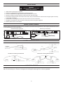
COVERAGE PATTERN
Density and range of the coverage pattern is determined by mounting height. The FS-205 has a multi-cell, multi-tier Fresnel lens with a
view of 360°. This lens is designed to detect small motion when mounted within 6' of occupants. Coverage shown in the diagrams below
is maximum. They represent full-step walking motion, with no barriers or obstacles. When mounted at a height of 8', the coverage area
is approximately 14' diameter.
(0m) (0.8m)
0ft 2.5'
(1.5m)
5'
5'
(1.5m)
7.5'
(2.3m)
0ft
(0m)
5'
(1.5m)
7.5'
(2.3m)
(2.3m)
7.5'
(1.5m)
5'
(2.3m)
7.5'
(0.8m)
2.5'
2.5'
(0.8m)
2.5'
(0.8m)
5'
(1.5m)
8'
(2.4m)
0ft
(0m)
(0m) (0.8m)
0ft 2.5'
(1.5m)
5'
(2.3m)
7.5'
(1.5m)
5'
(2.3m)
7.5'
(0.8m)
2.5'
2.5'
(0.8m)
FS-205 coverage pattern, top view
FS-205 coverage pattern, side view
The power supply for the FS-205 is a FS-PP power pack mounted inside a light fixture. Each WattStopper FS-PP power pack can
supply power for up to ten FS-205 sensors.
The sensor is equipped with a 6’ long cable fitted with a male RJ45 plug. The FS-PP has a corresponding female RJ45 receptacle. This
cable carries power to the sensor and the 24VDC maintained output to the power pack to signal that lights should be on.
Important: There is an initial warm-up period external load to the sensor.
It may take up to a minute for the sensor to warm-up during the initial power-up. The sensor has an “instant on” feature. This occurs
during installation or after a lengthy power failure only. As soon as power is supplied, the lights will come ON and stay ON for
approximately 1 minute. If no movement is detected within that time the lights will turn OFF until detection occurs. If movement is
detected during the initial 1 minute then the lights will stay ON for whatever time has been set on the time delay.

2
INSTALLATION
1. 24VDC class 2 power supply is required.
2. Determine an appropriate mounting location inside the light fixture.
3. Cut a 3/4 “ diameter hole through the sheet metal in the bottom of the fixture.
4. Remove the beauty ring and thumbscrew collar from the FS-205-LE lens pipe.
5. Insert the lens through the hole in the bottom of the fixture; then put the thumbscrew collar onto the lens pipe. Tighten it securely
to the outside of the fixture.
6. Use the holes or mounting slots at both ends of the sensor to secure it to the fixture.
7. Re-tighten the thumbscrew collar, then put the beauty ring onto the lens pipe and tighten it.
8. Restore power from the circuit breaker.
WARNING:
TURN THE POWER OFF AT THE CIRCUIT
BREAKER BEFORE WIRING.
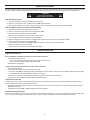
WIRING A SINGLE SENSOR
All power wiring goes through the FS-PP. The only connection to the FS-505 is through the RJ45. The Occupancy Mode Switch should
be set to ON for these wiring configurations.
Com
N/O
RJ45
Plug
from FS
sensor
Line
120/277/347 Volts AC
Neutral
Ground
Green Operation
LED
COM
N/O
N/C
03500r1
ISOLATED RELAY
OUTPUTS
TO LOAD
RJ45
TO SENSOR
Lighting
Load
Neutral
FS-PP V2
Model:
Fixture Sensor Power Pack
120/277/347VAC, 60Hz
@120VAC 5A (N/O)
3A (N/C)
@277VAC 4.3A (N/O)
2.5A (N/C)
@347VAC 3.4A (N/O)
2A (N/C)
GROUND
NEUTRAL
LINE
03392r2
Strip Gauge
12-18AWG
CU wire only
88T9
Appliance
Control
LISTED
AC INPUT
www.legrand.us
800.879.8585
N/C
Grey
Com
Violet
0-10VDC
0-10VDC
Dimming Ballast
Line Voltage
Inputs to
Ballast
Outputs
to Lamps
Line
120/277/347 Volts AC
Neutral
Ground
Green Operation
LED
COM
N/O
N/C
03500r1
ISOLATED RELAY
OUTPUTS
TO LOAD
RJ45
TO SENSOR
RJ45
Plug
from FS
sensor
FS-PP V2
Model:
Fixture Sensor Power Pack
120/277/347VAC, 60Hz
@120VAC 5A (N/O)
3A (N/C)
@277VAC 4.3A (N/O)
2.5A (N/C)
@347VAC 3.4A (N/O)
2A (N/C)
GROUND
NEUTRAL
LINE
03392r2
Strip Gauge
12-18AWG
CU wire only
88T9
Appliance
Control
LISTED
AC INPUT
www.legrand.us
800.879.8585
FS-PP direct wiring to lighting load
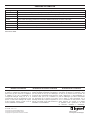
CONTROL CONFIGURATIONS
Any 24DC
FS Sensor
FS-PP
One Sensor controlling one Power Pack
Any 24 DC
FS Sensor
FS-PP
FS-PP
FS-C4
FS-C3 (3”)
or
FS-C!1 (10’)
One Sensor controlling two Power Packs
Any 24VDC
FS Sensor
Any 24VDC
FS Sensor
FS-PP
FS-C4
FS-C3 (3”)
or
FS-C1 (10”
Two Sensors controlling one Power Pack
Any 24VDC
FS Sensor
Any 24VDC
FS Sensor
FS-PPFS-PP
FS-C4 FS-C4
FS-C3 (3”)
or
FS-C1 (10’)
Two Sensors controlling two Power Packs
FS-PP wiring to control ballast
LIGHT LEVEL FEATURE
The Light Level feature holds lights OFF upon initial occupancy if adequate ambient light exists. It will not turn the lights OFF if they are
ON. The default setting is for maximum, meaning that even the brightest ambient light will not hold the lights OFF.

3
SENSOR ADJUSTMENT
The Time Delay and Light Level adjustment potentiometers are on the top of the FS-205 body. It may be necessary to adjust the sensor
before the fixture is fully assembled. Adjust the light level setting during daylight hours when ambient light is at the desired level.
Test Occupancy Sensor
1. Turn the time delay to minimum and light level to maximum.
2. Move out of the sensor’s view. Lights should turn OFF after 30 seconds.
3. Move into the detection area. The red LED in the sensor lens should illuminate and the lights should turn ON.
Test and Adjust Light Level Sensor and Time Delay
1. Adjust the light level and the time delay to minimum.
2. Leave the area and let the sensor time out so lights are OFF.
3. Enter the space, and lights should remain OFF.
Make sure your body does not cast a shadow on the sensor.
4. Turn the light level trimpot clockwise in small increments.
5. After each adjustment, move about the coverage area and wait 5-10 seconds to see if the lights turn ON.
6. Continue this procedure until the lights turn ON.
At this setting, the lights will not turn ON if light levels are above the current natural illumination.
7. Set the time delay to the desired setting.
The time delay can be set from 30 seconds to 30 minutes.
TROUBLESHOOTING
Lights will not turn on:
Sensor LED does not ash when motion is within 6 feet of detector:
• Is green power pack LED on?
▸ If yes, check all RJ45 connections between sensors and power pack.
▸ If no, check circuit breaker and wiring to power pack.
• Check all wire connections
•Sensor LED does ash when motion is within 6 feet of detector:
• Check light level setting.
• Cover the sensor lens to simulate darkness in the room.
If the lights come ON, the light level needs to be adjusted. If set for minimum, more than 10fc of ambient light will cause the lights
to be held OFF. See Sensor Adjustment section for instructions.
• Check all wire connections and verify the load wires are tightly secured at the power supply.
• If lights still do not turn ON, call 800.879.8585 for technical support.
Lights will not turn off:
The time delay can be set from 30 seconds to 30 minutes. Ensure that the time delay is set to the desired delay and that there is no
movement within the sensor’s view for that time period.
• To quickly test the unit for proper operation, turn the time delay to minimum and move out of the sensor’s view. Lights should turn
OFF after 30 seconds.
• If lights still do not turn OFF, call 800.879.8585 for technical support.
Operation During Power-Up
During the sensor warm-up period, which can last up to a minute after initial power-up (or after a lengthy power outage), the load will be
on for 1 minute. After warm-up, the sensor will open or close the relay to correspond to the occupancy status of the room.
CAUTION
DO NOT OVERTURN TRIMPOT
WHEN ADJUSTING THE SENSOR!

800.879.8585
www.legrand.us/wattstopper
No. 25788 – 07/17 rev. 1
© Copyright 2016 Legrand All Rights Reserved.
© Copyright 2016 Tous droits réservés Legrand.
© Copyright 2016 Legrand Todos los derechos reservados.
Wattstopper warranties its products to be free
of defects in materials and workmanship for a
period of five (5) years. There are no obligations
or liabilities on the part of Wattstopper for
consequential damages arising out of, or in
connection with, the use or performance of this
product or other indirect damages with respect
to loss of property, revenue or profit, or cost of
removal, installation or reinstallation.
Wattstopper garantit que ses produits sont
exempts de défauts de matériaux et de fabrication
pour une période de cinq (5) ans. Wattstopper
ne peut être tenu responsable de tout dommage
consécutif causé par ou lié à l’utilisation ou
à la performance de ce produit ou tout autre
dommage indirect lié à la perte de propriété, de
revenus, ou de profits, ou aux coûts d’enlèvement,
d’installation ou de réinstallation.
Wattstopper garantiza que sus productos
están libres de defectos en materiales y mano
de obra por un período de cinco (5) años. No
existen obligaciones ni responsabilidades por
parte de Wattstopper por daños consecuentes
que se deriven o estén relacionados con el
uso o el rendimiento de este producto u otros
daños indirectos con respecto a la pérdida
de propiedad, renta o ganancias, o al costo
de extracción, instalación o reinstalación.
WARRANTY INFORMATION INFORMATIONS RELATIVES À LA GARANTIE INFORMACIÓN DE LA GARANTÍA
ORDERING INFORMATION
Catalog Number Description
FS-205 v2 Fixture mount, low voltage PIR occupancy sensor, adjustable time delay and light level
FS-PP Fixture Mount Power Pack, 120-277VAC, 60Hz with No/NC Relay output
FS-C1 One 10’ cable with a shieldes RJ45 male connector at each end.
FS-C2 One 6’ cable with e flying leads at one end and a shielded RJ45 male connector at the other.
FS-C3 One 3’ cable with a shielded 90o RJ45 male connector and a shielded straight male RJ45 connector.
FS-C4 Shielded RJ45 splitter with female to dual female receptacles.
FS-C5 Shielded RJ45 male-to-male couple.
FS-CK-2 RJ45 to 3-wire connection kit.
Sensors are White.
-
 1
1
-
 2
2
-
 3
3
-
 4
4


Legrand FS-205 Low Voltage PIR Fixture Integrated Occupancy Sensor Mode d'emploi
- Catégorie
- Détecteurs de mouvement
- Taper
- Mode d'emploi
- Ce manuel convient également à
dans d''autres langues
Documents connexes
-
wattstopper C-Series Guide d'installation
-
-
wattstopper A277C-P Guide d'installation
-
-
Legrand FS-305 Low Voltage Occupancy and Light Level Sensor Guide d'installation
-
-
-
-
-