MicroNet SP3352 Manuel utilisateur
- Catégorie
- Les routeurs
- Taper
- Manuel utilisateur

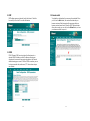
Installation Guide
Broadband ADSL Router
Model No. SP3352
http://www.micronet.info
1
CE Declaration of conformity
This equipment complies with the requirements relating to
electromagnetic compatibility, EN55022 class A for ITE, the essential
protection requirement of Council Directive 89/336/EEC on the
approximation of the laws of the Member States relating to
electromagnetic compatibility.
FCC Part 68
This equipment complies with Part 68 of the FCC Rules. On the
bottom of this equipment is a label that contains the FCC Registration
Number and Ringer Equivalence Number (REN) for this equipment.
You must provide this information to the telephone company upon
request.
The REN is useful to determine the quantity of devices you may
connect to the telephone line and still have all of those devices ring
when your number is called. In most, but not all areas, the sum of the
REN of all devices connected to one line should not exceed five (5.0).
To be certain of the number of devices you may connect to your line,
as determined by the REN, you should contact your local telephone
company to determine the maximum REN for your calling area.
If the modem causes harm to the telephone network, the telephone
company may discontinue your service temporarily. If possible, they
will notify you in advance. But if advance notice isn't practical, you will
be notified as soon as possible. You will be advised of your right to file
a complaint with the FCC.
The telephone company may make changes in its facilities,
equipment, operations, or procedures that could affect the proper
operation of your equipment. If they do, you will be notified in
advance to give you an opportunity to maintain uninterrupted
telephone service.
If you experience trouble with this modem, please contact your dealer
for repair/warranty information. The telephone company may ask you
to disconnect this equipment from the network until the problem has

2
been corrected or you are sure that the equipment is not
malfunctioning.
This equipment may not be used on coin service provided by the
telephone company. Connection to party lines is subject to state tariffs.
Installation
This device is equipped with a USOC RJ11C connector.
FCC Part 15
The modem generates and uses radio frequency energy. If it is not
installed and used properly in strict accordance with the user's
manual, it may cause interference with radio and television reception.
The modem has been tested and found to comply with the limits for
Class B computing devices in accordance with the specifications in
Subpart B, Part 15 of the FCC regulations. These specifications are
designed to provide reasonable protection against such interference
in a residential installation. However, there is no guarantee that
interference will not occur in a particular installation. FCC regulations
require that shielded interface cables be used with your modem.
If interference does occur, we suggest the following measures be
taken to rectify the problem:
1) Move the receiving antenna.
2) Move the modem away from the radio or TV.
3) Plug the modem into a different electrical outlet.
4) Discuss the problem with a qualified radio / TV technician.
CAUTION:
Changes or modifications not expressly approved by the party
responsible for compliance to the FCC Rules could void the user's
authority to operate this equipment.
Cable connections:
All equipment connected to this modem must use shielded cable as
3
the interconnection means.
Notes:
Operation is subject to the following two conditions:
1) This device may not cause harmful interference, and
2) This device must accept any interference received including
interference that may cause undesired operation.

4
Table of Contents
CE Declaration of conformity.............................................................................1
Chapter 1 Introduction......................................................................................6
1.1 Overview ..................................................................................................6
1.2 Features ...................................................................................................6
1.3 System Requirements.........................................................................9
Chapter 2 Installation..................................................................................... 10
2.1 Checklist................................................................................................ 10
2.2 The Front LEDs....................................................................................11
2.3 The Rear Ports.................................................................................... 12
2.4 Hardware installation ........................................................................ 13
Chapter 3 Joint ADSL Router to the network......................................... 17
3.1 Purpose.................................................................................................17
3.2 Determine your connection settings ............................................ 17
3.3 Connecting the ADSL Router to your network......................... 18
3.4 The relative configuration on your computers.......................... 19
Chapter 4 Configuring with Web Browser............................................... 22
4.1 Open the Web Management Interface........................................ 22
4.2 Setup the Router................................................................................ 23
4.3 Basic Configuration........................................................................... 27
4.3 Advanced Configuration................................................................... 36
4.4 Utility....................................................................................................... 37
5
4.5 Monitor................................................................................................... 40
4.6 Help......................................................................................................... 44
Chapter 5 Configuring with Console Port................................................ 45
5.1 Install system via console port:..................................................... 45
5.5 Example of RFC1483 Routed mode:.......................................... 48
5.6 Example of RFC1483 Bridged mode: ......................................... 53
5.7 Example of RFC2516 (PPPoE) plus NAT mode: .................... 54
5.8 Example of RFC2364 (PPPoA) plus NAT mode: .................... 56
Chapter 6 Troubleshooting........................................................................... 58
Chapter 7 Frequently Asked Questions ................................................... 64
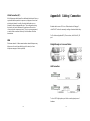
Appendix A Glossary...................................................................................... 69
Appendix B Cabling / Connection .............................................................. 79
Appendix C Service / Port ............................................................................ 80

6
Chapter 1
Introduction
Congratulations on your purchase of the ADSL Router. This router
provides high performance, complete telecommunications and
networking solutions for your home or branch office.
This chapter provides an overview of the asymmetric digital
subscriber line (ADSL) Discrete Multi-Tone (DMT) router. It also
describes the general applications available with the ADSL Router.
1.1 Overview
The ADSL Router provides home connectivity to an ADSL service
provider network over an ADSL/Asynchronous Transfer Mode (ATM)
physical layer. The router can run upstream maximum transmission
rates of 640Kbps and downstream maximum transmission rates of
8Mbps. The actual rate depends on the copper category of your
telephone wire, distance from the central office and the type of ADSL
service subscribed. A four ports switching hub of the ADSL Router is
provided for connection to an Ethernet LAN or Ethernet-equipped PC,
and this router is easy to install and to configure.
1.2 Features
ADSL Features
Ÿ Compatible with all leading DSLAMs
Ÿ Supports DMT line modulation
Ÿ Supports Full-Rate ADSL: up to 8Mbps downstream, up to 1Mbps
upstream
Ÿ ANSI T1.413 Issue 2, ITU-T G.992.1 (G.dmt) Annex A compliant
for ADSL over POTS - optioin
7
Ÿ ITU-T G.992.1 (G.dmt) Annex B/ETSI TS 101 388 / DTS TM-06006
for ADSL over ISDN (ETSI)-option
Ÿ ITU-T G.992.1 Annex B - Deutsch Telecom for ADSL over ISDN
(U-R2) - option
Ÿ Supports G.Lite ADSL: up to 1.5Mbps downstream, up to 512Kbps
upstream (G.992.2)
Ÿ Supports DSL handshaking (G.994.1)
ATM Features
Ÿ RFC1483 Encapsulation (LLC & VC multiplexing) (IP, Bridging &
encapsulated routing)
Ÿ PPP over ATM (RFC2364)
Ÿ Classical IP (RFC1577)
Ÿ Traffic shaping (UBR)
Ÿ PPP over Ethernet client (RFC2516)
Management Features
Ÿ Local & Remote Management
Ÿ HTML browser Interface
Ÿ Telnet and RS-232D console configuration
Ÿ Command Line Interface
Ÿ Firmware upload/download via TFTP of LAN or XMODEM of
console port
Ÿ Alarm Status & Power Indicators
Ÿ Event & History logging (Option)
Ÿ Network Ping
Ÿ Simple Network Management Protocol(SNMP) Management
Information Base (MIB) support (Option)

8
Application Features
Ÿ Supports IEEE 802.1d transparent learning bridging, IP routing,
Ÿ Support PAT (Port address translation) and NAT (Network address
translation)-This allows multiple users to access the LAN
simultaneously using a single IP address
Ÿ DHCP server
Ÿ NAT and PAT
Ÿ Ping
Ÿ Telnet server
Ÿ TFTP client
Ÿ Web server (HTTP server)
Internet Protocol (RFC791)
Ÿ User Datagram Protocol (RFC 768)
Ÿ Internet Control Message Protocol (RFC 792)
Ÿ Ethernet Address Resolution Protocol (RFC 826)
Ÿ RIP version 1 and RIP version 2 updating of routing tables
Physical Interfaces
Ÿ ADSL Modem/Router with four RJ-45 10/100 Ethernet port, & an
ADSL port
Ÿ WAN Status & Power LED indicators
Minimum System Requirements
Ÿ Any computer with an Ethernet 10 Base-T interface
Ÿ Any operating system that supports an Ethernet Connection with
an IP stack
9
Security Features
Ÿ Password protected configuration access
Ÿ User authentication (PAP/CHAP) The router supports PAP
(Password Authentication Protocol) and CHAP (Challenge
Handshake Authentication Protocol)
Ÿ Firewall
Ÿ NAT
Ÿ NAPT
Ÿ LAN Features
Ÿ DHCP server - DHCP allows you to assign dynamically and
automatically
Ÿ IP address settings to hosts on your network.
Ÿ IP Multicast (option)
Routing Features
Ÿ TCP/IP with RIP v2
Ÿ Static Routing
1.3 System Requirements
1) A PC that has a standard terminal emulation program with VT-100
or a dumb terminal come with a DB-9 serial port
2) A computer system with a Ethernet port

10
Chapter 2
Installation
This chapter offers information about installing your router. If you are
not familiar with the hardware or software parameters presented here,
please consult your service provider for the values needed.
2.1 Checklist
Check the shipping box carefully to ensure that the contents include
the items you ordered. If any of the items are missing or damaged,
contact your local distributor. The contents of your carton may vary
depending on your service provider.
Contents description
1) ADSL Router for home/office use.
2) ADSL Router Installation and Operation Guide (this publication)
3) Power supply with 9Vdc / 1.5 Ampere power adapter
4) ADSL cable RJ-11 telephone cable (6 ft)
5) Ethernet cable Ethernet category 5 Straight-through cable (6 ft)
6) RS-232D cable (DB9 female to DB9 male cable)
11
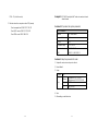
2.2 The Front LEDs
LED Description
Power Power is applied to the Router
DWG
ADSL physical layer with uncorrected blocks if
LED is flash
LINK
ADSL connection has been established if LED is
on
WAN
OP
Router works properly with flashing LED
LAN(1-4): These four LAN (Local Area Network) ports are where
you will connect networked devices, such as PCs, print servers,
remote hard drives, and anything else you want to put on your
network.

12
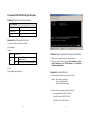
2.3 The Rear Ports
Connector Description
POWER Power connector with 9Vdc/ 1 .5 Ampere
Consol Port
(RS232)
Connects to the serial port on your PC or laptop with
DB-0 serial port (default value - 115200 bps/data
bits 8/parity none/ stop bit 1/ flow control disabled)
Ethernet
Port (RJ-45)
Connects to the Ethernet port
ADSL
Connector
(RJ-11)
Connects to the wall jack
13
2.4 Hardware installation
This section describes how to connect and configure the ADSL router.
1. Management via Ethernet Interface
Step 1. Connect the ADSL Line
Connect the router directly to the wall jack using the included
ADSL cable.
Step 2. Connect a Workstation to the Router's LAN port
There are two methods to connect the router and workstation.
The one use cable to connect directly between them. The
other use Ethernet cable to connect router with hub (or
switch), then go to the workstation.
Step 3. Connect the Power Adapter to the Router
Connect the power adapter to the port labeled POWER on
the rear panel of router.
Step 4. Connect All Cables to the Network
The procedure for connecting cables differs depending on
whether or not your telephone equipment is connected to a
POTS splitter.

14
2. Management via Console Port
Step 1. Connect the Console Port to the Serial Port
For the first configuration of this router, you need to use
terminal emulator software on a workstation and connect it to
the router through the console port. Connect the 9-pin end of
the console cable (9-pin to 9-pin console cable supplied) to
the console port of the router and the 9-pin end to a serial port
(COM1, COM2 or other COM port) of your workstation.
Step 2. Configure the Serial Port
For the best access to the router, use your terminal emulation
program (such as HyperTerminal in Windows) to set your
COM protocol to the following settings:
Baud rate: 115200 bps
Data bits: 8
Parity: None
Stop bits: 1
Flow control: None
Step 3. Connect All Cables to the Network
The procedure for connecting cables differs depending on
whether or not your telephone equipment is connected to a
POTS splitter.
15
POTS Splitter Configuration (ADSL over POTS)
A POTS splitter separates data signals from voice signals on your
telephone line. The POTS splitter works by running a separate data
line from the voice line, so that the ADSL router has a dedicated cable
for data transmission. Hereunder s hows the connection of all cables
to the Router.
Note: The POTS splitter may also be installed on the outside of the
house adjacent to the telephone network interface device (NID).

16
ISDN Splitter Configuration (ADSL over ISDN)
A ISDN splitter separates ADSL signals from ISDN signals on your
ISDN telephone line. The ISDN splitter works by running a separate
ADSL line from the ISDN line, so that the ADSL router has a
dedicated cable for data transmission. Figure shows how to connect
all cables to the Router.
Note: The ISDN splitter may also be installed on the outside of the
house adjacent to the telephone network interface device (NID).
17
Chapter 3
Joint ADSL Router to the network
3.1 Purpose
This chapter provides information about configuring the ADSL Router.
3.2 Determine your connection settings
Before you configure the router, you need to know the connection
information supplied by your ADSL service provider.
Protocol Selection
RFC1483 -> Bridged Ethernet over ATM or Routed IP over ATM
RFC2364 -> Point-to-Point Protocol over ATM
RFC2516 -> Point-to-Point Protocol over Ethernet
VPI value:
VCI value:
Framing: VcMUX LLC / SNAP
For RFC1483 For R FC2364 or 2516
Host: User Name:
Domain: Password:
Gateway: Host or IP Address:
IP Address:
Subnet Mask:
DNS or server address:

18
3.3 Connecting the ADSL Router to your network
Unlike a simple hub or switch, the setup of the ADSL Router consists
of more than simply plugging everything together. Because the
Router acts as a DHCP server, you will have to set some values
within the Router, and also configure your networked PCs to accept
the IP Addresses the Router chooses to assign them. Generally there
are several different operating modes for your applications. And you
can know which mode is necessary for your system from ISP. These
modes are router, bridge, PPPoE+NAT and NAT and PPPoA+NAT.
Actually all these are for IP address of WAN.
1. If your ISP provides RFC1483 Routed mode, it means the IP
address of LAN will be routed via WAN.
You should set the "Router" mode in the ADSL router for this
situation, also set the IP address / netmask of LAN and VPI/VCI
of WAN. Then save and reboot Router, it will work fine with your
whole system. The computer should be set the fixed assigned IP
address with the same domain at this mode.
2. If your ISP provides RFC1483 Bridge mode plus PPPoE, it
means the IP address of computer or router will be assigned
automatically via PPPoE.
There are two methods you can use at this mode. First you can
set the "bridge" mode, give VPI/VCI of WAN and install PPPoE
driver on your computer. Then save and reboot router, it will work
fine with your whole system. You need to use D ial_Up_Network
to get the IP address of computer every time.
Second method you can set the "PPPoE+NAT" mode, give
VPI/VCI of WAN and set user's name & password for PPPoE on
your router. Then save and reboot router, it will work fine with
your whole system. The computers should be set as DHCP client
to get IP dynamically.
3. If your ISP provides RFC2364 mode, it means the IP address of
router will be assigned automatically via PPPoA.
You can set the "PPPoA+NAT" mode, give VPI/VCI of WAN and
set user's name & password for PPPoA on your router. Then save
19
and reboot router, it will work fine with your whole system. The
computers should be set as DHCP client to get IP dynamically.
4. If your ISP provides RFC1483 Routed and the serial static IP
address for you, there are two methods you can use at this mode.
First you can set the "router" mode and give VPI/VCI of WAN.
Then save and reboot router, it will work fine with your whole
system. The computers should be set the fixed assigned IP
address at this method.
Second method you can set the "NAT" mode, give VPI/VCI/ IP
address /netmask of WAN. Then save and reboot router, it will
work fine with your whole system. The computers should be set
as DHCP client to get IP dynamically.
3.4 The relative configuration on your computers
Please follow the steps to install your system via web server at first
time:
1. Power everything down, including your PCs, and ADSL Router.
2. Connect a crossover network cable from one of your PCs' Ethernet
ports to the LAN port on the back of the Router or connect a
straight network cable from hub (or switch) to the LAN port on the
back of the Router.
3. Connect the power-adaptor to the Power port on the rear of the
Router, then connect to a power outlet using the power cord
included in the Router's packaging.
4. Power on one of your PCs and login if you are asked to. When you
reach the desktop, click the Start button, select Settings, and then
select Control Panel.
5. Double-click the Network icon.
6. In the Configuration window, highlight the TCP/IP that has been
associated with your network card or adapter. (Do NOT configure
TCP/IP->Dial-up Adapter.) Click Properties. If the TCP/IP
Protocol isn't listed in the Configuration window, try to install it.

20
7. Click the IP Address tab. Select Obtain an IP address
automatically. Click OK.
21
8. Click OK again. Windows may begin copying files to your computer,
and then ask you to restart your PC. Click Yes to restart your
computer and initiate the new settings. If you aren't asked,
manually restart the computer.

22
Chapter 4
Configuring with Web Browser
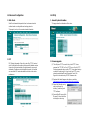
4.1 Open the Web Management Interface
Open the web browser, enter the local port IP address of the ADSL
Modem/Router, which default at http://192.168.8.1, and click 'Go' to
get the management page.
23
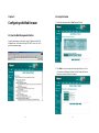
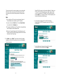
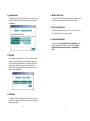
4.2 Setup the Router
1. Select the operating mode in Step 1 page as follows.
2. Click Next then the next required setup page will pop up. If the
Rouer works as Bridge mode then the Host Name and Domain
Name box should not show in this page.

24
These values refer to the internal network you are creating with
this Router. Unless you have specific internal needs or in the
router mode, there should be no requirement to change these
values.
Note:
(1) Check with your ISP to see if you need to enter Router &
Domain Names to be viewed by your ISP's network.
(2) If you do, click on the Start button. Choose Control Panel,
then double-click the Network icon.
(3) Choose the Identification tab. There will be a Computer Name
and a Workgroup name displayed here.
(4) Enter the Computer Name into the Router Name box on the
Setup Page, and enter the Workgroup name into the Domain
Name box on the Setup Page.
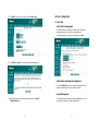
3. Click Next box go to Step 3. These values refer to the outside
network you connect to every time you access your Broadband
Internet connection.
25
Most ADSL ISPs assign their clients with a different IP address via
PPPoE or PPPoA each time they log on. If this is the case with
your ISP, you should set PPPoE+NAT or PPPoA+NAT mode at
previous Step 1. You can setup PPPoE or PPPoA activity time, the
router will log off when the idle time up.
6. You should check with your ISP for VPI/VCI and AAL5
Encapsulation for ATM VC parameter if you select PPPoE or
PPPoA mode.
7. You should give user's name and password if you select
PPPoE+NAT or PPPoA+NAT mode in Step 1 .

26
8. Click Next then you can see all the values in Step 6 page.
9. Click Finish then Save. The device will restart automatically.
10. After Router reboots, the web browser will back to the Quick
Setup Wizard page.
27
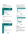
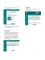
4.3 Basic Configuration
1. User Profile
User Profile for management
This Router allows you setting User name and Password to
prevent improper accessing from un-allowed users.
The default setting of user name and password are adsl.
Authorization requirement for management
Check the Enable radio box then system will request the user
name and password when any accessing requests.
Remote Management
This Router allows three types of remote management. You can
check the radio box(es) to enable the feature(s).

28
2. Log table display setting
The pack log setting allows the display of the incoming and
outgoing data on the monitor. It helps you understanding the traffic
over this ADSL Router.
Check the box to enable the function then you can find the record
on Monitor section .
3. Packet filter
Packet filter is a firewall facility that analyzes incoming data
packets and forwards them or discards them based on one or more
criteria such as address, range of addresses and type (e-mail, file
transfer, etc.).
29
You can add the IP address, IP range, Port range or Mac address
of the local PC to access the Internet or URL keywards.
Click LAN to WAN, t he three items will show below. Click the item
you need then the table will show and let you key in the data.
Click WAN to LAN, you can fill in the IP address to make sure they
can’t access to the local PCs from Internet.
Configure MTU Setting
MTU (Maximum Transmission Unit) is the largest frame size that
can be transmitted over the network. Messages longer than the
MTU must be divided into smaller frames.
For most DSL users, it is recommended to use 1492. It is
recommended that you should keep this value at the range of 1200
to 1500. The default setting is set at 1500 to compatible most
situations.

30
4. User Access Control
This page is used to manage permissions for logging on to a
computer or network. You can fill in the LAN IP address (MAC
Address) and port range rule to limit the network attribution of the
local user.
31
5. DHCP
DHCP (Dynamic Host Configuration Protocol) lets client stations
get IP addresses whenever logging onto a TCP/IP network
automatically. It saves the effort to assign permanent IP addresses
in each client PC manually.
You can define some host having fixed IP. Key in the host MAC ID
and map to a fixed IP address.

32
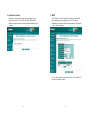
6. Forwarding
The feature allows Internet users to communicating directly with a
computer that resides inside a firewall using Network Address
Translation (NAT) to hide the identity of internal machines from the
outside world.
Virtual Server has the highest priority, port forwarding is secondary.
Port triggering is used to deal with application protocols that create
separate sessions so it is less priority.
If there are some applications on your network the highest priority
application will get the port(s) for communication and the others
will be disconnected and reconnected until the highest one
releasing the port(s).
33
7. Multiple NAT and Multiple DMZ
Multiple NAT
NAT (Network Address Translation), it allows an organization to
present itself to the Internet with one address. NAT converts the
address of each LAN node into one IP address for the Internet and
vice versa. It also serves as a native firewall by keeping individual
IP address hidden from the outside world.
This deivce provides grouping local IP range access Internet via
more than one WAN IP.
Multiple DMZ
DMZ (DeMilitarized Zone) is a middle ground between an
organization's trusted , internal network and an untrusted, external
network such as the Internet. The DMZ is a subnetwork (subnet)
that may sit between firewalls or off one leg of a firewall.
You can set more than one DMZ host in this DMZ parameter to
expose host/server to the Internet.
When the DMZ host is mapped to a W AN IP, please enable the
local host as DMZ host in the DMZ page simultaneously.

34
8. DMZ
DMZ setting exposes an internal host to the Internet. Check the
box and key in the host IP to enable this feature.
9. DDNS
DDNS (Dynamic DNS) service points a fixed hostname to a
dynamic WAN IP address or static IP address, allowing your
computer to be accessed from various locations on the Internet
without knowing your current IP. With a DDNS connection you can
host your own web site, email server, FTP site and more at your
own location.
35
10. Save & restart
To update the configuration, the server must be restarted. When
you click on the Save button, the router will restart and your
browser session will be disconnected.It may appear that your
browser session doesn't work. When the ADSL Router restarts
after a few seconds, you can click on the Reload button, or close
your browser and then re-open it.

36
4.3 Advanced Configuration
1. Static Route
Static Route forwards data packets from local area network to
another based on routing tables and routing protocols.
This page let you key in the remote network information.
2. RIP
RIP (Routing Information Protocol) is part of the TCP/IP protocol
suite. It indicates that the path used to pass traffic between routers
is based on the fewest number of hops between the source and
destination IP addresses included within the packet. It should be
concerned that RIP wastes bandwidth and reduces the router’s
performance.
37
4.4 Utility
1. General System Information
This page shows the information of this router.
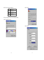
2. Firmware upgrade
(1) This utility need TFTP server for help. Install TFTP Server
program, like TFTPD32 or Cisco TFTP Server. Run the TFTP
Server program and make sure the TFTP Server base directory
contains the codes.img file. If you do not have TFTP server,
please download from Micronet Download Center. The
HyperLink is located near by SP3352 firmware code.
(2) Download the latest firmware code from our web site.
http://www.micronet.info/Download/driver/driver.asp#adsl
(3) Extract the file before using
and check the zip file
including “codes.img” and
TFTP software.
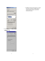
(4) Execute tftpd32.exe and click
“Browse” to select the folder
including the codes.img.

38
(5) Key in the server’s IP as TFTP Server IP Address i.e. your
computer’s IP address.
(6) Click OK to execute firmware upgrade process.
(7) The process will be finished in one minute and the IP will be
reset to default value, 192.168.8.1.
3. Load Default Setting
This page allows you to load the factory default settings. When you
click on the OK box, your ADSL Router will load the default
settings and restart. When the ADSL Router is restarted, your
browser session will be disconnected.It may appear that your
browser session doesn't work. When the ADSL Router restarts
after a few seconds, you can click on the Reload button, or close
your browser and then re-open it.
39
4. Save & restart
Press Save box to save the configuration when ever the setting
has been changed.
La page charge ...
La page charge ...
La page charge ...
La page charge ...
La page charge ...
La page charge ...
La page charge ...
La page charge ...
La page charge ...
La page charge ...
La page charge ...
La page charge ...
La page charge ...
La page charge ...
La page charge ...
La page charge ...
La page charge ...
La page charge ...
La page charge ...
La page charge ...
La page charge ...
-
 1
1
-
 2
2
-
 3
3
-
 4
4
-
 5
5
-
 6
6
-
 7
7
-
 8
8
-
 9
9
-
 10
10
-
 11
11
-
 12
12
-
 13
13
-
 14
14
-
 15
15
-
 16
16
-
 17
17
-
 18
18
-
 19
19
-
 20
20
-
 21
21
-
 22
22
-
 23
23
-
 24
24
-
 25
25
-
 26
26
-
 27
27
-
 28
28
-
 29
29
-
 30
30
-
 31
31
-
 32
32
-
 33
33
-
 34
34
-
 35
35
-
 36
36
-
 37
37
-
 38
38
-
 39
39
-
 40
40
-
 41
41


MicroNet SP3352 Manuel utilisateur
- Catégorie
- Les routeurs
- Taper
- Manuel utilisateur
dans d''autres langues
- English: MicroNet SP3352 User manual
Autres documents
-
Bluestork BS-WG-RT4MD Le manuel du propriétaire
-
Linksys X2000X3000X3500 Le manuel du propriétaire
-
Atlantis A02-RAV211 Mode d'emploi
-
Atlantis A02-RA111 Manuel utilisateur
-
-
-
Hama 00062727 Le manuel du propriétaire
-
Belkin F5D9630-4 Manuel utilisateur
-
-