
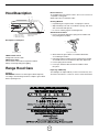
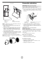
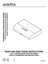
Installation Instructions Guide
Guía de Instrucciones para Instalación
Guide d’instructions d’installation
READ AND SAVE THESE INSTRUCTIONS
LEA Y GUARDE ESTAS INSTRUCCIONES
LIRE ET CONSERVER CES INSTRUCTIONS
LIB0119775
English page 2
Español página 11
Français page 20

2
Table of Contents
Important Safety Notice........................................................ 2
Tools and Parts...................................................................... 3
Dimensions and Clearances................................................. 3
Electrical Requirements........................................................ 4
Venting Requirements........................................................... 4
Venting Methods.................................................................... 4
Installation Instructions......................................................... 5
Electrical Connection............................................................ 8
Hood Description................................................................... 9
Range Hood Care................................................................... 9
Warranty.................................................................................. 10
APPROVED FOR RESIDENTIAL APPLIANCES
FOR RESIDENTIAL USE ONLY
READ AND SAVE THESE INSTRUCTIONS
PLEASE READ ENTIRE INSTRUCTIONS BEFORE PROCEEDING.
INSTALLATION MUST COMPLY WITH ALL LOCAL CODES.
IMPORTANT: Save these Instructions for the Local Electrical
Inspector’s use.
INSTALLER: Please leave these Instructions with this unit for
the owner.
OWNER: Please retain these instructions for future
reference.
Safety Warning:Turn off power circuit at service panel and lock
out panel before wiring this appliance.
Requirement 120 VAC, 60 Hz. 15 or 20 A Branch Circuit
IMPORTANT SAFETY INSTRUCTIONS
WARNING: TO REDUCE THE RISK OF FIRE, ELECTRIC
SHOCK, OR INJURY TO PERSONS, OBSERVE THE
FOLLOWING:
■ Use this unit only in the manner intended by the
manufacturer. If you have questions, contact the
manufacturer.
■ Before servicing or cleaning the unit, switch power off at
service panel and lock the service disconnecting means to
prevent power from being switched on accidentally. When
the service disconnecting means cannot be locked, securely
fasten a prominent warning device, such as a tag to the
service panel.
■ Installation work and electrical wiring must be done by
qualied person(s) in accordance with all applicable codes
and standards, including re-rated construction.
■ Sufcient air is needed for proper combustion and
exhausting of gases through the ue (chimney) of fuel
burning equipment to prevent backdrafting. Follow the
heating equipment manufacturer’s guideline and safety
standards such as those published by the National Fire
Protection Association (NFPA), the American Society for
Heating, Refrigeration and Air Conditioning Engineers
(ASHRAE), and the local code authorities.
■ When cutting or drilling into wall or ceiling; do not damage
electrical wiring and other hidden utilities.
■ Ducted fans must always be vented outdoors.
CAUTION: For general ventilating use only. Do not use to
exhaust hazardous or explosive materials and vapors.
CAUTION: To reduce risk of re and to properly exhaust air,
be sure to duct air outside - do not vent exhaust air into
spaces within walls or ceilings, attics or into crawl spaces, or
garages.
WARNING: TO REDUCE THE RISK OF FIRE, USE ONLY METAL
DUCTWORK
WARNING: TO REDUCE THE RISK OF A RANGE TOP
GREASE FIRE:
■ Never leave surface units unattended at high settings.
Boilovers cause smoking and greasy spillovers that may
ignite. Heat oils slowly on low or medium settings.
■ Always turn hood ON when cooking at high heat or when
ambeing food (i.e. Crepes Suzette, Cherries Jubilee,
Peppercorn Beef Flambé).
■ Clean ventilating fans frequently. Grease should not be
allowed to accumulate on fan or lter.
■ Use proper pan size. Always use cookware appropriate for
the size of the surface element.
WARNING: TO REDUCE THE RISK OF INJURY TO
PERSONS IN THE EVENT OF A RANGE TOP GREASE FIRE,
OBSERVE THE FOLLOWING:
a
■ SMOTHER FLAMES with a close tting lid, cookie sheet, or
metal tray, then turn off the burner. BE CAREFUL TO
PREVENT BURNS. If the ames do not go out
immediately, EVACUATE AND CALL THE FIRE
DEPARTMENT.
■ NEVER PICK UP A FLAMING PAN - you may get burned.
■ DO NOT USE WATER, including wet dishcloths or towels -
a violent steam explosion will result.
■ Use an extinguisher ONLY if:
-You know you have a class ABC extinguisher, and you
already know how to operate it.
– The re is small and contained in the area where it
started.
– The re department is being called.
– You can ght the re with your back to an exit.
a
Based on “Kitchen Fire Safety Tips” published by NFPA.
WARNING: To reduce the risk of re or electrical shock,
do not use this fan with any solid-state speed control device.
READ AND SAVE THESE INSTRUCTIONS

3
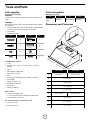
Parts supplied
Removing the packaging
CAUTION!
Remove carton carefully, wear gloves to protect against sharp
edges.
WARNING!
Remove the protective lm covering the product before putting
into operation.
• Hood assembly with blower and LED lamps already installed.
• 3
1
⁄4”x10” (82.5x254 mm) rectangular air transition
• Grease lters
• Hardware bag with:
Part Qty Part Qty
5x45 mm
6
10 x 60 mm wall
anchors
6
8x40 mm
6
5.4x75 mm screws
(for 10x60 mm wall
anchors)
6
4x8 mm
4
Ø 6.4x18 mm washers
2
4.5x13 mm
4
Torx 20 adapter
1
Tools/Materials required
• Level
• Drill with 1¼” (3.2 cm),
1
⁄8” (3.2 mm), and
1
⁄16” (4,8 mm)
drill bits
• Pencil
• Wire stripper or utility knife
• Tape measure or ruler
• Pliers
• Caulking gun and weatherproof caulking compound
• Vent clamps
• Jigsaw or keyhole saw
• Flat-blade screwdriver
• Metal snips
• Phillips screwdrive
r
Parts needed
• Home power supply cable
• ½” (12.7 mm) UL listed or CSA approved strain relief
• 3 UL listed wire connectors
For vented installations, you will also need:
• 1 wall or roof cap
• Metal vent system
Tools and Parts
Parts not supplied
Optional Accessories
Kit # Part Kit # Part
No Return
Valve
KIT02724 Recirculating KIT02770
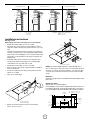
Dimensions and Clearances
I
A
B
C
D
E
F
G
H
ASG430SSA ASG436SSA
A 30” (76 cm) 36” (91.54 cm)
B 23” (58.5 cm)
C 10” (25.3 cm)
D 11
30
⁄32” (30 cm)
E 2
1
⁄8” (5.4 cm)
F 29
4
⁄32” (74 cm) 35
7
⁄32”(89.5 cm)
G 7
1
⁄2” (19 cm)
H 2
9
⁄16” (6.5 cm)
I
13
⁄32” (1 cm)

4
Electrical Requirements
IMPORTANT
Observe all governing codes and ordinances.
It is the customer’s responsibility:
To contact a qualied electrical installer.
To assure that the electrical installation is adequate and in
conformance with National Electrical Code, ANSI/NFPA 70
— latest edition*, or CSA Standards C22.1-94, Canadian
Electrical Code, Part 1 and C22.2 No.0-M91 - latest edition** and
all local codes and ordinances.
If codes permit and a separate ground wire is used, it is recom-
mended that a qualied electrician determine that the ground
path is adequate.
A copy of the above code standards can be obtained from:
National Fire Protection Association
1 Batterymarch Park
Quincy, MA 02169-7471
CSA International
8501 East Pleasant Valley Road
Cleveland, OH 44131-5575
• A 120 volt, 60 Hz., AC only, 15-amp, fused electrical circuit is
required.
• If the house has aluminum wiring, follow the procedure below:
1. Connect a section of solid copper wire to the pigtail leads.
2. Connect the aluminum wiring to the added section of
copper wire using special connectors and/or tools designed
and UL listed for joining copper to aluminum.
Follow the electrical connector manufacturer’s recommended
procedure. Aluminum/copper connection must conform with local
codes and industry accepted wiring practices.
• Wire sizes and connections must conform with the rating of
the appliance as specied on the model/serial rating plate.
The model/serial plate is located behind the lter on the rear
wall of the range hood.
• Wire sizes must conform to the requirements of the National
Electrical Code, ANSI/NFPA 70 (latest edition), or CSA
Standards C22. 1-94, Canadian Electrical Code, Part 1 and
C22.2 No. 0-M91 (latest edition and all local codes and
ordinances.
Venting Requirements
(ducted models only)
• Vent system must terminate to the outdoors, except for non
vented (recirculating) installations.
• Do not terminate the vent system in an attic or other enclosed
area.
• Do not use 4” (10.2 cm) laundry-type wall cap.
• Use metal vent only. Rigid metal vent is recommended.
Plastic or metal foil vent is not recommended.
• The length of vent system and number of elbows should
be kept to a minimum to provide efcient performance.
For the most efcient and quiet operation:
• Use no more than three 90° elbows.
• Make sure there is a minimum of 24” (61 cm) of straight vent
between the elbows if more than 1 elbow is used.
• Do not install 2 elbows together.
• Use clamps to seal all joints in the vent system.
• The vent system must have a damper. If the roof or wall cap has
a damper, do not use the damper supplied with the range hood.
• Use caulking to seal exterior wall or roof opening around the cap.
• The size of the vent should be uniform.
Cold weather installations
An additional back draft damper should be installed to minimize
backward cold air ow and a thermal break should be installed to
minimize conduction of outside temperatures as part of the vent
system. The damper should be on the cold air side of the thermal break.
The break should be as close as possible to where the vent
system enters the heated portion of the house.
Makeup air
Local building codes may require the use of makeup air systems
when using ventilation systems with greater than specied CFM
of air movement. The specied CFM varies from locale to locale.
Consult your HVAC professional for specic requirements in your area.
Preparation
Do not cut a joist or stud unless absolutely necessary. If a joist or
stud must be cut, then a supporting frame must be constructed.
Fittings material is provided to secure the hood to most types of
walls/ceilings.
However, a qualied technician must verify suitability of the mate-
rials in accordance with the type of wall/ceiling.
Before making cutouts, make sure there is proper clearance with-
in the ceiling or wall for exhaust vent.
Hood installation height above cooktop is the users preference.
The lower the hood is above the cooktop, the more efcient the
capturing of cooking odors, grease and smoke.
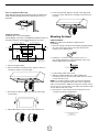
Venting Methods
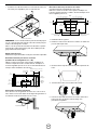
This hood is factory set for venting through the roof (vertical dis-
charge) or wall (horizontal discharge). A 3
1
⁄4” x 10” (82.5x254 mm)
rectangular duct system is needed for installation (not included).
The hood exhaust opening is 3
1
⁄4” x 10” (82.5x254 mm).
NOTE: Flexible vent is not recommended. Flexible vent creates
back pressure and air turbulence that greatly reduce perfor-
mance. Vent system can terminate either through the roof or wall.
To vent through a wall, a 90° elbow is needed.
For Non-Vented (recirculating) Installations
If it is not possible to vent cooking fumes and vapors to the
outside, the hood can be used in the non-vented (recirculating)
version, tting a pair of charcoal lters to the blower. Fumes and
vapors are recycled through the round grid. See optional acceso-
ries section.
CAUTION: Mount this hood so that the bottom edge is at 30”
(76.2 cm) minimum or 36” (91.4 cm) maximum above the cooking
surface. Household use, please, read installation manual for spe-
cic application. Check your ceiling height and the hood height
maximum before you select your hood.

5
A
A
A. Air exhaust transition
NOTE: The exhaust adaptor/damper can be installed up to 1
inch on either side of the hood center to accommodate offcenter
ductwork. In extreme offcenter installations, one end of the duct
connector may need to be trimmed to clear the electrical cable
clamp.
Mark holes
Select the vent option that your installation will require and proceed to
that section:
Outside top exhaust
(Vertical duct– 3
1
⁄4”x 10” Rectangular)
Use the diagram or the hood as a template and mark the locations on
the cabinet for ductwork, electrical wiring and keyhole screw slots. It
is recommended to make the marks before the cabinet’s installation.
13
⁄32” (1 cm) Wiring access knockout
(cabinet bottom side)
Mounting
screws (4)
Cabinet
front side
30” model: 6
11
⁄32” (16.1 cm)
36” model: 9
11
⁄32” (23.7 cm)
Vent
system hole
5
1
⁄2”
(14 cm)
5
1
⁄2”
(14 cm)
4
21
⁄64”
(11 cm)
7
7
⁄8”
(20 cm)
7
1
⁄2”
(19 cm)
2
9
⁄16”
(6.5 cm)
13
⁄32”
(1 cm)
Vent
shims
CENTER
LINE
Cabinet
bottom side
Venting through the roof Venting through the wall Non Vented (recirculating)
A
B
C
F
F
A
B
D
F
C
A
B
F
AC
E D
A. 3
1
⁄4” x 10” rectangular transition
B. 3
1
⁄4” x 10” duct
C. Cabinet
D. 90° elbow
E. Round recirculating grid
F. Installation height (above the cooking surface):
MIN: 30” (76.2 cm)
MAX: 36” (91 cm)
Installation instructions
Ducting version
After having chosen the vent option, proceed as follows:
• Prepare duct and conduit cut outs as needed.
• If possible, disconnect and move freestanding or slide-in
range from cabinet opening to provide easier access to rear
wall.
Otherwise put a thick, protective covering over countertop,
cooktop or range to protect from damage and debris. Select
a at surface for assembling the unit. Cover that surface with
a protective covering and place all canopy hood parts and
hardware in it.
• Determine and mark the centerline on the wall where the
canopy hood will be installed. Select a mounting height
comfortable for the user and mark on wall.
• Prepare duct and conduit cut outs as needed.
• Remove the duct knockouts using a at blade screwdriver
and a small hammer.
• Use the screwdriver by knocking out the pannel in similar
fashion to a scalpel.
• Take care of sharp edges.
B
A
A. Vertical discharge
B. Horizontal discharge
• Attach air exhaust transition over knockout opening
with 4 - 4x8 mm screws.

6
5. Insert the two blower springs to the top of the range hood
housing, secure it with the four mounting screws previously
released.
Mounting the Hood
Cabinet Installation
NOTE: Your cabinet must be able to support at least
88 lb (40 kg).
1. Drive a mounting screw (from the hardware package) partway
into each center of the narrow neck of the keyhole slots
marked on the cabinet bottom.
2. Install the 4 - 4 x 8 mm mounting screws. Leave a
1
⁄4”
(6.4 mm) gap between the wall and the back of the screw
head to slide range hood into place.
1
⁄4”
(6.4 mm)
3. Fix the wiring conduit of the hood.
4. Slide the hood back against the cabinet. Tighten the
mounting screws. Be sure the screw heads are in the narrow
neck of the keyhole slot.
NOTE: You should consider the wall’s construction material in
order to choose the right wall anchor and screw. For plywood
walls you should use the 10x60 mm wall anchors and the 5.4x75
mm screws. For concrete walls you should use the 8x40 mm wall
anchors and the 5x45 mm screws
5. Drive 2 pieces of the selected screws and washers in the
security holes (See the image below).
A
B
C
A. 4- 4x8 mm Mounting Screws
B. Washers
C. Security screws
For recessed bottom cabinet only
If the cabinets have front, side or back trim, make 2 wood shims the
width of the trim and attach them to the cabinet bottom recess on
both sides.
Wood shims
Outside rear exhaust
(Horizontal duct– 3
1
⁄4”x 10” Rectangular)
Use the diagram or the hood as a template and mark the locations on
the wall for ductwork, electrical wiring and keyhole screw slots.
CENTER LINE
Permanent
Mounting hole
2
1
⁄2”
(6.3 cm)
10
5
⁄8” (27 cm)
7” (17.7 cm)
30”: 13
13
⁄16” (35.15 cm)
36”: 16
13
⁄16” (42.77 cm)
30”: 13
13
⁄16” (35.15 cm)
36”: 16
13
⁄16” (42.77 cm)
7” (17.7 cm)
10
5
⁄8” (27 cm)
39
⁄64” (1.5 cm)
39
⁄64” (1.5 cm)
WALL
Permanent
Mounting hole
4
21
⁄64”
(11 cm)
1
3
⁄8” (3.5 cm)
5
1
⁄2”
(14 cm)
5
1
⁄2”
(14 cm)
1. Remove the grease lters.
2. Remove the blower mounting screws. Put the screws in a
safe place in order to use them again.
3. Set free the two blower springs from the top of the range
hood housing.
4. Flip the blower base to the rear face of the range hood.

7
Wall Installation
Install framing for hood support
1. Mark the screw hole locations indicated in the “Outside rear
exhaust” gure.
2. If drywall is present, cut away enough drywall to expose 2
vertical studs at the indicated holes location. Install two
horizontal supports between two wall studs at the bottom and
upper mounting holes installation location.
3. The horizontal support must be ush with the room side of the
studs. Use cleats behind both sides of the support to secure
wall studs.
4. Reinstall drywall and renish.
View from rear
Mounting
Support
Centerline of
Installation
Space
IMPORTANT: Framing must be capable of
supporting 100 lbs.
Cleats
5. Cut holes at marked locations for duct and electrical wiring.
Mounting the hood
1. Drive a mounting screw (from the hardware package) partway
into each center of the narrow neck of the keyhole slots
marked on the wall’s support frame.
NOTE: You should consider the wall’s construction material in
order to choose the right wall anchor and screw. For plywood
walls you should use the 10x60 mm wall anchors and the 5.4x75
mm screws. For concrete walls you should use the 8x40 mm wall
anchors and the 5x45 mm screws
2. Install the 2 pieces of the selected screws on the mountings
screws location (see the image). Leave a
1
⁄4” (6.4 mm) gap
between the wall and the back of the screw head to slide
range hood into place.
1
⁄4”
(6.4 mm)
3. Fix the wiring conduit of the hood.
4. Slide the hood back against the wall. Tighten the mounting
screws. Be sure the screw heads are in the narrow
neck of the keyhole slot.
A
B
C
D
B
A. Mounting Screws
B. Upper security screws (Wall Installation)
C. Lower security screws (Wall Installation)
D. Washers
5. Drive 2 pieces of the selected screws in the upper security
screws location (see the image above).
6. Drive 2 pieces of the selected screws and washers in the
lower security screws location (see the image above).
7. Connect Ductwork to hood.
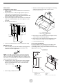
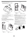
Recirculating Kit EXXRCK10
If it is not possible to vent cooking fumes and vapors to the
outside, the range hood can be used in the non-vented
(recirculating) version, using a charcoal lter and a recirculating
grid placed on the soft.
Recirculating through
the cabinet top wall
A
B
G
H
F
D
E
A. Ceiling
B. Recirculating grid
C. Soft
D. 6” round vent system
E. Range hood
F. Cabinet
G.Wall
H. 3
1
⁄4”x10” rect. to 6” round converter

8
Recirculating through
the soft
G
F
E
H
D
C
B
A
I
A. Ceiling
B. Recirculating grid
C. Soft
D. 6” round vent system
E. Range hood
F. Cabinet
G.Wall
H. 12” (30.5 cm) min. cabinet height
I. 3
1
⁄4”x10” rect. to 6” round converter
NOTE: 12” (30.5 cm) high cabinets without a soft may allow the
6” vent and vent cover to be seen.
8. Measure and mark the centerline of the cabinet top wall or
the soft above.
9. Measure from the bottom of the cabinet to the centerline of
the where the vent will come through the cabinet top wall or
the soft. Mark the location and use a saber saw or keyhole
saw to cut a 5¾” (14.6 cm) hole for the vent cover.
10. Cover the grill that protects the suction motor with the carbon
lter so that the slots on the lter correspond to the pins on
the sides of the motor protection grill.
11. Turn the carbon lter clockwise to block them (bayonet xing).
NOTE: The charcoal lters cannot be cleaned. It should be
replaced every 4-6 months (depending on hood usage).
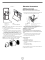
Electrical Connection
WARNING: Electrical Shock Hazard
Disconnect power before servicing.
Replace all parts and panels before operating.
Failure to do so can result in death or electrical shock.
1. Remove the knockout and the Junction box cover and install
the conduit connector (cULus listed) in junction box.
A
E
B
F
C
D
A. White wires
B. Black wires
C. UL listed wire connector
D. Green (or bare) and yellow-green ground wire
E. Home power supply cable
F. UL listed or CSA approved ½” strain relief
2. Run 3 wires; black, white and green, according to the National
Electrical Code and local codes and ordinances, in
1
⁄2”
conduit form service panel to junction box.
WARNING: Electrical Shock Hazard
Electrically ground blower.
Connect ground wire to green and yellow ground wire in
terminal box. Failure to do so can result in death or electrical
shock.
3. Connect black wire from service panel to black or red in
junction box, white to white and green to green-yellow.
4. Close and secure junction box cover.
Finall installation step
• Replace lters.
• Check operation of the hood.
If range hood does not operate:
• Check that the circuit breaker is not tripped or the house
fuse blown.
• Disconnect power supply.
• Check that wiring is correct.
Keep your Installation Instructions and Use and Care Guide close
to range hood for easy reference.

9
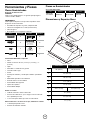
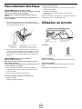
Hood Description
BA
C
D
E
A. Fan control switch
B. Light control switch
C. LED Lamps housings
D. Grease lter Handle
E. Grease lter
Description of control panel
Fan Low / OFF / Hi Ligth ON / OFF
LIGHT Control switch
Set light switch to ON or OFF.
FAN Control switch
Set fan switch to OFF, LOW or HI speed as needed.
Always use the high setting when grilling.
Range Hood Care
Cleaning
IMPORTANT: Clean the hood and grease lters frequently
according to the following instructions. Replace grease lters
before operating hood.
Exterior Surfaces:
To avoid damage to the exterior surface, do not use steel wool or
soap-lled scouring pads.
Always wipe dry to avoid water marks.
Cleaning Method:
• Liquid detergent soap and water, or all-purpose cleanser
• Wipe with damp soft cloth or nonabrasive sponge, then rinse
with clean water and wipe dry.
• Do not use cleaning agents containing bleach.
Aluminum Grease Filter:
1. Remove the lter by pulling the spring release handle and
then pulling down the lter.
A
A. Spring release handle
2. Wash aluminum grease lters as needed in dishwasher
or hot detergent solution.
3. Reinstall the lter by making sure the spring release handles
are toward the front. Insert aluminum lter into upper track.
4. Push in spring release handle.
5. Push up on aluminum lter and release handle to latch
into place.
Replacing a LED Lamp
The LED lights are replaceable by a service technician only. See
“Assistance and Service” section for service contact information.

Parts and Service Warranty:
For the period of one year from the date of the original purchase, we will provide free of charge, non consumable parts or components
that failed due to manufacturing defects. During this one year limited warranty, we will also provide, free of charge, all labor and in-
home service to replace the defective part.
What is Not Covered:
■ Damage to the product caused by oods, act of God, re and accidents.
■ Damage caused after delivery.
■ House fuses replacement or resetting of circuit breakers.
■ Service trips to your home to teach you how to use or install the product.
■ Light bulbs, metal, carbon lters and the other consumable parts.
■ The natural wear of nish, and wear due to improper maintenance, use of corrosive and abrasive cleaning
products, pads, and oven cleaner products.
This warranty will be voided when:
■ Product damaged due to improper installation and failure to follow installation instructions, delivery or maintenance.
■ Incidental or consequential damage caused by possible defects with this appliance.
■ Alteration or modication of the Product which may cause in damage to the Product, or failure to operate it
in accordance with specications.
■ Damage because of improper connection with equipment of other manufacturers.
■ Failure of the product if it is negligence, abused, misused, or used for other than the intended purpose or used commercially.
■ Improper repair, modication or servicing of the Product performed by third parties other than Authorized Agents.
Who is Covered:
This warranty is extended to the original purchaser for products purchased for ordinary home use in the 48 mainland states, Hawaii,
Washington D.C. Alaska, Guam, Puerto Rico and the Virgin Islands.
This warranty is non-transferable and applies only to the original purchaser and does not extend to subsequent
owners of this product. This warranty is made expressly in lieu of all other warranties, expressed or implied,
including, but not limited, any implied warranty of merchantability or tness for a particular purpose, and all other
obligations on the part of Elicamex, provided, however, that if the disclaimer of implied warranties is ineffective under applicable law,
the duration of any implied warranties arising by operation of law shall be limited to 1 (one) year from the date of original purchase at
retail or such longer period as may be required by applicable law.
This warranty does not cover any special, incidental and/or consequential damages, nor loss of prots, suffered by
the original purchaser, its customers and/or the users of the Product.
Have your product proof of purchase with date ready for warranty issues.
Or write to:
Who to contact
To obtain service under warranty or for any service related question, please visit the support section on the website below:
www.elica.com
Have your product proof of purchase with date ready for warranty issues.
TO OBTAIN SERVICE UNDER WARRANTY:
or any Service Related Questions, please call:
1-888-732-8018
Staple your receipt here.
Proof of the original purchase
date is needed to obtain service
under the warranty.
TO OBTAIN SERVICE UNDER WARRANTY: You must present proof of original purchase date.
Please keep a copy of your dated proof of purchase (sales slip) in order to obtain service under warranty.
WARRANTY

11
Tabla de contenidos
Instrucciones Importantes de Seguridad............................... 11
Herramientas y Piezas.......................................................... ... 12
Dimensiones y Espacios Libres............................................... 12
Requisitos Eléctricos................................................................ 13
Requisitos de Ventilación......................................................... 13
Métodos de Ventilación............................................................ 13
Instrucciones de Instalación.................................................... 14
Conexión Eléctrica.................................................................... 17
Descripción de la Campana..................................................... 18
Cuidado de la Campana........................................................... 18
Garantía.................................................................................. ... 19
APROBADO PARA APARATOS DE USO DOMÉSTICO
SÓLO PARA USO DOMÉSTICO
LEA Y GUARDE ESTAS INSTRUCCIONES
ANTES DE CONTINUAR, LEA LAS INSTRUCCIONES POR
COMPLETO.
LA INSTALACIÓN DEBE CUMPLIR CON TODA LA
NORMATIVA LOCAL.
IMPORTANTE: Guarde estas instrucciones para su uso por
parte del inspector de electricidad local.
INSTALADOR: Entregue al propietario estas instrucciones con
la unidad.
PROPIETARIO: Conserve estas instrucciones para futuras
consultas.
Advertencia de Seguridad: Antes de realizar el cableado de este
aparato, desactive el circuito de energía eléctrica en el panel de
servicio y desbloquee el panel.
Requisito: Circuito Auxiliar de R120 VAC, 60 Hz. 15 ó 20 A
INSTRUCCIONES IMPORTANTES DE SEGURIDAD
ADVERTENCIA: PARA REDUCIR EL RIESGO DE INCENDIOS,
CHOQUE ELÉCTRICO O LESIONES A PERSONAS, OBSERVE
LO SIGUIENTE:
■ Use esta unidad sólo de la manera para la que fue diseñada
por el fabricante. Si tiene preguntas, póngase en contacto
con el fabricante.
■ Antes de dar servicio o limpiar la unidad,apague el suministro
de energía en el panel de servicio y bloquee los medios
de desconexión del servicio para evitar que se encienda
accidentalmente el suministro de energía. Cuando el medio
de desconexión del servicio no se pueda bloquear, sujete de
manera segura un dispositivo de advertencia prominente,
como podría ser una etiqueta, al panel de servicio.
■ La instalación y el cableado se debe llevar a cabo por una
persona(s) calicada(s), de acuerdo con los códigos y
estándares aplicables, incluida la construcción ignífuga.
■ Es necesaria una ventilación suciente para la correcta
combustión y expulsión de gases por la salida de humos
(chimenea) del equipo de combustión de carburante para
evitar el contratiro. Siga las directrices de fabricantes de
equipos de calefacción y los estándares de seguridad como
los publicados por la National Fire Protection Association
(NFPA), American Society for Heating, Refrigeration and Air
Conditioning Engineers (ASHRAE) y las normativas locales.
■ Al efectuar oricios en una pared o techo, no dañe el
ecableado eléctrico y otras instalaciones ocultas.
■ Los conductos deben tener ventilación con salida al exterior.
CUIDADO: Para usarse sólo en ventilación común. No lo use
para ventilar materiales y vapores peligrosos o explosivos.
CUIDADO: Para reducir el riesgo de incendio y para ventilar el
aire adecuadamente, asegúrese de dirigir el conducto de
ventilación hacia el exterior - no ventile el aire de salida a
espacios dentro de paredes o techos, áticos, espacios
angostos o garajes.
ADVERTENCIA: PARA REDUCIR EL RIESGO DE INCENDIO,
SÓLO USE CONDUCTOS METÁLICOS.
ADVERTENCIA: PARA REDUCIR EL RIESGO DE INCENDIO
PROVOCADO POR GRASA EN LA SUPERFICIE DE LA ESTUFA:
■ Nunca deje las unidades de supercie sin vigilancia cuando
estén en ajustes altos. La cocción puede causar humo o
reboses de grasa que pueden prender fuego. Caliente el
aceite a fuego lento o medio.
■ Siempre ENCIENDA la campana cuando cocine con calor
alto o cuando amee alimentos (por ejemplo, crepes Suzette,
cerezas Jubileo y ameado de carne de res con pimienta).
■ Limpie los ventiladores con frecuencia. No permita que la
grasa se acumule en el ventilador o en el ltro.
■ Use un tamaño de sartén adecuado. Siempre use utensilios de
cocción que sean los adecuados para el tamaño del elemento
de la supercie.
ADVERTENCIA: PARA REDUCIR EL RIESGO DE LESIONES A
PERSONAS SI SE PRENDE FUEGO EN LA SUPERFICIE DE LA
ESTUFA OCASIONADO POR GRASA, OBSERVE LO SIGUIENTE:
a
■ EXTINGA LAS LLAMAS con una tapa que encaje bien, una
bandeja para galletas o una bandeja metálica y luego apague
el quemador. TENGA CUIDADO PARA EVITAR QUEMADURAS.
Si las llamas no se extinguen de inmediato, EVACUE Y
LLAME AL DEPARTMENTO DE BOMBEROS.
■ NUNCA TOME UNA CACEROLA QUE ESTÉ ARDIENDO -
podría quemarse.
■ NO UTILICE AGUA, incluyendo paños para vajilla o toallas
mojadas - podría ocurrir una explosión de vapor violenta.
■ SÓLO use un extinguidor si:
-Sabe a ciencia cierta que tiene un extinguidor de clase
ABC y ya sabe cómo utilizarlo.
– El incendio es pequeño y se encuentra contenido en el
lugar en donde se inició.
– Ha llamado al departamento de bomberos.
– Puede apagar el fuego con su espalda mirando hacia una
una salida.
a
Basado en “Consejos de seguridad para fuegos se cocina”
publicado por NFPA.
ADVERTENCIA: A n de reducir el riesgo de incendio
o de choque eléctrico, no use este ventilador con ningún
dispositivo semiconductor para el control de la velocidad.
LEA Y GUARDE ESTAS INSTRUCCIONES

12
Herramientas y Piezas
Piezas Suministradas
Remoción de la Confección
CUIDADO
Quite la caja cuidadosamente, use guantes para protegerse
contra los bordes alados.
ADVERTENCIA
Quite la película de protección que cubre el producto antes
de ponerlo en funcionamiento.
• Ensamble de campana con motor y lámparas LED
• Transición rectangular de 3
1
⁄4”x10” (82.5x254 mm).
• Filtros de grasa
• Bolsa plástica con el siguiente contenido:
Pieza Cantidad Pieza Cantidad
5x45 mm
6
Taquetes 10 x 60 mm
6
8x40 mm
6
Tornillos de 5.4x75 mm
(para taquetes
de 10 x 60 mm)
6
4x8 mm
4
Rondanas de
Ø 6.4x18 mm
2
4.5x13 mm
4
Adaptador Torx 20
1
Herramientas/Materiales requeridos
• Nivel
• Taladro con brocas de 1¼” (3.2 cm),
1
⁄8” (3.2 mm), y
1
⁄16”
(4,8 mm)
• Lápiz
• Pelacables o cuchillo de uso general
• Cinta de medir o regla
• Pinzas
• Pistola para calafateo y masilla para calafateo a prueba de
agua
• Abrazaderas para ducto de ventilación
• Sierra de vaivén o sierra caladora
• Destornillador de hoja plana
• Tiijeras de hojalatero
• Destornillador Phillips
Piezas necesarias
• Cable de suministro eléctrico doméstico
• Protector de cables de ½” (12.7 mm) que esté en la lista de
UL o aprobado por CSA
• 3 conectores para cables que estén en la lista de UL
Para instalaciones con ducto de escape, también necesitará:
• 1 cubierta para pared o techo
• Sistema de ventilación metálico
Piezas no Suministradas
Accesorios Opcionales
Kit # Pieza Kit # Pieza
Válvula de
no retorno
KIT02724 Recirculante KIT02770
Dimensiones y Espacios libres
I
A
B
C
D
E
F
G
H
ASG430SSA ASG436SSA
A 30” (76 cm) 36” (91.54 cm)
B 23” (58.5 cm)
C 10” (25.3 cm)
D 11
30
⁄32” (30 cm)
E 2
1
⁄8” (5.4 cm)
F 29
4
⁄32” (74 cm) 35
7
⁄32”(89.5 cm)
G 7
1
⁄2” (19 cm)
H 2
9
⁄16” (6.5 cm)
I
13
⁄32” (1 cm)

13
Requisitos Eléctricos
IMPORTANTE
Observe todos los códigos y reglamentos aplicables.
Es la responsabilidad del propietario:
Contactar un instalador eléctrico calicado.
Asegurarse de que la instalación eléctrica es adecuada y en
conformidad con National Electrical Code, ANSI/NFPA 70
— última edición* o CSA Standards C22.1-94, Canadian
Electrical Code, Parte 1 y C22.2 No.0-M91 — última edición**
y toda la normativa y las ordenanzas locales.
Si la normativa lo permite y se utiliza un cable de toma a tierra
independiente, se recomienda que un electricista calicado de-
termine si la difracción de onda de tierra es laadecuada.
Una copia de las normas que se mencionaron anteriormente, se
pueden obtener de:
National Fire Protection Association
1 Batterymarch Park
Quincy, MA 02169-7471
CSA International
8501 East Pleasant Valley Road
Cleveland, OH 44131-5575
• Se necesita un circuito eléctrico de 120 voltios, 60 hertzios,
CA solamente, de 15 amperios y protegido con fusibles.
• Si la casa tiene cableado de aluminio, siga el procedimiento a
continuación:
1. Conecte una sección de alambre de cobre sólido a los
conductores exibles.
2. Conecte el cableado de aluminio a la sección añadida de
alambre de cobre usando conectores especiales y/o
herramientas diseñadas y de la lista de UL para unir el cobre
al aluminio.
Siga el procedimiento recomendado por el fabricante del
conector eléctrico. La conexión de cobre/aluminio deberá
hacerse en conformidad con los códigos locales y las prácticas
de cableado aceptadas por la industria.
• Los tamaños de los cables y las conexiones deben cumplir
de acuerdo con la clasicación del electrodoméstico, como
se especica en la placa de clasicación del modelo/de la
serie. La placa del modelo/de la serie está ubicada detrás del
ltro, en la pared posterior de la campana para cocina.
• El tamaño de los cables debe cumplir con los requisitos del
National Electrical Code (Código Nacional Eléctrico), ANSI/
NFPA 70 (última edición) o las normas de CSA C22. 1-94
Canadian Electrical Code (Código Canadiense de
Electricidad), Parte 1 y C22.2 N° 0-M91 (última edición),
y todos los códigos y ordenanzas locales.
Requisitos de Ventilación
(Modelos con ducto de escape solamente)
• El sistema de ventilación debe terminar en el exterior, excepto
para las instalaciones sin ducto de escape (con recirculación).
• No dirija la salida del sistema de ventilación hacia el desván u otra
área cerrada.
• No utilice una cubierta de pared de tipo para lavandería de
4” (10,2 cm).
• Utilice ducto de escape de metal únicamente. Se recomienda
un ducto de escape de metal rígido. No se recomienda ducto
de escape de plástico u hoja metálica.
• El largo del sistema de ventilación y el número de codos
se deben mantener al mínimo para proveer un funcionamiento
ecaz.
Para obtener el funcionamiento más ecaz y silencioso:
• No use más de 3 codos de 90°.
• Asegúrese de que haya un mínimo de 24” (61 cm) de ducto
de escape recto entre los codos, si se utiliza más de 1 codo.
• No instale 2 codos lado a lado.
• Use abrazaderas para sellar todas las juntas en el sistema de
ventilación.
• El sistema de ventilación debe tener una compuerta. Si la
cubierta del techo o la pared tiene una compuerta, no use la
compuerta provista con la campana de cocina.
• Utilice masilla de calafateo para sellar la abertura exterior de la
pared o el techo alrededor de la cubierta.
• El tamaño del ducto de escape debe ser uniforme.
Instalaciones en climas fríos
Una válvula de no retorno adicional debe ser instalada para
reducir el ujo de aire frío como parte del sistema de ventilación.
Un break térmico debe ser instalado para reducir la conducción
de las temperaturas exteriores al interior del sistema de
ventilación.
La válvula deberá estar en el lado del aire frío del break térmico.
Reguladores de aire
Los códigos de construcción local sugieren el uso de sistemas
reguladores de aire cuando se usen sistemas de ventilación
mayores a la CFM especicada o al movimiento del aire. El CFM
especicado varía dependiendo del área. Consulte a un técnico
en ventilación para conocer los requerimientos de su área.
Preparación
No corte vigas si no es absolutamente necesario. Si alguna viga
debe ser cortada, una estructura de soporte debe ser construida.
Los materiales de instalación son provistos tratando de asegurar
el montaje correcto en la mayoría de los soportes.
En cualquier caso, un técnico calicado debe vericar que los
materiales sean correctos dependiendo del tipo de soporte.
Antes de realizar cualquier corte, asegúrese de que existan las
dimensiones adecuadas para el ducto de ventilación.
Métodos de Ventilación
Esta campana se ha ajustado de fábrica para tener una venti-
lación a través del techo o de la pared.
Se requiere un sistema de ventilación rectangular de 3
1
⁄4” x 10”
(82.5x254 mm) para la instalación (no incluido). La abertura de
ventilación de la campana es de 3
1
⁄4” x 10” (82.5x254 mm).
NOTA: No se recomienda el uso de ductos de escape exibles.
Los ductos de escape exibles crean contrapresión y turbulencia
de aire, lo cual reduce el desempeño en gran medida. El sistema
de ventilación debe terminar a través del techo o la pared. Para
colocar el ducto a través de la pared, se necesita un codo de 90°.

14
Para instalaciones recirculantes
Si no es posible expulsar los humos y vapores al exterior, la
campana puede ser congurada a su versión recirculante, insta-
lando un par de ltros de carbón al motor. Los humos y vapores
recircularán a través de una rejilla redonda. Vea la sección de
Accesorios opcionales.
Instrucciones de Instalación
Versión con tubos
Después de haber escogido la opción de descarga, proceder
como sigue:
• Prepare el ducto y cortes necesarios
• Si es posible, desconecte y mueva individualmente o deslice
la estufa desde la apertura del gabinete para permitir un
acceso fácil al muro posterior. De lo contrario, coloque una
cubierta protectora gruesa sobre la encimera o la cocina para
protegerla de daños o suciedad.
Seleccione una supercie plana para montar la unidad.
Coloque una cubierta protectora sobre la supercie y ponga
sobre ella todas las piezas de la carcasa de la campana,
tornillos y elementos metálicos.
• Determine y marque la línea central en el muro donde se
instalará la carcasa de la campana.
• Seleccione una altura de montaje confortable para el usuario
y realice una marca en el muro situado detrás de la estafa.
• Preparar los cortes de los conductos y de los tubos, así como
es requerido.
• Quitar los precortes del conducto usando un destornillador
plano y un martillo pequeño. Dé unos pequeños golpes para
remover la cubierta, utilizando el martillo y destornillador de
forma similar a la que se hace con un cincel.
• Ponga atención a los los cortantes.
A
B
A. Descarga vertical
B. Descarga horizontal
• Fijar la transición rectangular sobre la apertura del precorte
con 4 tornillos de 4x8 mm.
A
A
A. Transición para salida de aire
NOTA: La transición se puede colocar hasta 1” del centro de
la campana para acomodarse a instalaciones descentradas.
En instalaciones extremadamente descentradas, un lado de la
transición deberá ser recortada para evitar interferencias con la
abrazadera del cable.
Marcar los oricios
Seleccionar la opción de descarga que requiere su instalación y pro-
ceder a esa sección:
PRECAUCIÓN: Monte esta campana de modo que el borde
inferior esté al menos a 30” (76.2 cm) ó máximo a 36” (91.4
cm) sobre la supercie de cocinado. Lea el manual para casos
especícos. Verique la altura de su techo antes de seleccionar
su campana.
Ventilación a través del techo Ventilación a través de la pared Sin ductos (recirculante)
A
B
C
F
F
A
B
D
F
C
A
B
F
AC
E D
A. Transición rectangular de 3
1
⁄4” x 10”
B. Ducto de 3
1
⁄4” x 10”
C. Gabinete
D. Codo de 90°
E. Rejilla recirculante
F. Altura de instalación (Por encima de la supercie de cocinado):
MIN: 30” (76.2 cm)
MAX: 36” (91 cm)

15
Extracción superior al exterior
(Conducto vertical - 3
1
⁄4”x 10” Rectangular)
Usar el diagrama o la campana como plantilla y marque en el
gabinete la ubicación del ducto, cableado eléctrico y puntos de
sujeción. Es recomendable realizar los cortes al gabinete antes
de instalarlo.
13
⁄32” (1 cm) Precorte para cableado
(Cara inferior del gabinete)
Tornillos de
instalación (4)
Parte frontal
del gabinete
Modelo 30”: 6
11
⁄32” (16.1 cm)
Modelo 36”: 9
11
⁄32” (23.7 cm)
Apertura del ducto
de ventilación
5
1
⁄2”
(14 cm)
5
1
⁄2”
(14 cm)
4
21
⁄64”
(11 cm)
7
7
⁄8”
(20 cm)
7
1
⁄2”
(19 cm)
2
9
⁄16”
(6.5 cm)
13
⁄32”
(1 cm)
Tiras de
soporte
LÍNEA DE
CENTRO
Cara inferior
del gabinete
Sólo para gabinetes huecos:
Si los gabinetes tienen perles frontales, laterales o posteriores,
hacer 2 soportes de madera con el ancho del perl y ensámble-
los a ambos lados de la parte inferior del gabinete.
Tiras de madera
Extracción posterior al exterior
(Conducto Horizontal 3
1
⁄4”x 10” Rectangular)
Usar el diagrama o la campana como plantilla y marque en el
gabinete la ubicación del ducto, cableado eléctrico y puntos de
sujeción.
LÍNEA DE CENTRO
Oricio de montaje
de seguridad
2
1
⁄2”
(6.3 cm)
10
5
⁄8” (27 cm)
7” (17.7 cm)
30”: 13
13
⁄16” (35.15 cm)
36”: 16
13
⁄16” (42.77 cm)
30”: 13
13
⁄16” (35.15 cm)
36”: 16
13
⁄16” (42.77 cm)
7” (17.7 cm)
10
5
⁄8” (27 cm)
39
⁄64” (1.5 cm)
39
⁄64” (1.5 cm)
PARED
Oricio de montaje
de seguridad
4
21
⁄64”
(11 cm)
1
3
⁄8” (3.5 cm)
5
1
⁄2”
(14 cm)
5
1
⁄2”
(14 cm)
1. Retire los ltros de grasa
2. Retire los tornillos de instalación del motor. Colóquelos en un
lugar seguro para volver a utilizarlos.
3. Libere los dos clips de sujeción del motor de la parte superior
de la campana
4. Voltee la base del motor a la cara posterior de la campana
5. Inserte los dos clips de sujeción del motor a la parte posterior
de la campana. Asegure el motor con los 4 tornillos
previamente retirados.
Montaje de la campana
Installación al gabinete
NOTA: Su gabinete debe ser capas de soportar al menos 88 lb
(40 kg).
1. Inserte un tornillo de instalación al centro de la parte
angosta de los oricios de instalación marcados en la parte
baja del gabinete.
2. Instale 4 tornillos de 4 x 8 mm. Deje la cabeza del tornillo
despegada aprox.
1
⁄4” (6.4 mm) de la base para deslizar la
campana en su lugar.
1
⁄4”
(6.4 mm)
3. Fije el conducto de los cables a la campana.
4. Deslice la parte superior de la campana al gabinete
Ajuste los tornillos de montaje. Asegúrese de que la cabeza
de los tornillos estén en la parte angosta de los oricios de
instalación.
NOTA: Debe considerar los materiales de construcción de
la pared para escoger los tornillos y taquetes de instalación
correctos. Para paredes de tablaroca debe utilizar los taquetes
de 10x60 mm y los tornillos de 5.4x75 mm. Para paredes de
concreto debe usar los taquetes de 8x40 mm y los tornillos de
5x45 mm.

16
5. Coloque 2 de los tornillos seleccionados y 2 rondanas en los
oricios de seguridad (Vea la imagen).
A
B
C
A. 4 tornillos de instalación de 4 x 8 mm
B. Rondanas
C. Tornillos de seguridad
Instalación a la pared
Instalación del marco de soporte para la campana
1. Marque la ubicación de los barrenos indicados en la gura de
la sección “Extracción posterior al exterior”.
2. Si la pared en cuestión es de tablaroca, corte y quite un área
suciente para exponer al menos 2 vigas verticales cerca de
las marcas de los oricios. Instale dos soportes horizontales
entre las dos vigas de la pared en la ubicación de los
barrenos superiores e inferiores de instalación.
3. Los soportes horizontales deben estar alineados con la vigas
internas de la pared. Utilice abrazaderas detrás de ambos
lados de los soprtes para asegurar a las vigas.
4. Reinstale la pared de yeso y dé los acabados.
Vista trasera
Soporte de
montaje
Línea de
centro del
área de
instalación
IMPORTANTE: La estructura debe
soportar 100 lbs.
NOTA: Debe considerar los materiales de construcción de
la pared para escoger los tornillos y taquetes de instalación
correctos. Para paredes de tablaroca debe utilizar los taquetes
de 10x60 mm y los tornillos de 5.4x75 mm. Para paredes de
concreto debe usar los taquetes de 8x40 mm y los tornillos de
5x45 mm.
5. Instale 2 piezas de los tornillos seleccionados en la ubicación
de los tornillos de instalación (ver la imagen). Deje la cabeza
del tornillo despegada aprox.
1
⁄4” (6.4 mm) de la base para
deslizar la campana en su lugar.
1
⁄4”
(6.4 mm)
6. Fije el conducto de los cables a la campana.
7. Deslice la parte trasera de la campana contra la pared.
Apriete los tornillos. Asegúrese de que la cabeza de los
tornillos quede en la parte angosta de las llaves.
A
B
C
D
B
A. Tornillos de instalación
B. Tornillos de seguridad superiores (Instalación a pared)
C. Tornillos de seguridad inferiores (Instalación a pared)
D. Rondanas
8. Coloque 2 de los tornillos seleccionados en la ubicación de
los tornillos de seguridad superiores (vea la imagen).
9. Coloque 2 de los tornillos seleccionados y 2 rondanas en la
ubicación de los tornillos de seguridad inferiores (vea la imagen).
10. Conecte los ductos a la campana.
Kit Recirculante EXXRCK10 (no incluido)
Si no es posible enviar al exterior los humos y vapores de cocina,
la campana puede ser utilizada en su versión recirculante, utili-
zando 2 ltros de carbón y una rejilla recirculante colocada en el
soto o en la pared superior del gabinete.
Versión recirculante a través
de la pared superior del gabinete
A
B
G
H
F
D
E
A. Techo
B. Rejilla recirculante
C. Soto
D. Ducto de Ø 6”
E. Campana
F. Gabinete
G.Pared
H. Convertidor de 3
1
⁄4”x10” rect. a Ø 6”

17
Versión recirculante
a través del soto
G
F
E
H
D
C
B
A
I
A. Techo
B. Rejilla recirculante
C. Soto
D. Ducto de Ø 6”
E. Campana
F. Gabinete
G. Pared
H. Gabinete de 12” (30.5 cm) de altura
I. Convertidor de 3
1
⁄4”x10” rect. a Ø 6”
NOTA: Los gabinetes de 12” (30.5 cm) de altura sin soto, per-
miten ver el ducto de salida del aire.
1. Mida y marque la línea de centro de la pared superior del
gabinete o del soto.
2. Mida desde la parte baja del gabinete hasta el centro de la
ubicación seleccionada para la rejilla (pared superior del
gabinete o soto). Marque la ubicación y urilice una sierra
caladora o serrucho para cortar una circunferencia de 5¾”
(14.6 cm) para la rejilla recirculante.
3. Cubra la rejilla que protege el motor del soplador con el ltro
de carbón, de manera que las ranuras del ltro coincidan con
las espigas en los lados de la rejilla del motor.
4. Gire el ltro de carbón hacia la derecha para asegurarlo.
NOTA: El ltro de carbón no se puede lavar. Deberá durar hasta 6
meses con el uso normal.
Conexión eléctrica
ADVERTENCIA: Peligro de descarga eléctrica
Antes de realizar el cableado de este aparato, desactive el cir-
cuito de energía eléctrica en el panel de servicio.
Vuelva a colocar las partes antes de poner en funcionamiento.
1. Retire el pestillo extraíble y la tapa de la caja de conexiones e
instale el conductor de cables (Listado en cULus) a la caja de
conexiones.
A
E
B
F
C
D
A. Cables blancos
B. Cables negros
C. Conector de cables UL
D. Cable de tierra verde (o desnudo) o verde / amarillo
E. Cable de alimentación
F. Pasa cables de ½” aprobado por UL o CSA
2. Coloque 3 cables (Negro, blanco y verde) de acuerdo con
el National Electrical Code y la normativa y las ordenanzas
locales en el canal de cables de
1
⁄2” del panel del servicio a la
caja de conexiones.
ADVERTENCIA: Peligro de descarga eléctrica
Aterrizar el motor a tierra.
Conecte el cable de tierra verde o amarillo en la caja eléctrica.
3. Conecte el cable negro del panel de servicio al cable negro
o rojo de la caja de conexiones, el blanco al blanco y el verde al
verde-amarillo.
4. Cierre la tapa de la caja de conexiones.
Últimos pasos de la instalación
• Vuelva a colocar los ltros de grasa.
• Verique el funcionamiento de la campana.
Si la campana no enciende:
• Desconecte el suministro de energía.
• Verique que los cables estén bien conectados o no esté
fundido algún fusible en casa.
• Verique que el cableado sea correcto.

18
Descripción de la campana
BA
C
D
E
A. Switch del motor
B. Switch de las lámparas
C. Lámparas LED
D. Seguro del ltro de grasa
E. Filtro de grasa
Descripción de los controles
Velocidad del Motor Low / OFF / Hi Lámparas ON / OFF
Switch de Lámparas
Presione la posición ON del switch para encender las lámparas y
OFF para apagarlas.
Switch de Motor
Presione el switch en la velocidad deseada: OFF (apagado), LOW
(baja) o HI (alta).
Utilice siempre la velocidad alta cuando esté cocinando.
Cuidado de la campana
Limpieza
IMPORTANTE: Limpie con frecuencia la campana y los ltros
para grasa de acuerdo a las instrucciones a continuación. Vuelva
a colocar los ltros para grasa antes de poner a funcionar la
campana.
Supercies Externas:
Para evitar daños a la supercie exterior, no use estropajos de
acero ni jabonosos.
Siempre séquela con un paño para evitar manchas de agua.
Método de limpieza:
• Detergente líquido y agua o producto de limpieza general.
• Límpiela con un paño suave húmedo o una esponja no
abrasiva, enjuáguela con agua limpia y séquela con un paño.
• No utilice agentes de limpieza que contengan cloro.
Filtros de grasa de aluminio:
1. Para quitar el ltro, jale la manija de liberación con resorte
y jale el ltro hacia abajo.
A
A. Seguro de liberación del ltro
2. Lave los ltros de metal cuando sea necesario en la
lavavajillas o con una solución caliente de detergente.
3. Vuelva a instalar el ltro asegurándose de que las manijas de
liberación con resorte estén mirando hacia el frente.
4. Empuje hacia dentro la manija de liberación con resorte.
5. Empuje el ltro de metal hacia arriba y suelte la manija para
que se trabe en su lugar.
Reemplazar las Lámparas LED
Los luces LED son reemplazables sólo por un técnico de servicio.
Para obtener información de contacto del servicio, lea la infor-
mación al calce.
IMPORTANTE: Guarde el empaque original en caso de que sea necesario el retorno del producto.
¿Tiene problemas con el montaje de
su producto?¿Faltan piezas?
entre las 7 a.m. y las 4 p.m. (Horario del Pacífico), Lunes - Viernes
o escriba a:
elica@servicepower.com
(incluya un nombre de contacto, modelo, número serial, ticket de compra y la hora en la que preferiría que se le contacte)
¡NO LO REGRESE A LA TIENDA!
¡para todas las piezas de reemplazo y cualquier
duda que tenga acerca de este producto!

Garantía de componentes y servicio:
Por un periodo de un año desde la fecha original de compra, ofreceremos sin costo alguno, el reemplazo de piezas no
consumibles o componentes que han fallado debido a defectos de fabricación.
Durante este año de garantía limitada, también ofreceremos sin costo alguno, la mano de obra y el servicio en su domicilio
para reemplazar la parte defectuosa.
Lo que no cubre:
■ Daños a la campana ocasionados por inundaciones, actos de Dios, fuego y accidentes.
■ Daños causados después de la entrega.
■ Reemplazo de fusibles o el reajuste de la caja de contactos del circuito eléctrico.
■ Viajes de servicio a su domicilio para enseñarle a usar o instalar el producto.
■ Lámparas, ltros de grasa, ltros de carbón y otras partes consumibles.
■ El desgaste natural del acabado, así como el desgaste ocasionado por el mantenimiento inadecuado, el uso de productos para
limpieza corrosivos y abrasivos, y otros limpiadores para hornos.
Esta Garantía será anulada cuando:
■ El producto ha sido dañado debido a una instalación inadecuada y no haber seguido las instrucciones para su instalación,
traslado o mantenimiento.
■ Daños Incidentales o de consecuencia causados por posibles defectos de este electrodoméstico.
■ Daños por alteración o modicación, al producto que puedan causar fallas en la operación de acuerdo con las especicaciones
funcionales.
■ Daños debidos a conexiones inapropiadas con equipos de otros fabricantes.
■ Daños al producto por ser usado con negligencia, abuso, uso indebido o utilizado para otros propósitos al cual fue fabricado, o
bien uso comercial.
■ Reparaciones, modicaciones o servicios inadecuados realizados al producto por agentes no autorizado
Quién está cubierto:
Esta garantía se extiende al comprador original para productos comprados para uso doméstico en los 48 estados principales
de los Estados Unidos de América, Hawaii, Washington D.C., Alaska, Guam, Puerto Rico y las Islas Vírgenes.
Esta garantía es intransferible y aplica solamente para el comprador original y no se extiende a los propietarios subsecuentes
de este producto. La presente garantía sustituye expresamente cualquier otra garantía, ya sea expresa o implícita, incluyendo,
sin limitar, todas las garantías implícitas de comerciabilidad o idoneidad para un n concreto, así como todas las demás
obligaciones a cargo de Elicamex. Sin embargo, en caso de que la renuncia a las garantías implícitas resultara inaplicable
de acuerdo a la ley vigente, la vigencia de cualquier garantía implícita derivada de la aplicación de la ley será limitada a un
periodo de 1 (un) año, contado a partir de la fecha de compraventa originaria al menudeo, o por un periodo mas amplio en
caso de que éste último sea previsto por la ley aplicable.
Esta garantía no cubre ningun daño especial, fortuito y/o consecuente, ni la pérdida de benecios, sufridos por el comprador
original, de sus clientes y/o de los usuarios del producto.
A quién contactar:
Para obtener servicio bajo la garantía o por cualquier servicio relacionado a dudas o preguntas, por favor visite la sección de soporte
en la página web que se muestra a continuación:
www.elica.com
Tenga su comprobante de compra con la fecha, lista para cuestiones de garantía.
OBTENER SERVICIOS BAJO GARANTÍA:
O cualquier Pregunta Relacionada con los
Servicios, por favor, llame: 1-888-732-8018
Engrape su recibo aquí.
Como demostración de la adquisición,es
necesaria la fecha, para cualquier servicio
bajo garantía.
OBTENER SERVICIOS BAJO GARANTÍA: Usted debe presentar una prueba de la fecha original de
adquisición. Conserve una copia de su nota de compras con fecha, para obtener servicios bajo garantía.
GARANTÍA

20
Sommaire
Importantes Instructions de Sécurité..................................... 21
Outils et Pièces......................................................................... 22
Dimensions et Dégagement................................................... . 22
Spécications Électriques....................................................... 23
Exigences Concernant l’évacuation........................................ 23
Possibilité d’évacuation............................................................24
Instructions d’installation......................................................... 24
Raccordement Électrique........................................................ 28
Utilisation de la Hotte............................................................... 28
Entretien de la Hotte................................................................. 29
Garantie.................................................................................... ..30
APPROUVÉ COMME APPAREIL DOMESTIQUE
POUR UNE UTILISATION RÉSIDENTIELLE SEULEMENT
LISEZ CES INSTRUCTIONS ET CONSERVEZ-LES
VEUILLEZ LIRE CES INSTRUCTIONS AU COMPLET AVANT
DE COMMENCER.
L’INSTALLATION DE L’APPAREIL DOIT RESPECTER TOUS
LES CODES EN VIGUEUR.
IMPORTANT: Conservez ces instructions an de pouvoir les
remettre à l’inspecteur-électricien de votre région.
INSTALLATEUR: Veuillez laisser ces instructions avec l’appareil
pour le propriétaire.
PROPRIÉTAIRE:Veuillez conserver ces instructions pour
pouvoir vous y référer plus tard.
Avertissement de sécurité: Coupez l’alimentation du circuit
dans le panneau électrique et verrouillez le panneau avant de
raccorder les ls de cet appareil
Requirement 120 VAC, 60 Hz. 15 or 20 A Branch Circuit
La page est en cours de chargement...
La page est en cours de chargement...
La page est en cours de chargement...
La page est en cours de chargement...
La page est en cours de chargement...
La page est en cours de chargement...
La page est en cours de chargement...
La page est en cours de chargement...
La page est en cours de chargement...
La page est en cours de chargement...
La page est en cours de chargement...
La page est en cours de chargement...
-
 1
1
-
 2
2
-
 3
3
-
 4
4
-
 5
5
-
 6
6
-
 7
7
-
 8
8
-
 9
9
-
 10
10
-
 11
11
-
 12
12
-
 13
13
-
 14
14
-
 15
15
-
 16
16
-
 17
17
-
 18
18
-
 19
19
-
 20
20
-
 21
21
-
 22
22
-
 23
23
-
 24
24
-
 25
25
-
 26
26
-
 27
27
-
 28
28
-
 29
29
-
 30
30
-
 31
31
-
 32
32


dans d''autres langues
Documents connexes

Autres documents
-
ELICA ESR436SS Guide d'installation
-
-
-
Electrolux Icon E36WV60PPS Le manuel du propriétaire
-
Samsung NK30N7000UG/AA Manuel utilisateur
-
ELICA EAL336S1 Le manuel du propriétaire
-
-
GE PVWC930 Owner's Manual and Installation Instructions
-
-