Comfort Glow DVN11/DVP11/DVN17/DVP17/DVN25/DVP25 Le manuel du propriétaire
- Taper
- Le manuel du propriétaire

* All Pictures In This Manual Are For Illustrative Purposes Only. Actual Product May Vary.
© 2023 World Marketing of America, Inc, 12256 William Penn Hwy, Mill Creek, PA 17060
PH: 1-800-776-9425
Email: info@worldmkting.com
THIS MANUAL IS SUBJECT TO CHANGE WITHOUT NOTICE.
Owner’s Instruction and Operation Manual
Save These Instructions In A Safe Place For Future Reference.
CALIFORNIA PROPOSITION 65 WARNING:
This product can expose you to chemicals including carbon
monoxide, which is known to the State of California to cause
cancer, birth defects, and/or other reproductive harm. For
more information, go to www.P65warnings.ca.gov
INSTALLER: Leave this manual with the appliance.
CONSUMER: Retain this manual for future reference.
Please read this manual BEFORE
installing and operating this unit.
Do not store or use gasoline or other ammable vapors and liquids in the vicinity of this or any other appliance.
WHAT TO DO IF YOU SMELL GAS:
•Do not try to light any appliance.
•Do not touch any electrical switch; do not use any phone in your building.
•Leave the building immediately.
•Immediately call your gas supplier from a neighbor’s phone. Follow the gas supplier’s instructions.
•If you cannot reach your gas supplier, call the re department.
Installation and service must be performed by a qualied installer, service agency or the gas supplier.
WARNING:
FIRE OR EXPLOSION HAZARD
Failure to follow safety warnings exactly could result in serious injury, death, or property damage.
853985-0704M
DV(N)(P)11 DV(N)(P)17
DV(N)(P)25
Model Number:
* Installation and service must be performed by a qualied installer, service agency or the gas supplier *
Certied to ANSI STD Z21.86-2016
and Certied to CSA STD 2.32-2016

2
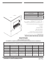
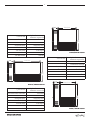
MODEL: DVN11 / DVP11
17.36" (441 mm)
20"
(508 mm)
6.61"
(168 mm)
Height 20 (508 mm)
Width 17.36 (441 mm)
Depth 6.61 (168 mm)
Weight lbs. (kg.) 28 (12.7 kg)
Type of Burner Atmospheric
# of Burners 1
Ignition Piezo-electric ignitor
Standard Heating Space
Square Feet / (m2)375 (34.8 m2)
MODEL: DVN17 / DVP17
20"
(
508 mm)
27.36" (695 mm) 6.61"
(168 mm)
Height 20 (508 mm)
Width 27.36 (695 mm)
Depth 6.61 (168 mm)
Weight lbs. (kg.) 43 (19.5 kg)
Type of Burner Atmospheric
# of Burners 1
Ignition Piezo-electric ignitor
Standard Heating Space
Square Feet / (m2)570 (52.9 m2)
MODEL: DVN25 / DVP25
26.30"
(668 mm)
32.28" (820 mm) 8.74"
(222 mm)
Height 26.30 (668 mm)
Width 32.28 (820 mm)
Depth 8.74 (222 mm)
Weight lbs. (kg.) 62.2 (28.2 kg)
Type of Burner Atmospheric
# of Burners 1
Ignition Piezo-electric ignitor
Standard Heating Space
Square Feet / (m2)825 (76.6 m2)
NOTE: A qualied service person must install the
heater. Follow all local codes. CHECK GAS TYPE! Use
only the type of gas indicated on the rating plate.
DIMENSIONS

3
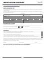
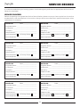
INSTALLATION CHECKLIST
Your Gas Stove should be installed by a qualied installer only. An NFI qualied Installer can be found at
www.ncertied.org/public/nd-an-n-pro/
INSTALLER CHECK LIST
This Checklist is to be completed in full by the qualied person who installs this unit. Keep this page for
future reference.
Failure to install and commission according to the manufacturer’s instructions and complete this checklist
will invalidate the warranty.
Please Print
Customer Name: Telephone Number:
Address:
Model:
Serial Number:
Installation Company Name: Phone Number:
Installation Technician’s Name: License Number:
DESCRIPTION OF WORK
Location of installed appliance: _________________________________________________________________________
Venting System: New Venting System Yes No If yes, Brand __________________________________
If no, Date of inspection of existing venting system: ______________________________________________________
CHECKLIST
Conrm clearances to combustibles as per installation instructions in this manual .................................................
Conrm the venting system is secure and sealed ...............................................................................................................................
Conrm the stove starts and operates properly ....................................................................................................................................
Check to ensure a CO alarm is installed as per local building codes and is functional .............................................
Explain the safe operation, proper fuel usage, cleaning, and routine maintenance requirements .................
Declaration of Completion: As the qualied person responsible for the work described above, I conrm that
the appliance as associated work has been installed as per manufacturer’s instructions and following any
applicable building and installation codes.
Signed: ___________________________________Print Name: ______________________________ Date: _____________
Home Owner: RETAIN THIS INFORMATION FOR FUTURE REFERENCE

4
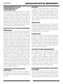
REQUIREMENTS FOR THE
COMMONWEALTH OF
MASSACHUSETTS
The following requirements reference various
Massachusetts and national codes not contained
in this manual. For all sidewall horizontally vented
gas fueled equipment installed in every dwelling,
building or structure used in whole or in part for
residential purposes, including those owned or
operated by the Commonwealth and where the
side wall exhaust vent termination is less than (7)
feet above nished grade in the area of the venting,
including but not limited to decks and porches, the
following requirements shall be satised:
INSTALLATION OF CARBON MONOXIDE
DETECTORS
At time of installation of side wall horizontally vented
gas fueled equipment, the installing plumber or
gas-tter shall observe that a hard wired carbon
monoxide detector with an alarm and battery
back-up is installed on the oor level where the
gas equipment is to be installed. In addition, the
installing plumber or gas-tter shall observe that
a battery operated or hard wired carbon monoxide
detector is installed on each additional level of the
dwelling, building or structure served by the side
wall horizontal vented gas fueled equipment. It shall
be the responsibility of the property owner to secure
the services of qualied licensed professionals for
the installation of hard wired carbon monoxide
detectors. In the event that the side wall horizontally
vented gas fueled equipment is installed in a crawl
space or attic, the hard wired carbon monoxide
detector with alarm and battery back-up may be
installed on the next adjacent oor level. In the
event that the requirements of this subdivision can
not be met at the time of completion of installation,
the owner shall have a period of thirty (30) days to
comply with the above requirements; provided,
however, that during said thirty (30) day period, a
battery operated carbon monoxide detector with
an alarm shall be installed.
APPROVED CARBON MONOXIDE
DETECTORS
Each carbon monoxide detector as required in
accordance with the above provisions shall comply
with NFPA 720 and be ANSI/UL 2034 listed and IAS
certied.
SIGNAGE
A metal or plastic identication plate shall be
permanently mounted to the exterior of the
building at a minimum of eight (8) feet above
grade directly in line with the exhaust vent terminal
for the horizontally vented gas fueled heating the
appliance or equipment. The sign shall read, in
print no less the one-half inch (1/2”) in size, “GAS
VENT DIRECTLY BELOW. KEEP CLEAR OF ALL
OBSTRUCTIONS”.
INSPECTION
The state or local gas inspector of the side wall
horizontally vented gas fueled equipment shall not
approve the installation unless, upon inspection, the
inspector observes carbon monoxide detectors and
signage installed in accordance with the provisions
of 248 CMR 5.08 (2) (a) 1 through 4.
EXEMPTIONS
The following equipment is exempt from 248 CMR
5.08 (2) (a) 1 through 4: The equipment listed in
Chapter 10 entitled “Equipment Not Required To
Be Vented” in the most current edition of NFPA 54
as adopted by the Board; and Product Approved
side wall horizontally vented gas fueled equipment
installed in a room or structure separate from the
dwelling, building or structure used in whole or in
part for residential purposes.
MANUFACTURER REQUIREMENTS
Gas Equipment Venting System Provided: When
the manufacturer of Product Approved side wall
horizontally vented gas equipment provides
a venting system design or venting system
components with the equipment, the instructions
provided by the manufacturer for installation of the
equipment and the venting system shall include:
Detailed instructions for the installation of the
venting system design or the venting system
components; and a complete parts list for the
venting system design or venting system.
GAS EQUIPMENT VENTING SYSTEM NOT
PROVIDED
When the manufacturer of Product Approved side
wall horizontally vented gas equipment does not
provide the parts for venting the ue gases, but
identies “special venting systems”, the following
requirements shall be satised by the manufacturer:
MASSACHUSETTS RESIDENTS

5
MASSACHUSETTS RESIDENTS
The referenced “special venting systems”
instructions shall be included with the appliance or
equipment installation instructions and;
The “special venting systems” shall be Product
Approved by the Board, and the instructions for
that system shall include a parts list and detailed
installation instructions.
A copy of all installation instructions for all Product
Approved side wall horizontally vented gas fueled
equipment, all venting instructions, all parts lists
for venting instructions, and/or all venting design
instructions shall remain with the appliance or
equipment at the completion of the installation.
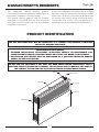
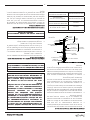
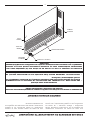
VIEW PORT
CABINET BACK
IGNITOR CONTROL KNOB
GRILL GUARD
FRONT PANEL
PRODUCT IDENTIFICATION
THIS GAS APPLIANCE MUST NOT BE CONNECTED TO A CHIMNEY FLUE SERVING A SEPARATE
SOLID-FUEL BURNING APPLIANCE.
DO NOT USE THIS APPLIANCE IF ANY PART HAS BEEN UNDER WATER. IMMEDIATELY CALL A
QUALIFIED SERVICE TECHNICIAN TO INSPECT THE APPLIANCE AND TO REPLACE ANY PART OF
THE CONTROL SYSTEM AND ANY GAS CONTROL WHICH HAS BEEN UNDER WATER.
IMPORTANT FOR YOUR SAFETY
• IMPROPER INSTALLATION, ADJUSTMENT, ALTERATION, SERVICE, OR MAINTENANCE CAN
CAUSE PROPERTY DAMAGE, PERSONAL INJURY OR LOSS OF LIFE. REFER TO THIS MANUAL.
• INSTALLATION AND SERVICE MUST BE PERFORMED BY A QUALIFIED INSTALLER, SERVICE
AGENCY, OR THE GAS SUPPLIER.

6
INSTALLATION
INSTALLATION ITEMS
Before installing heater, make sure you have the
items listed below.
• Piping (check local codes)
• Sealant (resistant to propane gas)
• Manual shutoff valve
• Ground joint union
• Sediment trap
• Tee joint
• Pipe wrench
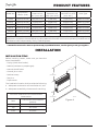
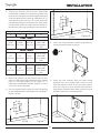
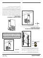
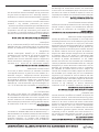
The installation location shall provide the following:
a. Adequate combustion and ventilation air, and
b. Adequate accessibility clearances for servicing.
Minimum Clearance From Combustible
Construction
Rear 0.25 inches (with supplied
spacers)
Sides 6 inches
Top 36 inches
Floor 6 inches
Figure 4
CEILING
36”
(914 mm) Min.
6”
(152 mm) Min.
6”
(152 mm) Min. FLOOR
PRODUCT FEATURES
Model No. Input Power *
Btu/Hr. (kW)
Max. Gas Inlet
Pressure inch
W.C. (mm. W.C.)
Min. Gas Inlet
Pressure inch
W.C. (mm. W.C.)
Pres. Reg. Settings
Manifold inch W.C.
(mm. W.C.)
Valve Type
DVN11 11,000 (3.20 kW) 10.5 (267 mm) 7 (178 mm) 5 (127 mm) Chant RTZ-WK
DVP11 11,000 (3.20 kW) 14 (355 mm) 11 (280 mm) 10 (254 mm) Chant RTZ-WK
DVN17 17,000 (4.94 kW) 10.5 (267 mm) 7 (178 mm) 5 (127 mm) Chant RTZ-WK
DVP17 17,000 (4.94 kW) 14 (355 mm) 11 (280 mm) 10 (254 mm) Chant RTZ-WK
DVN25 25,000 (7.33 kW) 10.5 (267 mm) 7 (178 mm) 5 (127 mm) Chant RTZ-WK
DVP25 25,000 (7.33 kW) 14 (355 mm) 11 (280 mm) 10 (254 mm) Chant RTZ-WK
**NOTE: Minimum Gas Inlet Pressure for purpose of input adjustment. The efciency rating of the
appliance is a product thermal efciency rating determined under continuous operating conditions and
was determined independently of any installed system.
* Installation and service must be performed by a qualied installer, service agency or the gas supplier *

7
INSTALLATION
£
>
£
>
£
>
£
>
£
>
>
£
>
£
>
†
‡
E
A
A
H
H
I
K
J
X
X
C
F
INSIDE
CORNER DETAIL
FIXED
CLOSED FIXED
CLOSED
OPERABLE
OPERABLE
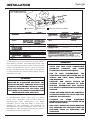
VENT TERMINAL
X
AIR SUPPLY INLET AREA WHERE TERMINAL IS NOT PERMITED
This appliance may be installed in an aftermarket,
permanently located, manufactured home (USA
only) or mobile home, where not prohibited by local
codes. This appliance is only for use with the type
of gas indicated on the rating plate. This appliance
is not convertible for use with other gases, unless a
certied kit is used.
IMPORTANT:
THIS APPLIANCE SHOULD ONLY BE
INSTALLED BY A QUALIFIED INSTALLER. THE
INSTALLATION MUST CONFORM WITH LOCAL
CODES OR, IN THE ABSENCE OF LOCAL CODES,
WITH THE NATIONAL FUEL GAS CODE, ANSI
Z223.1/NFPA 54, NATURAL GAS AND PROPANE
INSTALLATION CODE, CSA B149.1.
A manufactured home (USA only) or mobile
home OEM installation must conform with the
Manufactured Home Construction and Safety
Standard, Title 24 CFR, Part 3280, or, when such
standard is not applicable, the Standard for
Manufactured Home Installations, ANSI Z 225.1, or
Standard for Gas Equipped Recreational Vehicles
and Mobile Housing, CSA Z 240.4.
IMPORTANT:
• THE APPLIANCE AREA MUST BE KEPT
CLEAR AND FREE FROM COMBUSTIBLE
MATERIALS, GASOLINE, AND OTHER
FLAMMABLE VAPORS AND LIQUIDS.
• DUE TO HIGH TEMPERATURES, THE
APPLIANCE SHOULD BE LOCATED OUT OF
TRAFFIC AND AWAY FROM FURNITURE
AND DRAPERIES.
• CHILDREN AND ADULTS SHOULD BE
ALERTED TO THE HAZARDS OF HIGH
SURFACE TEMPERATURE AND SHOULD
STAY AWAY TO AVOID BURNS OR CLOTHING
IGNITION.
• YOUNG CHILDREN SHOULD BE CAREFULLY
SUPERVISED WHEN THEY ARE IN THE SAME
ROOM AS THE APPLIANCE.
• CLOTHING OR OTHER FLAMMABLE
MATERIAL SHOULD NOT BE PLACED ON OR
NEAR THE APPLIANCE.
• ANY SAFETY SCREEN OR GUARD REMOVED
FOR SERVICING AN APPLIANCE MUST BE
REPLACED PRIOR TO OPERATING THE
APPLIANCE.

8
INSTALLATION
IMPORTANT:
INSTALLATION AND REPAIR SHOULD BE
DONE BY A QUALIFIED SERVICE PERSON.
THE APPLIANCE SHOULD BE INSPECTED
BEFORE USE AND AT LEAST ANNUALLY
BY A QUALIFIED SERVICE PERSON. MORE
FREQUENT CLEANING MAY BE REQUIRED
DUE TO EXCESSIVE LINT FROM CARPETING,
BEDDING MATERIAL, ETC. IT IS IMPERATIVE
THAT CONTROL COMPARTMENTS, BURNERS
AND CIRCULATING AIR PASSAGEWAYS OF
THE APPLIANCE BE KEPT CLEAN.
WARNING:
FAILURE TO POSITION THE PARTS IN
ACCORDANCE WITH THESE DIAGRAMS, OR
FAILURE TO USE ONLY PARTS SPECIFICALLY
APPROVED WITH THIS APPLIANCE MAY
RESULT IN PROPERTY DAMAGE OR PERSONAL
INJURY.
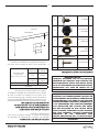
HARDWARE PACKET CONTENTS
KEY DESCRIPTION ITEM QTY
iMedium Screw 3
ii Large Screw 4
iii Washer 4
iv Spacer Washer 4
vRubber
Grommet 2
vi Small Screw 8
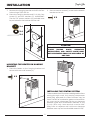
INSTALLING THE APPLIANCE
Separate the hanging bracket from the appliance
by removing two screws on the top and two nuts at
the bottom.
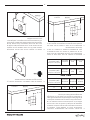
INSTALLING THE HANGING BRACKET
ON A NON-COMBUSTIBLE WALL ( I.E.,
MASONRY BLOCK OR CONCRETE)
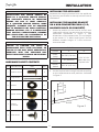
1. Draw the position of the hole for the air-vent
intake pipe, taking into account the minimum
clearances mentioned in gure 4. See
dimensions of the square hole “D” and height
to the center “C” in table 1 and gure 5 for the
different models. Height “C” is the minimum
recommended.
TABLE 1
MODEL CD
DVN11 -
DVP11 20-7/32” (514 mm)
11-1/4” X 11-1/4”
(286 x 286 mm)
square hole
DVN17 -
DVP17 20” (508 mm)
DVN25 -
DVP25 25-7/16” (647 mm)
2. Cut the square hole through the wall according
to the measurements and positions indicated
in gure 5.
C
FLOOR
D
D
Figure 5

9
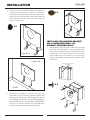
3. Insert the two provided rubber grommets (v)
into the lower bracket as shown in gure 6a.
Place the hanging bracket over the square hole.
Check to see the bracket is level. After leveling
the hanging bracket, mark the four holes as
shown in gure 6b.
v
Figure 6a
X 2
FLOOR
Figure 6b
4. Remove the hanging bracket and drill the
four holes using a masonry drill bit. NOTE: The
masonry drill bits size must match the size of
the masonry screw that will be used (masonry
screws and drill bit not included). IMPORTANT:
The four 1/4” spacer washers (iv) provided must
be put between the bracket and the wall.
FLOOR
iv
X 4
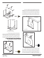
INSTALLING THE HANGING BRACKET
ON A COMBUSTIBLE WALL (I.E,
DRYWALL/WOODEN WALL)
1. Remove the required heat shield from the box
and fold it as indicated in the illustration (fold
along the perforated lines and break off when
installing in a 2 X 4 wall). Align the holes on the
heat shield with the holes on the mounting
bracket and attach using the six provided small
screws (vi).
HEAT SHIELD
Perforated Line for 2X4
Installation
vi
X 6
INSTALLATION

10
2. Taking into account the minimum clearances
mentioned in table two, locate the closest wall
stud (which will serve to hold the appliance) and
mark the square hole center at a distance “A”, (if
wall stud is at the right), or “B”, (if the stud is at
the left)(see table 2 and Figures 7 and 8). Note:
Use the heat shield to help hold the bracket in
place when marking the square hole locations.
TABLE 2
A B C D
DVN11 / DVP11
9-1/8”
(233 mm)
6-13/16”
(174 mm)
20-3/16”
(514 mm)
11-1/4” X 11-1/4”
(286 x 286
mm) square
hole
DVN17 / DVP17
8”
(204 mm)
8”
(204 mm)
19-1/2”
(495 mm)
11-1/4” X 11-1/4”
(286 x 286
mm) square
hole
DVN25 / DVP25
8”
(204 mm)
8”
(204 mm)
23-3/16”
(590 mm)
11-1/4” X 11-1/4”
(286 x 286
mm) square
hole
3. Draw the position of the square hole for the
vent-air intake pipe (see dimensions for square
hole “D” and the height to the center “C” in
table 2 for the different models. Height “C” is the
minimum recommended.
4. Cut the square hole through the wall according
to the measurements and positions indicated in
gure 7 and 8.
C
FLOOR
D
D
A
Figure 7
C
FLOOR
D
D
B
Figure 8
5. Insert the two provided rubber grommets (v)
into the lower bracket as shown.
v
X 2
6. Place the wall bracket with the heat shield
attached into the square hole. Check to see
that the bracket is level. If not, you may have to
trim the hole you cut to ensure the bracket is
level when installed. After leveling the hanging
bracket, mark the 4 holes as shown.
FLOOR
INSTALLATION

11
7. Remove the hanging bracket and drill the four
holes using a 3/32” drill bit.
8. Place the hanging bracket and x it with four
screws (ii) and four washers (iii). IMPORTANT:
The four 1/4” spacer washers (iv) provided must
be put between the bracket and the wall.
FLOOR
ii
iii
iv
X 4
X 4
X 4
MOUNTING THE HEATER ON HANGING
BRACKET
1. Place the heater on the hanging bracket and
secure with two small screws (vi).
vi
X 2
2. Use two medium screws (i) to secure the bottom
bracket to the unit.
i
X 2
ATTENTION:
THE ATTACHED SET OF THREE MARKING
PLATES (RATING PLATE, OPERATION
INSTRUCTIONS, AND SAFETY PLATE) MUST
NOT BE REMOVED FROM THE APPLIANCE AT
ANY TIME.
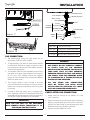
INSTALLING THE VENTING SYSTEM
These models of wall furnaces are designed for direct
venting through a wall. Only venting components
specically approved for these furnaces may be
used. The ow of combustion gases and ventilation
air must not be obstructed. Minimum clearance
between pipes and combustible materials is one
(1) inch (25.4 mm). Vent terminal must be 18.0”
away from an adjacent wall. Minimum clearance
between vent cap and combustible material 1-3/4”.
INSTALLATION

12
IMPORTANT:
THE VENT-AIR INTAKE SYSTEM MUST BE
PROPERLY INSTALLED TO ENSURE PROPER
AND SAFE OPERATION. THE VENT-AIR
INTAKE SYSTEM MUST ALSO BE PROPERLY
RE-INSTALLED AND RESEALED TO ENSURE
PROPER AND SAFE OPERATION.
WARNING:
FAILURE TO POSITION THE PARTS IN
ACCORDANCE WITH THESE DIAGRAMS OR
FAILURE TO USE ONLY PARTS SPECIFICALLY
APPROVED WITH THIS APPLIANCE MAY
RESULT IN PROPERTY DAMAGE OR PERSONAL
INJURY.
IMPORTANT:
THE APPLIANCE’S VENTING SYSTEM SHOULD
BE INSPECTED AT LEAST ONCE A YEAR AND
IMMEDIATELY CLEANED IF NECESSARY.
CAUTION:
ALL JOINTS MUST BE AIR-TIGHT.
CAUTION:
THE VENT PIPE MUST HAVE A SLIGHT
DOWNWARD SLOPE. 1/4” PER FOOT.
The venting system consists of:
A Vent Cap
B Vent Pipe
C Vent-Air Intake Pipe
D Rod
E Nut
F Outdoor Mounting Plate
GSilicon-Rubber Ring
H Tape
i Insulation
Table 3 Lengths Of Pipes And Rod.
Vent Pipe (B) Vent-Air Intake
Pipe (C) Rod (D)
Wall Thickness
+ 3-3/8“
(86 mm)
Wall Thickness
+ 2-1/2“
(64 mm)
Wall Thickness
+ 5-7/8“
(149.5 mm)
A
E
G
FB
CHi
D
Figure 12
*
Minimum of
4-1/2” (115 mm)
Wall Thickness
Maximum of
10” (254 mm)
Wall Thickness
*
Figure 13
Measure thickness of the wall as shown in gure 13.
1. If any of the following are long trim them
according to thickness of the wall, (see table 3):
• (B) vent pipe
• (C) vent-air intake pipe
• (i) insulation
• (D) rod
2. The hole at the outside of the wall must be a
square of 11-1/4” (286 mm) X 11-1/4” (286 mm) (see
gure 15).
3. From the outside of the wall, screw the rod
(D) slightly onto support located inside the
appliance ue outlet.
4. Wrap the vent-air intake pipe (C) with the
provided insulation (i) (foil side out) and place
the provided strip of tape (H) down the seam to
secure it.
INSTALLATION

13
5. Slide the smaller vent pipe (B) (from outside
your house) through the hole in the wall and
attach to the mounted heater inside your house.
Be sure the vent pipe is snug and engaged to
the heater. Then slide the larger Vent‐Air Intake
Pipe, with the insulation wrapped and taped to
the outside of the pipe, through the same hole
and over the smaller Vent Pipe (B) and attach to
the heater.
NOTE: It is critical that the insulation wrap (i) be
wrapped and secured with the tape on the outside
of the larger Vent‐Air Intake Pipe (C). The insulation
is NOT to be wrapped in between Vent Pipe (B) and
Vent‐Air Intake Pipe (C) (see gure 14).
Rod (D)
Vent Pipe (B)
V
ent-Air
Int
ake Pipe (C)
Insula�on
Wrap (i)
Figure 14
6. The outdoor mounting plate (F) and the silicon-
rubber ring (G) should be installed between
the vent cap (A) and the exterior wall. Note: For
additional security the outdoor mounting plate
(F) can be attached to the outside of the wall
using the appropriate hardware for mounting
to the surface of the building. The outdoor
mounting plate (F) must be positioned ush
to the wall and sealed with a non-hardening
mastic (silicone caulk). Position the outdoor
mounting plate (F) so that the vent-air intake
pipe (C) has a slight downward slope of 1/4” per
foot of venting to the outside.
ATTENTION:
THE DOWNWARD SLOPE IS NECESSARY TO
PREVENT THE ENTRY OF RAINWATER.
7. Before attaching the vent cap (A) to the exterior
wall, run a bead of non-hardening mastic
(silicone caulk) around its outside edge, so
as to make a seal between it and the outdoor
mounting plate (F) (see gure 16).
8. Slide the vent cap (A) into position and secure
into place using the provided nut (E). Tighten
nut (E) down until the vent cap (A) leans against
the outdoor mounting plate (F) (see gures 15
and 16).
11-1/4" (286mm) x 11-1/4" (286mm)
square hole
Heat Shield
Figure 15
11-1/4" (286mm) x 11-1/4" (286mm)
square hole
Heat Shield
REQUIRED:
Downward slope
of 1/4” per foot
of venting to the
outside
Flush with
Mastic
Figure 16
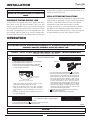
INSTALLING THE THERMOSTAT SENSOR
In order to protect the thermostat sensor from
any damage during shipping, or while handling
it before it is denitely installed, the thermostat
sensor has not been attached to its nal location in
the appliance. So, once the heater is installed, the
thermostat sensor must be placed and secured in
position. To do so, follow these steps:
1. Reach in through the bottom of the unit and
cut the cable tie holding the thermostat sensor
to the unit.
2. Place the thermostat sensor under the right
bottom of the bracket and attach it with
the provided medium screw (i) that xes the
appliance to the bracket as shown in gures 17
and 18.
INSTALLATION

14
Figure 17
Figure 18
SCREW
BRACKET
i
x 1
Figure 17
Figure 18
SCREW
BRACKET
i
x 1
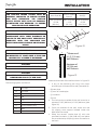
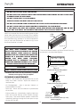
GAS CONNECTION
1. We recommend using only new black iron or
steel pipe. CHECK LOCAL CODES.
2. The gas supply line shall be sized and installed
to provide a sufcient supply of gas to meet
the maximum demand of the heater without
undue loss of pressure.
3. The sealant used on the threaded joints of the
gas pipe must be a type resistant to the action
of L.P. Gas. (This sealant should be applied
lightly to main threads to ensure excess sealant
does not enter lines.)
4. The supply system must include a manual
shut off valve and connection in the line, so the
heater can be disconnected for servicing. (See
Figure 18).
5. Include a drip leg (trap) and a plugged 1/8”
N.P.T. tapping in the line. The tapping should be
accessible for test gauge connections upstream
of the gas supply connection to the heater.
IMPORTANT:
HOLD THE GAS INLET OF THE APPLIANCE
WITH WRENCH WHEN CONNECTING IT TO
GAS PIPING AND/OR FITTINGS.
3/8” NPT PIPE NIPPLE
PIPE NIPPLE
1/8” NPT PLUG TAP
REDUCER BUSHING
TO 1/8” NPT
SEDIMENT
TRAP
TEST GAUGE
CONNECTION
TEE JOINT
TEE JOINT
CLOSED
OPEN GROUND JOINT UNION
APPLIANCE GAS INLET
FROM GAS METER
3 (76.2 MM)
MINIMUM
CAP
MANUAL SHUTOFF
VALVE
Figure 19
Pressure
Nat. Gas 7” W.C to 10.5” W.C.
Nat. Gas 178 mm W.C. to 267 mm W.C.
L.P. Gas 11” W.C. to 14” W.C.
L.P. Gas 280 mm W.C. to 356 mm W.C.
WARNING:
• FOR L.P. GAS, USE PRESSURE REGULATED
GAS SUPPLY. DO NOT DIRECTLY CONNECT
LP SUPPLY TANK TO THE PRESSURE
REGULATOR ON THE HEATER. THE LP SUPPLY
TANK MUST HAVE ITS OWN SEPARATE
PRESSURE REGULATOR THAT CAN REDUCE
THE SUPPLY TANK GAS PRESSURE DOWN
TO A MAXIMUM OF 14 INCHES (355 MM) OF
WATER COLUMN PRESSURE.
• ALL GAS PIPING AND CONNECTIONS
MUST BE TESTED FOR LEAKS AFTER
INSTALLATION OR SERVICING. ALL LEAKS
MUST BE CORRECTED IMMEDIATELY.
CHECK AFTER GAS CONNECTION
1. Make sure the control of the heater is in the
“OFF” position.
2. Open the manual shut off valve. Test for leaks by
applying liquid detergent to all joints. Check all
joints from gas meter to thermostat gas valve.
(Bubbles forming indicate a gas leak)
3. Correct any leak defect at once.
INSTALLATION

15
INSTALLATION
CAUTION:
NEVER USE AN OPEN FLAME TO CHECK FOR
LEAKS
PRESSURE TESTING SUPPLY LINE
ATTENTION: This appliance and its appliance main
gas valve must be disconnected from the gas
supply piping system during any pressure testing
of that system at test pressures in excess of 1/2 psi
(3,5 kPa). The appliance must be isolated from the
gas supply piping system by closing equipment
shutoff valve during any pressure testing of the gas
supply piping system at test pressures equal to or
less than 1/2 psi (3,5 kPa).
HIGH ALTITUDE INSTALLATIONS
This appliance may be installed at higher altitudes.
Please refer to National Fuel Gas Code ANSI Z223.1/
NFPA 54, CSA-B149.1 Natural Gas and Propane
Installation Code, local authorities, or codes
having jurisdiction in your area regarding derate
guidelines. Per the above referenced codes, for
elevations above 2,000 ft (610 m), input ratings are
to be reduced by 4% for each 1,000 ft (305 m).
OPERATION
damage, personal injury or loss of life.
1. Set thermostat to lowest setting. (If applicable).
2. Turn control knob clockwise to the "OFF" position. Do not Force.
CAUTION:Wait five (5) minutes before re-lighting heater.
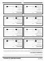
LIGHTING INSTRUCTIONS
TO TURN OFF GAS TO APPLIANCE
1. STOP! Read the safety information on the attached plate.
2. Check that gas supply to heater is on.
3. Set the thermostat to the lowest setting. (If applicable).
4. Push in gas control knob slightly and turn clockwise
to "OFF" position. Do not force.
NOTE: Knob cannot be turned from "PILOT" to "OFF"
unless knob is pushed in slightly. Do not force.
5. Wait five (5) minutes to clear out any gas. If you then
smell gas, STOP! Follow "B" in the safety information
above this label. If you don't smell gas, go to the next
step.
6. Find pilot. The pilot can be seen through the view port on
the top of the appliance.
7. Turn gas control knob counterclockwise to "PILOT".
Keep control knob depressed and continuously push the
white piezo button. This should cause the spark from the
ignitor to light the pilot gas. Keep control knob depressed
for ten (10) seconds before releasing. If Pilot does not
light, repeat step 6. NOTE: It may be necessary to press
for thirty (30) seconds if this is first time heater is
connected to the gas supply.If the knob does not pop up
when released, stop and immediately call your service
technician or gas supplier. If the pilot will not stay lit after
several tries, turn the gas control knob to "OFF" and call
your service technician or gas supplier.
8. When pilot is lit, turn the control knob counterclockwise
to desired heating level.
9. Set thermostat to desired setting. (If applicable).
853265
Model DVAG 11, DVAG17 and 30
POSITION INDICATOR
Pliot Burner
Model DVAG11, DVAV17 and 30
WARNING:
IF YOU DO NOT FOLLOW THESE INSTRUCTIONS EXACTLY, A FIRE EXPLOSION MAY RESULT CAUSING
PROPERTY DAMAGE, PERSONAL INJURY OR LOSS OF LIFE.
CAUTION:
DO NOT TRY TO ADJUST HEATING LEVELS BY USING THE MANUAL SHUTOFF VALVE.

16
IMPORTANT:
• DO NOT DRY CLOTHES OVER THE HEATER.
• DO NOT SPRAY ANY AEROSOL NEAR THE HEATER WHEN FUNCTIONING. DO NOT STORE THESE
ELEMENTS NEAR THE APPLIANCE.
• DO NOT TOUCH GRILL TO AVOID BURNS.
• AVOID BLOCKING AIR INLET AND HOT AIR OUTLET.
• DO NOT SPILL WATER OVER THE HEATER AS IT MAY CAUSE CORROSION OR DAMAGE.
• DO NOT TOUCH VENT CAP WHILE HEATER IS OPERATING, TO AVOID BURNS.
• IF YOU SMELL GAS, SHUT OFF CONTROL VALVE, OPEN DOORS AND WINDOWS AND DO NOT
LIGHT ANY ELECTRICAL FIXTURE NEAR THE HEATER. CALL YOUR GAS SUPPLIER.
NOTE: It is normal for the new wall furnace to give
some odor the rst time it is burned. This is due to
the curing of the paint and any undetected oil from
the manufacturing process. It is recommended to
burn a new wall furnace for at least two (2) hours
the rst time that it is used.
CAUTION:
YOU MUST KEEP CONTROL AREAS AND
CIRCULATING AIR PASSAGEWAYS OF HEATER
CLEAN. INSPECT THESE AREAS OF HEATER
BEFORE EACH USE. HAVE HEATER INSPECTED
YEARLY BY A QUALIFIED SERVICE PERSON.
HEATER MAY NEED MORE FREQUENT
CLEANING DUE TO EXCESSIVE LINT FROM
CARPETING, BEDDING MATERIAL, ETC. VERIFY
PROPER OPERATION AFTER SERVICING.
ATTENTION:
VERIFY PROPER OPERATION AFTER SERVICING
* Installation and service must be performed by a qualied
installer, service agency or the gas supplier *
CLEANING & MAINTENANCE
• Exterior - Use a soft cloth dampened with a mild
soap and water mixture. Wipe the cabinet to
remove dust.
• Air Passageways - Use a vacuum cleaner or
pressurized air to clean.
• Vent Cap - Use a vacuum cleaner or pressurized
air to clean.
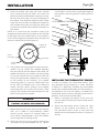
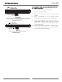
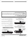
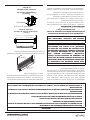
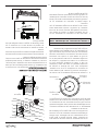
• Pilot and Burner - Periodically visually check the
pilot and burner ames (view ames through
view port). The correct ame pattern should be
viewed by looking through the view port on top
of the unit (Fig. 20).
VIEW
PORT
Figure 20
The correct ame pattern of pilot and main burner
are shown in the provided gures.
PRIMARY FLAME: 1/4´´ - 3/8´´ (6 - 10 mm)
SECONDARY FLAME: 2´´ - 4´´ (50 - 100 mm)
Figure 21
Correct main burner flame pattern
THERMOCOUPLE
PILOT FLAME
Figure 22
Correct pilot burner flame pattern
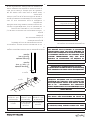
Figure. 23
Correct main burner flame pattern (top view)
Models DV(N)(P)11
SECONDARY FLAME
PRIMARY FLAME
THERMOCOUPLE
PILOT FLAME
Figure. 25
Correct main burner flame pattern (top view)
Model DV(N)(P)25
SECONDARY FLAME
PRIMARY FLAME
PILOT FLAME
THERMOCOUPLE
Figure. 24
Correct main burner flame pattern (top view)
Models DV(N)(P) 17
SECONDARY FLAME
PRIMARY FLAME
PILOT FLAME
THERMOCOUPLE
PRIMARY FLAME: 1/4´´ - 3/8´´ (6 - 10 mm)
SECONDARY FLAME: 2´´ - 4´´ (50 - 100 mm)
Figure 21
Correct main burner flame pattern
THERMOCOUPLE
PILOT FLAME
Figure 22
Correct pilot burner flame pattern
Figure. 23
Correct main burner flame pattern (top view)
Models DV(N)(P)11
SECONDARY FLAME
PRIMARY FLAME
THERMOCOUPLE
PILOT FLAME
Figure. 25
Correct main burner flame pattern (top view)
Model DV(N)(P)25
SECONDARY FLAME
PRIMARY FLAME
PILOT FLAME
THERMOCOUPLE
Figure. 24
Correct main burner flame pattern (top view)
Models DV(N)(P) 17
SECONDARY FLAME
PRIMARY FLAME
PILOT FLAME
THERMOCOUPLE
OPERATION

17
OPERATION
PRIMARY FLAME: 1/4´´ - 3/8´´ (6 - 10 mm)
SECONDARY FLAME: 2´´ - 4´´ (50 - 100 mm)
Figure 21
Correct main burner flame pattern
THERMOCOUPLE
PILOT FLAME
Figure 22
Correct pilot burner flame pattern
Figure. 23
Correct main burner flame pattern (top view)
Models DV(N)(P)11
SECONDARY FLAME
PRIMARY FLAME
THERMOCOUPLE
PILOT FLAME
Figure. 25
Correct main burner flame pattern (top view)
Model DV(N)(P)25
SECONDARY FLAME
PRIMARY FLAME
PILOT FLAME
THERMOCOUPLE
Figure. 24
Correct main burner flame pattern (top view)
Models DV(N)(P) 17
SECONDARY FLAME
PRIMARY FLAME
PILOT FLAME
THERMOCOUPLE
CLEANING THE MAIN BURNER ORIFICE
& MAIN BURNER
1. Turn OFF gas supply to the heater.
2. Remove casing assembly.
3. Disconnect burner tubing and remove orice
holder.
4. Apply compressed air to the orice holder
assembly to remove dust, lint or spider webs.
5. Apply compressed air through the hole on the
combustion chamber wall where the orice
holder was originally located to remove dust,
lint or spider webs.
6. As parts are being replaced in reverse order,
check for gas leaks at all gas connections before
replacing the casing assembly.

18
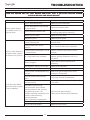
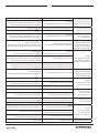
PROBLEM POSSIBLE CAUSE REMEDY
When ignitor button
is pressed, there is no
spark at pilot.
Ignitor electrode broken. Replace ignitor electrode.
Ignitor electrode not connected
to ignitor cable. Reconnect ignitor cable.
Ignitor cable pinched or wet. Free ignitor cable if pinched by any metal
or tubing. Keep ignitor cable dry.
Broken ignitor cable. Replace ignitor cable.
Bad piezo ignitor. Replace piezo ignitor.
When ignitor button is
pressed, there is spark
at pilot but no ignition.
Gas supply is turned off or manual
shutoff valve closed.
Turn on gas supply or open manual
shutoff valve.
Control knob not in PILOT
position. Turn control knob to PILOT position.
Control knob not pressed in while
in pilot position.
Press in control knob while in PILOT
position.
Air in gas lines when installed.
Continue holding down control knob.
Repeat igniting operation until air is
removed.
Pilot is clogged. Clean pilot orice or replace pilot
assembly.
Gas regulator setting not correct. Replace gas regulator.
Pilot lights but ame
goes out when control
knob is released.
Control knob not fully pressed in. Press in control knob fully.
Control knob not depressed long
enough.
After pilot lights, keep control knob
pressed in 30 seconds.
Manual shutoff valve not fully
open. Fully open manual shutoff valve.
Thermocouple connection loose
at control valve.
Hand tighten until snug, then tighten 1/4
turn more.
Pilot ame not touching
thermocouple, which allows
thermocouple to cool, causing
pilot ame to go out. This
problem could be caused by one
or both of the following:
Low gas pressure.
Dirty or partially clogged pilot.
Contact local gas company.
Clean pilot or replace pilot assembly.
Thermocouple damaged. Replace thermocouple.
Control valve damaged. Replace control valve.
TROUBLESHOOTING
WARNING:
TURN OFF HEATER AND LET COOL BEFORE SERVICING. ONLY A QUALIFIED SERVICE PERSON
SHOULD SERVICE AND REPAIR HEATER.

19
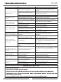
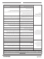
PROBLEM POSSIBLE CAUSE REMEDY
Burner does not light
after pilot is lit.
Burner orice is clogged. Clean burner orice or replace burner
orice.
Burner orice diameter is too
small. Replace burner orice.
Inlet gas pressure is too low. Contact local Gas Company.
Delayed ignition of
burner.
Manifold pressure is too low. Contact local Gas Company.
Burner or pilot orice is clogged. Clean burner or pilot orice or replace it.
Burner backring
during combustion.
Burner orice is clogged or
damaged. Clean burner orice or replace it.
Gas regulator defective. Replace gas regulator.
Yellow ame during
burner combustion.
Inlet pipe is blocked. Remove the blockage.
Incorrect connections of pipes. Connect pipes according to installation
instructions.
Gas regulator defective. Replace gas regulator.
Slight smoke or odor
during initial operation.
Residues from manufacturing
processes.
Problem will stop after a while of
operation.
Heater produces a
whistling noise when
burner is lit.
Turning control knob to HI
position when burner is cold.
Turn control knob to LO position and let
warm up for a minute.
Air in gas line.
Operate burner until air is removed from
line. Have gas line checked by local Gas
Company.
Dirty or partially clogged burner
orice. Clean burner orice or replace it.
Heater produces a
clicking/ticking noise
just after burner is lit or
shut off.
Metal expanding while heating or
contracting while cooling.
This is common with most heaters. If noise
is excessive, contact qualied service
person.
Heater produces
unwanted odors.
Gas leak (see WARNING
statement below).
Locate and correct all leaks (see Checking
Gas Connections section)
Heater shuts off in use. Low line pressure. Contact local Gas Company.
Pilot is partially clogged. Clean pilot.
Gas odor even when
control knob is in OFF
position.
Gas leak. See WARNING
statement below.
Locate and correct all leaks (see Checking
Gas Connections section)
Control valve defective. Replace control valve.
TROUBLESHOOTING
WARNING IF YOU SMELL GAS:
• SHUT OFF GAS SUPPLY.
• DO NOT TRY TO LIGHT ANY APPLIANCE
• DO NOT TOUCH ANY ELECTRICAL SWITCH, DO NOT USE ANY PHONE IN YOUR BUILDING.
• IMMEDIATELY CALL YOUR GAS SUPPLIER FROM A NEIGHBOR’S PHONE. FOLLOW THE GAS
SUPPLIER’S INSTRUCTIONS.
• IF YOU CANNOT REACH YOUR GAS SUPPLIER, CALL THE FIRE DEPARTMENT.

20
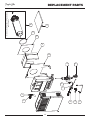
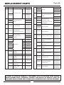
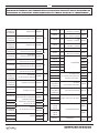
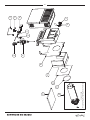
REPLACEMENT PARTS
3
4
5
6
9
7
8
1
2
13
15
10
11
14
12
Includes: Inner Pipe, Outer Pipe, Vent Cap,
Rod and Nut.
La page est en cours de chargement...
La page est en cours de chargement...
La page est en cours de chargement...
La page est en cours de chargement...
La page est en cours de chargement...
La page est en cours de chargement...
La page est en cours de chargement...
La page est en cours de chargement...
La page est en cours de chargement...
La page est en cours de chargement...
La page est en cours de chargement...
La page est en cours de chargement...
La page est en cours de chargement...
La page est en cours de chargement...
La page est en cours de chargement...
La page est en cours de chargement...
La page est en cours de chargement...
La page est en cours de chargement...
La page est en cours de chargement...
La page est en cours de chargement...
La page est en cours de chargement...
La page est en cours de chargement...
La page est en cours de chargement...
La page est en cours de chargement...
La page est en cours de chargement...
La page est en cours de chargement...
La page est en cours de chargement...
La page est en cours de chargement...
-
 1
1
-
 2
2
-
 3
3
-
 4
4
-
 5
5
-
 6
6
-
 7
7
-
 8
8
-
 9
9
-
 10
10
-
 11
11
-
 12
12
-
 13
13
-
 14
14
-
 15
15
-
 16
16
-
 17
17
-
 18
18
-
 19
19
-
 20
20
-
 21
21
-
 22
22
-
 23
23
-
 24
24
-
 25
25
-
 26
26
-
 27
27
-
 28
28
-
 29
29
-
 30
30
-
 31
31
-
 32
32
-
 33
33
-
 34
34
-
 35
35
-
 36
36
-
 37
37
-
 38
38
-
 39
39
-
 40
40
-
 41
41
-
 42
42
-
 43
43
-
 44
44
-
 45
45
-
 46
46
-
 47
47
-
 48
48


