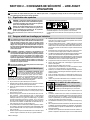
Miller TOCCOTRON AC 907690001 Manuel utilisateur
- Catégorie
- Système de soudage
- Taper
- Manuel utilisateur

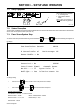
Toccotron AC
Processes
Description
Induction Heating Power Source
OM-271150L 2023-10
Visit our website at
www.AjaxTocco.com
CE
Induction Heating


TABLE OF CONTENTS
SECTION 1 − SAFETY PRECAUTIONS − READ BEFORE USING 1.................................
1-1. Symbol Usage 1.......................................................................
1-2. Induction Heating Hazards 1.............................................................
1-3. Additional Hazards For Installation, Operation, And Maintenance 2.............................
1-4. California Proposition 65 Warnings 3......................................................
1-5. Principal Safety Standards 3.............................................................
1-6. EMF Information 3.....................................................................
SECTION 2 − CONSIGNES DE SÉCURITÉ − LIRE AVANT UTILISATION 4..........................
2-1. Signification des symboles 4.............................................................
2-2. Dangers relatifs au chauffage par induction 4...............................................
2-3. Symboles de dangers supplémentaires en relation avec l’installation,
le fonctionnement et la maintenance 5.....................................................
2-4. Proposition californienne 65 Avertissements 6..............................................
2-5. Principales normes de sécurité 6.........................................................
2-6. Informations relatives aux CEM 6.........................................................
SECTION 3 − DEFINITIONS 7..................................................................
3-1. Additional Safety Symbols And Definitions 7................................................
3-2. Miscellaneous Symbols And Definitions 9..................................................
SECTION 4 − SPECIFICATIONS 10..............................................................
4-1. Serial Number and Rating Label Location 10.................................................
4-2. Software Licensing Agreement 10.........................................................
4-3. Information About Default Weld Parameters And Settings 10...................................
4-4. Specifications 10........................................................................
4-5. Environmental Specifications 10...........................................................
SECTION 5 − INSTALLATION 12................................................................
5-1. Selecting A Location 12..................................................................
5-2. Dimensions And Weights 12..............................................................
5-3. Electrical Service Guide 13...............................................................
5-4. Connecting 3-Phase Input Power For 400/460 Volt Models 14..................................
5-5. Power Source Output Connections 16......................................................
5-6. Remote 14 Receptacle RC14 Information and Connections 17.................................
5-7. Remote 14 Socket Information 17..........................................................
5-8. I/O Receptacle RC13 Information And Connections 18........................................
5-9. I/O Receptacle RC13 Socket Information 18.................................................
SECTION 6 − COMPONENTS AND CONTROLS 19................................................
6-1. Controls 19............................................................................
SECTION 7 − SETUP AND OPERATION 20.......................................................
7-1. Safety Equipment 20....................................................................
7-2. System Description 20...................................................................
7-3. Power Source/System Setup 20...........................................................
7-4.
Programming
22........................................................................
7-5. Run Status 23..........................................................................
7-6. Parameters 24..........................................................................
7-7. Real-Time Operation 25..................................................................

TABLE OF CONTENTS
SECTION 8 − MAINTENANCE 26................................................................
8-1. Routine Maintenance 26.................................................................
SECTION 9 − SAFETY PRECAUTIONS FOR SERVICING 27........................................
9-1. Symbol Usage 27.......................................................................
9-2. Servicing Hazards 27....................................................................
9-3. California Proposition 65 Warnings 28......................................................
9-4. EMF Information 28.....................................................................
SECTION 10 − DIAGNOSTICS & TROUBLESHOOTING 29.........................................
10-1. Operator Interface Indicators 29...........................................................
10-2. Limit Conditions 29......................................................................
10-3. Limit Condition Codes 30.................................................................
10-4. Fault Conditions 30......................................................................
10-5. Fault Condition Codes 31.................................................................
10-6. System Diagnostic Screens 31............................................................
10-7. Removing Wrapper and Measuring Input Capacitor Voltage 33.................................
10-8. Blowing Out Inside Of Unit 34.............................................................
SECTION 11 − ELECTRICAL DIAGRAM 36.......................................................
SECTION 12 − PARTS LIST 38..................................................................
WARRANTY
COMPLETE PARTS LIST − Available at www.MillerWelds.com

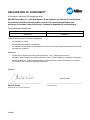
DECLARATION OF CONFORMITY
for European Community (CE marked) products.
MILLER Electric Mfg. LLC, 1635 West Spencer Street, Appleton, WI 54914 U.S.A. declares that
the product(s) identified in this declaration conform to the essential requirements and
provisions of the stated Council Directive(s), Commission Regulation(s) and Standard(s).
Product/Apparatus Identification:
Product Stock Number
Toccotron AC 907690001
Council Directives and Commission Regulations:
•2014/35/EU Low voltage
•2014/30/EU Electromagnetic compatibility
•2011/65/EU and amendment 2015/863 Restriction of the use of certain hazardous substances in electrical
and electronic equipment
Standards:
•EN IEC 60974−1:2018/A1:2019 Arc welding equipment – Part 1: Welding power sources
•EN 60974−10:2014/A1:2015 Arc welding equipment – Part 10: Electromagnetic compatibility requirements
•EN IEC 63000:2018 – Technical documentation for the assessment of electrical and electronic products
with respect to the restriction of hazardous substances
Signatory:
_____________________________________ ___________________________________________
David A. Werba Date of Declaration
MANAGER, PRODUCT DESIGN COMPLIANCE
June 24, 2021
275485C

DECLARATION OF CONFORMITY
For United Kingdom (UKCA marked) products.
MILLER Electric Mfg. LLC, 1635 West Spencer Street, Appleton, WI 54914 U.S.A. declares that
the product(s) identified in this declaration conform to the essential requirements and
provisions of the stated Regulation(s) and Standard(s).
Product/Apparatus Identification:
Product Stock Number
Toccotron AC 907690001
Regulations:
•S.I. 2016/1101 Electrical Equipment (Safety) Regulations 2016
•S.I. 2016/1091 Electromagnetic Compatibility Regulations 2016
•S.I. 2012/3032 Restriction of the Use of Certain Hazardous Substances in Electrical and
Electronic Equipment Regulations 2012
Standards:
•EN IEC 60974−1:2018/A1:2019 Arc welding equipment – Part 1 Welding power sources
•EN 60974−10:2014/A1:2015 Arc welding equipment – Part 10: Electromagnetic compatibility
requirements
•EN IEC 63000:2018 Technical documentation for the assessment of electrical and electronic
products with respect to the restriction of hazardous substances
Signatory:
_____________________________________ ___________________________________________
David A. Werba Date of Declaration
MANAGER, PRODUCT DESIGN COMPLIANCE
290553A
June 16, 2021

OM-271150 Page 1
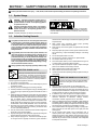
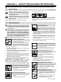
SECTION 1 − SAFETY PRECAUTIONS − READ BEFORE USING
ihom _2022-01
Protect yourself and others from injury — read, follow, and save these important safety precautions and operating instructions.
1-1. Symbol Usage
DANGER! − Indicates a hazardous situation which, if
not avoided, will result in death or serious injury. The
possible hazards are shown in the adjoining symbols
or explained in the text.
Indicates a hazardous situation which, if not avoided,
could result in death or serious injury. The possible
hazards are shown in the adjoining symbols or ex-
plained in the text.
NOTICE − Indicates statements not related to personal injury.
.Indicates special instructions.
This group of symbols means Warning! Watch Out! ELECTRIC
SHOCK, MOVING PARTS, and HOT PARTS hazards. Consult sym-
bols and related instructions below for necessary actions to avoid
these hazards.
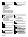
1-2. Induction Heating Hazards
The symbols shown below are used throughout this manual
to call attention to and identify possible hazards. When you
see the symbol, watch out, and follow the related instructions
to avoid the hazard. The safety information given below is
only a summary of the more complete safety information
found in the Principal Safety Standards. Read and follow all
Safety Standards.
Only qualified persons should install, operate, maintain, and
repair this equipment. A qualified person is defined as one
who, by possession of a recognized degree, certificate, or
professional standing, or who by extensive knowledge, train-
ing and experience, has successfully demonstrated the ability
to solve or resolve problems relating to the subject matter, the
work, or the project and has received safety training to recog-
nize and avoid the hazards involved.
During operation, keep everybody, especially children, away.
ELECTRIC SHOCK can kill.
Touching live electrical parts can cause fatal shocks
or severe burns. The power circuit and output bus
bars or connections are electrically live whenever
the output is on. The input power circuit and machine
internal circuits are also live when power is on. Incorrectly installed or
improperly grounded equipment is a hazard.
DDo not touch live electrical parts.
DEnclose any connecting bus bars and coolant fittings to prevent
unintentional
contact.
DWear dry, hole-free insulating gloves and body protection.
DInsulate yourself from work and ground using dry insulating mats or
covers big enough to prevent any physical contact with the work or
ground.
D
Additional
safety precautions are required when any of the following
electrically hazardous conditions are present: in damp locations or
while wearing wet clothing; on metal structures such as floors, grat-
ings, or scaffolds; when in cramped positions such as sitting,
kneeling, or lying; or when there is a high risk of unavoidable or acci-
dental contact with the workpiece or ground. For these conditions,
see ANSI Z49.1 listed in Safety Standards. And, do not work alone!
DDisconnect input power before installing or servicing this equip-
ment. Lockout/tagout input power according to OSHA 29 CFR
1910.147 (see Safety Standards).
DUse only nonconductive coolant hoses with a minimum length of 18
inches (457 mm) to provide isolation.
DProperly install, ground, and operate this equipment according to its
Owner’s Manual and national, state, and local codes.
DAlways verify the supply ground − check and be sure that input pow-
er cord ground wire is properly connected to ground terminal in
disconnect box or that cord plug is connected to a properly grounded
receptacle outlet.
DWhen making input connections, attach proper grounding
conductor first − double-check connections.
DKeep cords dry, free of oil and grease, and protected from hot metal
and sparks.
DFrequently inspect input power cord and ground conductor for dam-
age or bare wiring – replace immediately if damaged – bare wiring
can kill.
DTurn off all equipment when not in use.
DDo not use worn, damaged, undersized, or repaired cables.
DDo not drape cables over your body.
DDo not touch power circuit if you are in contact with the work, ground,
or another power circuit from a different machine.
DUse only well-maintained equipment. Repair or replace damaged
parts at once. Maintain unit according to manual.
DWear a safety harness if working above floor level.
DKeep all panels and covers securely in place.
DUse GFCI protection when operating auxiliary equipment in damp or
wet locations.
Induction Heating of certain materials, adhesives,
and fluxes can produce fumes and gases. Breathing
these fumes and gases can be hazardous to your
health.
FUMES AND GASES can be hazardous.
DKeep your head out of the fumes. Do not breathe the fumes.
DVentilate the work area and/or use local forced ventilation at the arc
to remove welding fumes and gases. The recommended way to de-
termine adequate ventilation is to sample for the composition and
quantity of fumes and gases to which personnel are exposed.
DIf ventilation is poor, wear an approved air-supplied respirator.
DRead and understand the Safety Data Sheets (SDSs) and the man-
ufacturer’s instructions for adhesives, coatings, cleaners,
consumables, coolants, degreasers, fluxes, and metals.
DWork in a confined space only if it is well ventilated, or while wearing an
air-supplied respirator. Always have a trained watchperson nearby.
Fumes and gases from heating can displace air and lower the oxygen
level causing injury or death. Be sure the breathing air is safe.
DDo not heat in locations near degreasing, cleaning, or spraying oper-
ations. The heat can react with vapors to form highly toxic and
irritating gases.
DDo not overheat coated metals, such as galvanized, lead, or
cadmium plated steel, unless the coating is removed from the
heated area, the area is well ventilated, and while wearing an air-
supplied respirator. The coatings and any metals containing these
elements can give off toxic fumes if overheated. See coating SDS
for temperature information.

OM-271150 Page 2
FIRE OR EXPLOSION hazard.
DDo not overheat parts.
DWatch for fire; keep extinguisher nearby.
DKeep flammables away from work area.
DDo not locate unit on, over, or near combustible surfaces.
DDo not use unit to thaw frozen pipes.
DDo not install unit near flammables.
DDo not cover an air−cooled blanket with any material that will
cause the blanket to overheat.
DDo not operate where the atmosphere can contain flammable
dust, gas, or liquid vapors (such as gasoline).
DAfter completion of work, inspect area to ensure it is free of
sparks, glowing embers, and flames.
DUse only correct fuses or circuit breakers. Do not oversize or by-
pass them.
DRead and understand the Safety Data Sheets (SDSs) and the
manufacturer’s instructions for adhesives, coatings, cleaners,
consumables, coolants, degreasers, fluxes, and metals.
DWear body protection made from leather or flame-resistant cloth-
ing (FRC). Body protection includes oil-free clothing such as
leather gloves, heavy shirt, cuffless trousers, high shoes, and a
cap.
INDUCTION HEATING can burn.
DDo not touch hot parts bare-handed.
DAllow cooling period before handling parts or
equipment.
DDo not touch or handle induction head/coil during operation un-
less the equipment is designed and intended to be used in this
manner as specified in the owner’s manual.
DKeep metal jewelry and other metal personal items away from
head/coil during operation.
DTo handle hot parts, use proper tools and/or wear heavy, insu-
lated welding gloves and clothing to prevent burns.
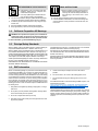
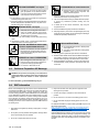
1-3. Additional Hazards For Installation, Operation, And Maintenance
FALLING EQUIPMENT can injure.
DUse lifting eye to lift unit only, NOT running
gear, gas cylinders, or any other accessories.
DUse correct procedures and equipment of ade-
quate capacity to lift and support unit.
DIf using lift forks to move unit, be sure forks are long enough to
extend beyond opposite side of unit.
DKeep equipment (cables and cords) away from moving vehicles
when working from an aerial location.
DFollow the guidelines in the Applications Manual for the Revised
NIOSH Lifting Equation (Publication No. 94−110) when manu-
ally lifting heavy parts or equipment.
FLYING METAL OR DIRT can injure eyes.
DWear approved safety glasses with side
shields or wear face shield.
MOVING PARTS can injure.
DKeep away from moving parts such as fans.
DKeep all doors, panels, covers, and guards
closed and securely in place.
DHave only qualified persons remove doors, panels, covers, or
guards for maintenance and troubleshooting as necessary.
DReinstall doors, panels, covers, or guards when maintenance is
finished and before reconnecting input power.
ELECTRIC AND MAGNETIC FIELDS (EMF)
can affect Implanted Medical Devices.
DWearers of Pacemakers and other Implanted
Medical Devices should keep away.
DImplanted Medical Device wearers should consult their doctor
and the device manufacturer before going near arc welding, spot
welding, gouging, plasma arc cutting, or induction heating
operations.
STEAM AND HOT COOLANT can burn.
Hose may rupture if coolant overheats.
DNever disconnect both ends of hose when in-
stalled on hot workpiece.
DIf coolant flow stops, leave one end of hose connected to allow
coolant to return to cooler and relieve pressure.
DRemove hose from hot workpiece to prevent damage.
DVisually inspect condition of hoses, cords, and cables before
each use. Do not use damaged hoses, cords, or cables.
DAllow cooling period before working on equipment.
HIGH PRESSURE FLUIDS can injure or kill.
DCoolant can be under high pressure.
DRelease pressure before working on cooler.
DIf ANY fluid is injected into the skin or body seek medical help
immediately
.
OVERUSE can cause OVERHEATING
DAllow cooling period.
DReduce output or reduce duty cycle before
starting to heat again.
DFollow rated duty cycle.
STATIC (ESD) can damage PC boards.
DPut on grounded wrist strap BEFORE handling
boards or parts.
DUse proper static-proof bags and boxes to
store, move, or ship PC boards.
BATTERY EXPLOSION can injure.
DDo not use induction equipment to charge bat-
teries or jump start vehicles unless it has a bat-
tery charging feature designed for this purpose.

OM-271150 Page 3
H.F. RADIATION can cause interference.
DHigh-frequency (H.F.) can interfere with radio
navigation,
safety services, computers, and
communications equipment.
DHave only qualified person familiar with elec-
tronic equipment perform this installation.
DThe user is responsible for having a qualified electrician promptly
correct any interference problem resulting from the installation.
DIf notified by the FCC about interference, stop using the equip-
ment at once.
DHave the installation regularly checked and maintained.
DKeep high-frequency source doors and panels tightly shut.
READ INSTRUCTIONS.
DRead and follow all labels and the Owner’s
Manual carefully before installing, operating, or
servicing unit. Read the safety information at
the beginning of the manual and in each
section.
DUse only genuine replacement parts from the manufacturer.
DPerform installation, maintenance, and service according to the
Owner’s Manuals, industry standards, and national, state, and
local codes.
1-4. California Proposition 65 Warnings
WARNING: This product can expose you to chemicals in-
cluding lead, which are known to the state of California to
cause cancer and birth defects or other reproductive harm.
For more information, go to www.P65W
arnings.ca.gov
.
1-5. Principal Safety Standards
Safety in Welding, Cutting, and Allied Processes, American Welding So-
ciety standard ANSI Standard Z49.1. Website: www.aws.org.
Safety in Welding, Cutting, and Allied Processes, CSA Standard W117.2
from Canadian Standards Association. Website: www.csagroup.org.
OSHA Occupational Safety and Health Standards for General Industry, Title
29, Code of Federal Regulations (CFR), Part 1910.177 Subpart N, Part
1910 Subpart Q, and Part 1926, Subpart J. Website: www.osha.gov.
OSHA Important Note Regarding the ACGIH TLV, Policy Statement on
the Uses of TLVs and BEIs. Website: www.osha.gov.
National Electrical Code, NFPA Standard 70 from National Fire Protection
Association. Website: www.nfpa.org.
Canadian Electrical Code Part 1, CSA Standard C22.1 from Canadian
Standards Association. Website: www.csagroup.org.
Safe Practice For Occupational And Educational Eye And Face Protec-
tion, ANSI Standard Z87.1 from American National Standards Institute.
Website: www.ansi.org.
Applications Manual for the Revised NIOSH Lifting Equation from the
National Institute for Occupational Safety and Health (NIOSH). Website:
www.cdc.gov/NIOSH.
1-6. EMF Information
Electric current flowing through any conductor causes localized electric
and magnetic fields (EMF). The current from arc welding (and allied pro-
cesses including spot welding, gouging, plasma arc cutting, and
induction heating operations) creates an EMF field around the welding
circuit. EMF fields can interfere with some medical implants, e.g. pace-
makers. Protective measures for persons wearing medical implants
have to be taken. For example, restrict access for passers−by or con-
duct individual risk assessment for welders. All welders should use the
following procedures in order to minimize exposure to EMF fields from
the welding circuit:
1. Keep cables close together by twisting or taping them, or using a
cable cover.
2. Do not place your body between welding cables. Arrange cables
to one side and away from the operator.
3. Do not coil or drape cables around your body.
4. Keep head and trunk as far away from the equipment in the weld-
ing circuit as possible.
5. Connect work clamp to workpiece as close to the weld as
possible.
6. Do not work next to, sit or lean on the welding power source.
7. Do not weld whilst carrying the welding power source or wire
feeder.
For additional information on induction heating and EMF exposure, see
the bulletin at this location:
https://www.millerwelds.com/−/media/miller−electric/files/pdf/safety/
bulletins/bulletin−on−induction−heating−and−emf−exposure.pdf
About Implanted Medical Devices:
Implanted Medical Device wearers should consult their doctor and the
device manufacturer before performing or going near arc welding, spot
welding, gouging, plasma arc cutting, or induction heating operations. If
cleared by your doctor, then following the above procedures is recom-
mended.

OM-271150 Page 4
SECTION 2 − CONSIGNES DE SÉCURITÉ − LIRE AVANT
UTILISATION
ihom_2022-01_fre
Pour écarter les risques de blessure pour vous−même et pour autrui — lire, appliquer et ranger en lieu sûr ces consignes relatives
aux précautions de sécurité et au mode opératoire.
2-1. Signification des symboles
DANGER! − Indique une situation dangereuse qui si on
l’évite pas peut donner la mort ou des blessures graves.
Les dangers possibles sont montrés par les symboles
joints ou sont expliqués dans le texte.
Indique une situation dangereuse qui si on l’évite pas
peut donner la mort ou des blessures graves. Les
dangers possibles sont montrés par les symboles
joints ou sont expliqués dans le texte.
AVIS − Indique des déclarations pas en relation avec des blessures per-
sonnelles.
.Indique des instructions spécifiques.
Ce groupe de symboles veut dire Avertissement! Attention! DANGER
DE CHOC ELECTRIQUE, PIECES EN MOUVEMENT, et PIECES
CHAUDES. Reportez−vous aux symboles et aux directives
ci−dessous afin de connaître les mesures à prendre pour éviter tout
danger.
2-2. Dangers relatifs au chauffage par induction
Les symboles présentés ci-après sont utilisés tout au long du
présent manuel pour attirer votre attention et identifier les ris-
ques de danger. Lorsque vous voyez un symbole, soyez
vigilant et suivez les directives mentionnées afin d’éviter tout
danger. Les consignes de sécurité présentées ci−après ne
font que résumer les informations contenues dans les princi-
pales normes de sécurité . Veuillez lire et respecter toutes ces
normes de sécurité.
L
’installation,
l’utilisation, l’entretien et les réparations ne
doivent être confiés qu’à des personnes qualifiées. Une per-
sonne qualifiée est définie comme celle qui, par la possession
d’un diplôme reconnu, d’un certificat ou d’un statut profes-
sionnel, ou qui, par une connaissance, une formation et une
expérience approfondies, a démontré avec succès sa capac-
ité à résoudre les problèmes liés à la tâche, le travail ou le
projet et a reçu une formation en sécurité afin de reconnaître
et d’éviter les risques inhérents.
Au cours de l’utilisation, tenir toute personne à l’écart et plus
particulièrement
les enfants.
UNE DÉCHARGE ÉLECTRIQUE peut
entraîner la mort.
Le contact de composants électriques peut
provoquer des accidents mortels ou des brûlures
graves. Le circuit électrique et les barres collectrices
ou les connexions de sortie sont sous tension
lorsque l’appareil fonctionne. Le circuit d’alimentation et les circuits
internes de la machine sont également sous tension lorsque
l’alimentation
est sur marche. Des équipements installés ou reliés à la
borne de terre de manière incorrecte sont dangereux.
DNe pas toucher aux pièces électriques sous tension.
DProtéger toutes les barres collectrices et les raccords de refroidis-
sement pour éviter de les toucher par inadvertance.
DPorter des gants isolants et des vêtements de protection secs et
sans trous.
DS’isoler de la pièce à couper et du sol en utilisant des housses ou
des tapis assez grands afin d’éviter tout contact physique avec la
pièce à couper ou le sol.
DD’autres consignes de sécurité sont nécessaires dans les condi-
tions suivantes : risques électriques dans un environnement
humide ou si l’on porte des vêtements mouillés ; sur des structures
métalliques
telles que sols, grilles ou échafaudages ; en position
coincée comme assise, à genoux ou couchée ; ou s’il y a un risque
élevé de contact inévitable ou accidentel avec la pièce à souder ou
le sol. Dans ces conditions, voir ANSI Z49.1 énuméré dans les nor-
mes de sécurité. En outre, ne pas travailler seul !
DCouper l’alimentation d’entrée avant d’installer l’appareil ou d’effec-
tuer l’entretien. Verrouiller ou étiqueter la sortie d’alimentation selon
la norme OSHA 29 CFR 1910.147(se reporter aux Principales nor-
mes de sécurité).
DN’utiliser que des tuyaux de refroidissement non conducteurs ayant
uneOM- longueur minimale de 457 mm pour garantir l’isolation.
DInstaller le poste correctement et le mettre à la terre convenable-
ment selon les consignes du manuel de l’opérateur et les normes
nationales,
provinciales et locales.
DToujours vérifier la mise à la terre — vérifier et assurez−vous que le
conducteur de mise à la terre du cordon d’alimentation est bien rac-
cordé à la borne de mise à la terre dans le boîtier de déconnexion ou
que la fiche du cordon est raccordée à une prise correctement mise
à la terre.
DEn effectuant les raccordements d’entrée, fixer d’abord le conduc-
teur de mise à la terre approprié et revérifier les connexions.
DLes câbles doivent être exempts d’humidité, d’huile et de graisse; proté-
gez−les contre les étincelles et les pièces métalliques chaudes.
DVérifier fréquemment le cordon d’alimentation et le conducteur de mise
à la terre afin de s’assurer qu’il n’est pas altéré ou dénudé. Le remplacer
immédiatement s’il l’est. Un fil dénudé peut entraîner la mort.
DL’équipement doit être hors tension lorsqu’il n’est pas utilisé.
DNe pas utiliser des câbles usés, endommagés, de grosseur insuffi-
sante ou mal épissés.
DNe pas enrouler les câbles autour du corps.
DNe pas toucher le circuit électrique si l’on est en contact avec la piè-
ce, la terre ou le circuit électrique d’une autre machine.
DN’utiliser qu’un matériel en bon état. Réparer ou remplacer sur-le-
champ les pièces endommagées. Entretenir l’appareil conformé-
ment à ce manuel.
DPorter un harnais de sécurité si l’on doit travailler au-dessus du sol.
DS’assurer que tous les panneaux et couvercles sont correctement
en place.
DUtiliser une protection différentielle lors de l’utilisation d’un équi-
pement auxiliaire dans des endroits humides ou mouillés.
LES FUMÉES ET LES GAZ peuvent
être dangereux.
Le chauffage à induction de certains matériaux,
adhésifs et flux génère des fumées et des gaz. Leur
inhalation
peut être dangereuse pour votre santé.
DNe pas mettre sa tête au-dessus des vapeurs. Ne pas respirer ces
vapeurs.
DÀ l’intérieur, ventiler la zone et/ou utiliser une ventilation forcée au
niveau de l’arc pour l’évacuation des fumées et des gaz de soudage.
Pour déterminer la bonne ventilation, il est recommandé de pro-
céder à un prélèvement pour la composition et la quantité de fumées
et de gaz auxquelles est exposé le personnel.
DSi la ventilation est médiocre, porter un respirateur anti-vapeurs ap-
prouvé.
DLire et comprendre les fiches de données de sécurité et les instructions
du fabricant concernant les adhésifs, les revêtements, les nettoyants,
les consommables, les produits de refroidissement, les dégraisseurs,
les flux et les métaux.
DTravailler dans un espace fermé seulement s’il est bien ventilé ou en
portant un respirateur. Demander toujours à un surveillant dûment

OM-271150 Page 5
formé de se tenir à proximité. Des fumées et des gaz provenant du
chauffage peuvent déplacer l’air, abaisser le niveau d’oxygène et
provoquer des lésions ou des accidents mortels. S’assurer que l’air
ambiant ne présente aucun danger.
DNe pas chauffer dans des endroits se trouvant à proximité d’opéra-
tions de dégraissage, de nettoyage ou de pulvérisation. La chaleur
peut réagir en présence de vapeurs et former des gaz hautement
toxiques et irritants.
DNe pas surchauffer des métaux munis d’un revêtement tels que l’acier
galvanisé, plaqué au plomb ou au cadmium, à moins que le revêtement
ne soit enlevé de la zone chauffée, que la zone soit bien ventilée et, si
nécessaire, en portant un respirateur. Les revêtements et tous les mé-
taux contenant ces éléments peuvent dégager des fumées toxiques
s’ils sont surchauffés. Voir les informations concernant la température
dans les spécifications de revêtement SDS.
Risque D’INCENDIE OU
D’EXPLOSION.
DNe pas surchauffer les composants .
DAttention aux risques d’incendie: tenir un ex-
tincteur à proximité.
DStocker des produits inflammables hors de la zone de travail.
DNe pas placer l’appareil sur, au-dessus ou à proximité de surfaces
inflammables.
DNe pas utiliser l’appareil pour dégeler des tuyaux.
DNe pas installer l’appareil à proximité de produits inflammables.
DNe pas couvrir les protections isolantes refroidies par air avec un
matériau pouvant entraîner leur surchauffe.
DNe pas souder là où l’air ambiant pourrait contenir des poussières,
gaz ou émanations inflammables (vapeur d’essence, par exemple).
DUne fois le travail achevé, assurez−vous qu’il ne reste aucune trace
d’étincelles
incandescentes ni de flammes.
DUtiliser exclusivement des fusibles ou coupe−circuits appropriés.
Ne pas augmenter leur puissance; ne pas les ponter.
DLire et comprendre les fiches de données de sécurité et les instruc-
tions du fabricant concernant les adhésifs, les revêtements, les
nettoyants, les consommables, les produits de refroidissement, les
dégraisseurs,
les flux et les métaux.
DPorter une protection corporelle en cuir ou des vêtements ignifuges
(FRC). La protection du corps comporte des vêtements sans huile
comme par ex. des gants de cuir, une chemise solide, des panta-
lons sans revers, des chaussures hautes et une casquette.
LE CHAUFFAGE PAR INDUCTION peut
provoquer des brûlures.
DNe pas toucher des parties chaudes à mains
nues.
DLaisser refroidir les composants ou équipe-
ments avant de les manipuler.
DNe pas toucher ou manipuler les câbles/enroulements d’induc-
tion durant l’opération à moins que l’équipement soit conçu à cet
effet comme indiqué dans le manuel d’utilisateur.
DTenir les bijoux et autres objets personnels en métal éloignés de la
tête/de l’enroulement pendant le fonctionnement.
DNe pas toucher aux pièces chaudes, utiliser les outils recom-
mandés et porter des gants de soudage et des vêtements épais
pour éviter les brûlures.
2-3. Symboles de dangers supplémentaires en relation avec l’installation,
le fonctionnement et la maintenance
LA CHUTE DE L’ÉQUIPEMENT peut
provoquer des blessures.
DUtiliser l’anneau de levage uniquement pour
soulever l’appareil, NON PAS les chariots, les
bouteilles de gaz ou tout autre accessoire.
DUtilisez les procédures correctes et des équipements d’une capa-
cité appropriée pour soulever et supporter l’appareil.
DEn utilisant des fourches de levage pour déplacer l’unité, s’assu-
rer que les fourches sont suffisamment longues pour dépasser du
côté opposé de l’appareil.
DTenir l’équipement (câbles et cordons) à distance des véhicules
mobiles lors de toute opération en hauteur.
DSuivre les consignes du Manuel des applications pour l’équation
de levage NIOSH révisée (Publication Nº94–110) lors du levage
manuelle de pièces ou équipements lourds.
DES PIECES DE METAL ou DES
SALETES peuvent provoquer des
blessures dans les yeux.
DPorter des lunettes de sécurité à coques latéra-
les ou un écran facial.
DES ORGANES MOBILES peuvent
provoquer des blessures.
DS’abstenir de toucher des organes mobiles tels
que des ventilateurs.
DMaintenir fermés et verrouillés les portes, panneaux, recouvre-
ments et dispositifs de protection.
DLorsque cela est nécessaire pour des travaux d’entretien et de
dépannage,
faire retirer les portes, panneaux, recouvrements ou
dispositifs de protection uniquement par du personnel qualifié.
DRemettre les portes, panneaux, recouvrements ou dispositifs de
protection quand l’entretien est terminé et avant de rebrancher l’ali-
mentation électrique.
Les CHAMPS ÉLECTROMAGNÉTIQUES (CEM)
peuvent affecter les implants médicaux.
DLes porteurs de stimulateurs cardiaques et autres
implants médicaux doivent rester à distance.
DLes porteurs d’implants médicaux doivent consulter leur médecin
et le fabricant du dispositif avant de s’approcher de la zone où se
déroule du soudage à l’arc, du soudage par points, du gougeage,
de la découpe plasma ou une opération de chauffage par induction.
LE LIQUIDE DE REFROIDISSEMENT CHAUD ET
LA VAPEUR peuvent causer des brûlures.
Si le liquide de refroidissement est en surchauffe, un
boyau pourrait se sectionner.
DNe jamais débrancher les deux extrémités du
tuyau lorsque l’appareil est installé sur une
pièce de travail chaude.
DSi le liquide de refroidissement cesse de s’écouler, laisser une
extrémité du tuyau branchée pour permettre au liquide de
refroidissement chaud de revenir au refroidisseur et dépressuriser.
DPour éviter tout risque de dommage, retirer le tuyau de la pièce de
travail chaude.
DEffectuer une inspection visuelle des boyaux, cordons et câbles
avant chaque utilisation. Ne pas utiliser des boyaux, cordons ou
câbles endommagés.
DLaissez refroidir avant d’intervenir sur l’équipement.
LES LIQUIDES SOUS HAUTE PRESSION
peuvent provoquer des blessures ou la
mort.
DLiquide de refroidissement sous haute
pression.
DLibérez la pression avant d’intervenir sur le
refroidisseur.
DEn cas d’injection d’un liquide QUELCONQUE dans la peau ou
le corps, consultez immédiatement un médecin.

OM-271150 Page 6
L’EMPLOI EXCESSIF peut SUR-
CHAUFFER L’ÉQUIPEMENT.
DPrévoir une période de refroidissement
DRéduire le courant de sortie ou le facteur de mar-
che avant de recommencer le chauffage.
DRespecter le cycle opératoire nominal.
LES CHARGES ÉLECTROSTATIQUES
peuvent endommager les circuits im-
primés.
DÉtablir la connexion avec la barrette de terre
AVANT de manipuler des cartes ou des pièces.
DUtiliser des pochettes et des boîtes antistatiques pour stocker, dé-
placer ou expédier des cartes PC.
L’EXPLOSION DE LA BATTERIE peut
provoquer des blessures.
DNe pas utiliser l’appareil de induction pour
charger des batteries ou faire démarrer des
véhicules à l’aide de câbles de démarrage, sauf
si l’appareil dispose d’une fonctionnalité de
charge de batterie destinée à cet usage.
LE RAYONNEMENT HAUTE FRÉ-
QUENCE (HF) risque de provoquer
des interférences.
DLe rayonnement haute fréquence (HF) peut
provoquer des interférences avec les équipe-
ments de radio-navigation et de communication,
les services de sécurité et les ordinateurs.
DDemander seulement à des personnes qualifiées familiarisées avec
des équipements électroniques de faire fonctionner l’installation.
DL’utilisateur est tenu de faire corriger rapidement par un électricien
qualifié les interférences résultant de l’installation.
DSi le FCC signale des interférences, arrêter immédiatement l’appa-
reil.
DEffectuer régulièrement le contrôle et l’entretien de l’installation.
DMaintenir soigneusement fermés les portes et les panneaux des
sources de haute fréquence.
LIRE LES INSTRUCTIONS.
DLire et appliquer les instructions sur les
étiquettes
et le Mode d’emploi avant
l’installation,
l’utilisation ou l’entretien de
l’appareil.
Lire les informations de sécurité au
début du manuel et dans chaque section.
DN’utiliser que les pièces de rechange recommandées par le
constructeur.
DEffectuer l’installation, l’entretien et toute intervention selon les
manuels d’utilisateurs, les normes nationales, provinciales et de
l’industrie,
ainsi que les codes municipaux.
2-4. Proposition californienne 65 Avertissements
AVERTISSEMENT : ce produit peut vous exposer à des pro-
duits chimiques tels que le plomb, reconnus par l’État de
Californie comme cancérigènes et sources de malformations
ou d’autres troubles de la reproduction.
Pour plus d’informations, consulter www.P65W
arnings.ca.gov
.
2-5. Principales normes de sécurité
Safety in Welding, Cutting, and Allied Processes, American Welding So-
ciety standard ANSI Standard Z49.1. Website: www.aws.org.
Safety in Welding, Cutting, and Allied Processes, CSA Standard W117.2
from Canadian Standards Association. Website: www.csagroup.org.
OSHA Occupational Safety and Health Standards for General Industry, Title
29, Code of Federal Regulations (CFR), Part 1910.177 Subpart N, Part
1910 Subpart Q, and Part 1926, Subpart J. Website: www.osha.gov.
OSHA Important Note Regarding the ACGIH TLV, Policy Statement on
the Uses of TLVs and BEIs. Website: www.osha.gov.
National Electrical Code, NFPA Standard 70 from National Fire Protection
Association. Website: www.nfpa.org
Canadian Electrical Code Part 1, CSA Standard C22.1 from Canadian
Standards Association. Website: www.csagroup.org.
Safe Practice For Occupational And Educational Eye And Face Protec-
tion, ANSI Standard Z87.1 from American National Standards Institute.
Website: www.ansi.org.
Applications Manual for the Revised NIOSH Lifting Equation from the
National Institute for Occupational Safety and Health (NIOSH). Website:
www.cdc.gov/NIOSH.
2-6. Informations relatives aux CEM
Le courant électrique qui traverse tout conducteur génère des champs
électromagnétiques (CEM) à certains endroits. Le courant issu d’un
soudage à l’arc (et de procédés connexes, y compris le soudage par points,
le gougeage, le découpage plasma et les opérations de chauffage par
induction) crée un champ électromagnétique (CEM) autour du circuit de
soudage. Les champs électromagnétiques produits peuvent causer
interférence à certains implants médicaux, p. ex. les stimulateurs
cardiaques. Des mesures de protection pour les porteurs d’implants
médicaux doivent être prises: Limiter par exemple tout accès aux passants
ou procéder à une évaluation des risques individuels pour les soudeurs.
Tous les soudeurs doivent appliquer les procédures suivantes pour
minimiser l’exposition aux CEM provenant du circuit de soudage:
1. Rassembler les câbles en les torsadant ou en les attachant avec
du ruban adhésif ou avec une housse.
2. Ne pas se tenir au milieu des câbles de soudage. Disposer les
câbles d’un côté et à distance de l’opérateur.
3. Ne pas courber et ne pas entourer les câbles autour de votre
corps.
4. Maintenir la tête et le torse aussi loin que possible du matériel du
circuit de soudage.
5. Connecter la pince sur la pièce aussi près que possible de la
soudure.
6. Ne pas travailler à proximité d’une source de soudage, ni
s’asseoir ou se pencher dessus.
7. Ne pas souder tout en portant la source de soudage ou le
dévidoir.
Pour des informations supplémentaires relatives au chauffage par in-
duction et à l’exposition aux champs électriques et magnétiques (CEM),
se reporter au communiqué suivant:
https://www.millerwelds.com/−/media/miller−electric/files/pdf/safety/
bulletins/bulletin−on−induction_heating−and−emf−exposure−fr.pdf
En ce qui concerne les implants médicaux :
Les porteurs d’implants doivent d’abord consulter leur médecin avant de
s’approcher des opérations de soudage à l’arc, de soudage par points, de
gougeage, du coupage plasma ou de chauffage par induction. Si le médecin
approuve, il est recommandé de suivre les procédures précédentes.

OM-271150 Page 7
SECTION 3 − DEFINITIONS
3-1. Additional Safety Symbols And Definitions
.Some symbols are found only on CE products.
Warning! Watch Out! There are possible hazards as shown by the symbols.
Safe1 2012−05
Wear dry insulating gloves. Do not touch electrode with bare hand. Do not wear wet or damaged gloves.
Safe2 2017−04
Disconnect input plug or power before working on machine.
Safe5 2017−04
Induction heating can cause injury or burns from hot items such as rings, watches, or parts.
Safe74 2012−07
Do not wear metal jewelry and other metal personal items such as rings and watches during operation.
Safe75 2017−04
Induction heating sparks can cause fire. Do not overheat parts and adhesives.
Safe76 2012−07
Keep flammables away from heating operation. Do not heat near flammables.
Safe77 2012−07
Heating sparks can cause fires. Have a fire extinguisher nearby and have a watchperson ready to use it.
Safe78 2012−07
Breathing heating fumes can be hazardous to your health. Read Material Safety Data Sheets (MSDSs) and
manufacturer’s instructions for material used.
Safe79 2012−07

OM-271150 Page 8
Keep your head out of the fumes.
Safe80 2017−04
Use forced ventilation or local exhaust to remove the fumes.
Safe81 2012−07
Use ventilating fan to remove fumes.
Safe82 2012−07
Always wear safety glasses or goggles during and around heating operations to prevent possible injury.
Safe83 2012−07
Wear either safety glasses or full goggles depending on type of operation and nearby processes.
Safe84 2012−07
Do not remove or paint over (cover) the label.
Safe20 2017−04
Do not discard product (where applicable) with general waste.
Reuse or recycle Waste Electrical and Electronic Equipment (WEEE) by disposing at a designated collection
facility.
Contact your local recycling office or your local distributor for further information. Safe37 2017−04
?V
?AConsult rating label for input power requirements.
Safe34 2012−05
Become trained and read the instructions and labels before working on machine.
Safe35 2012−05
Disconnect input plug or power before working on machine.
Safe30 2012−05

OM-271150 Page 9
>60s
V
V
V
Hazardous voltage remains on input capacitors after power is turned
off. Do not touch fully charged capacitors. Always wait 60 seconds
after power is turned off before working on unit, AND check input ca-
pacitor voltage, and be sure it is near 0 before touching any parts.
Safe42 2017−04
Connect green or green/yellow grounding conductor to ground
terminal.
Connect input conductors (L1, L2 And L3) to line terminals.
Safe86 2012−06
Become trained and read the instructions before working on the
machine or heating.
Safe85 2012−06
3-2. Miscellaneous Symbols And Definitions
.Some symbols are found only on CE products.
AAmperage
VVolts
Alternating
Current
XDuty Cycle
IP Degree Of
Protection
Hz Hertz
Circuit Protection
Output
Increase
Line Connection
I1Primary Current
I2Rated Current
U1Primary Voltage
U2Load Voltage
Read Operator’s
Manual
Three Phase
Static Frequency
Converter-Transfo
rmer-Frequency
Converter
I1max Rated Maximum
Supply Current
P1max
Maximum Power
Consumption
Three Phase
Percent
Remote
Panel/Local
High T
emperature
Voltage Input
Off
On
Induction Heating
Stop Button
Run Status Button
Run Button
Program Button
Cursor Button
Increase Button
Decrease Button
Hz
VA
kW Parameters
Button

OM-271150 Page 10
SECTION 4 − SPECIFICATIONS
4-1. Serial Number and Rating Label Location
The serial number and rating information for the power source is located on the front of the machine. Use the rating labels to determine input power
requirements and/or rated output. For future reference, write serial number in space provided on back cover of this manual.
4-2. Software Licensing Agreement
The End User License Agreement and any third-party notices and terms and conditions pertaining to third-party software can be found at
https://www
.millerwelds.com/eula
and are incorporated by reference herein.
4-3. Information About Default Weld Parameters And Settings
NOTICE − Each welding application is unique. Although certain Miller Electric products are designed to determine and default to certain typical welding
parameters and settings based upon specific and relatively limited application variables input by the end user, such default settings are for reference
purposes only; and final weld results can be affected by other variables and application-specific circumstances. The appropriateness of all parameters
and settings should be evaluated and modified by the end user as necessary based upon application-specific requirements. The end user is solely
responsible for selection and coordination of appropriate equipment, adoption or adjustment of default weld parameters and settings, and ultimate
quality and durability of all resultant welds. Miller Electric expressly disclaims any and all implied warranties including any implied warranty of fitness
for a particular purpose.
4-4. Specifications
.Do not use information in unit specifications table to determine electrical service requirements. See Section 5-4 for information on connecting input
power.
.This equipment will deliver rated output at an ambient air temperature up to 1045F ( 405C).
Output
Frequency Rated Output
Required
Reflective
Inductance
Amperes Input at
Rated Load Output
50 or 60 Hz,
Three-Phase
Overall
Dimensions Weight
400 V 460 V kVA kW
5 To 30 kHz 35 kW At 100% Duty Cycle
700 A (RMS),
700 V (RMS)
2.5 To 50
μh60 A 50 A 39 37
Length: 36-3/4 in.
(993 mm)
Width: 21-3/4 in.
(552 mm)
Height: 27-1/2 in.
(699 mm)
251 lb
(114 kg)
*While idling
4-5. Environmental Specifications
A. IP Rating
IP Rating
IP23C
This equipment is designed for outdoor use.
IP23 2017−02
B. Information On Electromagnetic Compatibility (EMC)
!This Class A equipment is not intended for use in residential locations where the electrical power is provided by the public low−
voltage supply system. There can be potential difficulties in ensuring electromagnetic compatibility in those locations, due to con-
ducted as well as radiated disturbances.
This equipment complies with IEC61000-3-11 and IEC 61000−3−12 and can be connected to public low-voltage systems provided that the public
low-voltage system impedance Zmax at the point of common coupling is less than 33.37mW (or the short−circuit power Ssc is greater than
1
12,138,497.99V
A). It is the responsibility of the installer or user of the equipment to ensure, by consultation with the distribution network operator
if necessary, that the system impedance complies with the impedance restrictions.
ce-emc 1 2014-07
C. Temperature Specifications
Operating Temperature Range* Storage/Transportation Temperature Range
14 to 104°F (-10 to 40°C)
*Output is derated at temperatures above 104°F (40°C).
-40 to 131°F (-40 to 55°C)
Temp_2016- 07

OM-271150 Page 11
D. EU Ecodesign Information
Do not discard product (where applicable) with general waste.
Reuse or recycle Waste Electrical and Electronic Equipment (WEEE) by disposing at a designated collection facility.
Contact your local recycling office or your local distributor for further information.
Critical raw materials possibly present in indicative amounts higher than 1 gram at component level
Component Critical Raw Material
Printed circuit boards Baryte, Bismuth, Cobalt, Gallium, Germanium, Hafnium, Indium, Heavy Rare Earth, Light Rare Earth,
Niobium, Platinum Group Metals, Scandium, Silicon Metal, Tantalum, Vanadium
Plastic components Antimony, Baryte
Electrical and electronic components Antimony, Beryllium, Magnesium
Metal components Beryllium, Cobalt, Magnesium, Tungsten, Vanadium
Cables and cable assemblies Borate, Antimony, Baryte, Beryllium, Magnesium
Display panels Gallium, Indium, Heavy Rare Earth, Light Rare Earth,Niobium, Platinum Group Metals, Scandium
Batteries Fluorspar, Heavy Rare Earth, Light Rare Earth, Magnesium
EU Eco 2020-08

OM-271150 Page 12
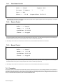
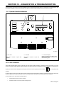
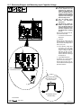
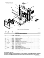
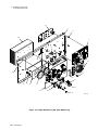
SECTION 5 − INSTALLATION
!Special installation may be
required where gasoline or
volatile liquids are present −
see NEC Article 511 or CEC
Section 20.
1 Lifting Eye
2 Lifting Forks
Use lifting eye or lifting forks to
move unit.
If using lifting forks, extend forks
beyond opposite side of unit.
3 Line Disconnect Device
Locate unit near correct input
power supply.
5-1. Selecting A Location
3
18 in.
(460 mm)
18 in.
(460 mm)
OR
1
2
Movement
Location And Airflow
loc_large 2018-08
!Do not move or operate unit
where it could tip.
276825-A
18 in.
(460 mm)
18 in.
(460 mm)
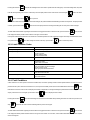
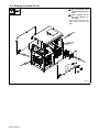
5-2. Dimensions And Weights
Ref. 276825-A
BC
A
*Dimensions
A27-1/2 in. (699 mm)
B21-3/4 in. (552 mm)
C34-3/4 in. (883 mm)
Weight
251 lb (114 Kg)
* Lifting Eye Weight Rating
600 lb (272 kg) Maximum

OM-271150 Page 13
5-3. Electrical Service Guide Elec Serv 2020−02
CE-marked equipment shall only be used on a supply network that is a three-phase, four-wire system with an earthed neutral.
Failure to follow these electrical service guide recommendations could create an electric shock or fire hazard. These
recommendations
are for a dedicated circuit sized for the rated output and duty cycle of the welding power source.
In dedicated circuit installations, the National Electrical Code (NEC) allows the receptacle or conductor rating to be less than the rating
of the circuit protection device. All components of the circuit must be physically compatible. See NEC articles 210.21, 630.11, and
630.12.
50 Hz 3-Phase 60 Hz 3-Phase
Rated Supply Voltage (V) 400 460
Rated Maximum Supply Current I1max (A) 60 50
Maximum Effective Supply Current I1eff (A) 60 50
Maximum Recommended Standard Fuse Rating In Amperes
1
60
70
Time-Delay Fuses
2
70
Normal Operating Fuses
3
90
Maximum Recommended Supply Conductor Length In Feet (Meters)
4
214 (74) 213 (65)
Raceway Installation
Minimum Supply Conductor Size In AWG (mm
2
)
5
6 (16) 8 (10)
Minimum Grounding Conductor Size In AWG (mm
2
)
5
8 (10) 8 (10)
Flexible Cord Installation
Minimum Supply Conductor Size In AWG (mm
2
)
6
4 (25) 4 (25)
Recommended Strain Relief
7
Customer Supplied Customer Supplied
Reference: 2020 National Electrical Code (NEC) (including article 630)
1 If a circuit breaker is used in place of a fuse, choose a circuit breaker with time-current curves comparable to the recommended fuse.
2 “Time-Delay” fuses are UL class “RK5” . See UL 248.
3 “Normal Operating” (general purpose - no intentional delay) fuses are UL class “K5” (up to and including 60 amps), and UL class “H” ( 65 amps and
above).
4 Maximum total length of copper input conductors in entire installation, raceway and/or flexible cord.
5 Raceway conductor data in this section specifies conductor size (excluding flexible cord or cable) between the panelboard and the equipment per
NEC Table 310.15(B)(16) and is based on allowable ampacities of insulated copper conductors having a temperature rating of 75°C (167°F) with not
more than three single current−carrying conductors in a raceway.
6 Flexible cord conductor size is based on NEC Table 400.5(A)(1) for SOOW 600V 90°C (194°F) jacketed cable in a 30°C (86°F) ambient temperature.
See NEC Table 310.15(B)(2)(a) for ambient temperature correction factors. Flexible cord used for connection to the power supply system shall com-
ply with the requirements of CSA C22.2 No. 49.
7 If necessary, have a qualified person enlarge access hole in machine panel to accommodate strain relief.
Notes

OM-271150 Page 14
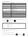
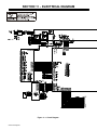
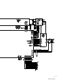
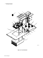
Input3 2015-01 / 276824-A
Tools Needed:
5-4. Connecting 3-Phase Input Power For 400/460 Volt Models
3/8 in.
1
7
10
8
4
9
6
3
GND/PE Earth Ground
2
3
4
56
2
5/32 in.
La page est en cours de chargement...
La page est en cours de chargement...
La page est en cours de chargement...
La page est en cours de chargement...
La page est en cours de chargement...
La page est en cours de chargement...
La page est en cours de chargement...
La page est en cours de chargement...
La page est en cours de chargement...
La page est en cours de chargement...
La page est en cours de chargement...
La page est en cours de chargement...
La page est en cours de chargement...
La page est en cours de chargement...
La page est en cours de chargement...
La page est en cours de chargement...
La page est en cours de chargement...
La page est en cours de chargement...
La page est en cours de chargement...
La page est en cours de chargement...
La page est en cours de chargement...
La page est en cours de chargement...
La page est en cours de chargement...
La page est en cours de chargement...
La page est en cours de chargement...
La page est en cours de chargement...
La page est en cours de chargement...
La page est en cours de chargement...
La page est en cours de chargement...
La page est en cours de chargement...
La page est en cours de chargement...
La page est en cours de chargement...
La page est en cours de chargement...
La page est en cours de chargement...
La page est en cours de chargement...
La page est en cours de chargement...
-
 1
1
-
 2
2
-
 3
3
-
 4
4
-
 5
5
-
 6
6
-
 7
7
-
 8
8
-
 9
9
-
 10
10
-
 11
11
-
 12
12
-
 13
13
-
 14
14
-
 15
15
-
 16
16
-
 17
17
-
 18
18
-
 19
19
-
 20
20
-
 21
21
-
 22
22
-
 23
23
-
 24
24
-
 25
25
-
 26
26
-
 27
27
-
 28
28
-
 29
29
-
 30
30
-
 31
31
-
 32
32
-
 33
33
-
 34
34
-
 35
35
-
 36
36
-
 37
37
-
 38
38
-
 39
39
-
 40
40
-
 41
41
-
 42
42
-
 43
43
-
 44
44
-
 45
45
-
 46
46
-
 47
47
-
 48
48
-
 49
49
-
 50
50
-
 51
51
-
 52
52
-
 53
53
-
 54
54
-
 55
55
-
 56
56


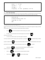
Miller TOCCOTRON AC 907690001 Manuel utilisateur
- Catégorie
- Système de soudage
- Taper
- Manuel utilisateur
dans d''autres langues
Documents connexes
-
Miller TOCCOTRON AC (24 VOLT COOLER) 907690001 Le manuel du propriétaire
-
-
-
-
Miller TOCCOTRON AC 907271011 Le manuel du propriétaire
-
-
-
-
-