MINN KOTA 1358894 Terrova Bow Mount Trolling Motor Le manuel du propriétaire
- Taper
- Le manuel du propriétaire

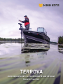
TERROVA
BOW-MOUNT TROLLING MOTOR
Owner's Manual

2 | minnkotamotors.com ©2022 Johnson Outdoors Marine Electronics, Inc.
INTRODUCTION
Made by Minn Kota
Johnson Outdoors
Marine Electronics, Inc.
121 Power Drive
Mankato, MN 56001 USA
Trolling Motors
Produced in XXXX
PRODUCT DESCRIPTION
MODEL XXXXXXX
XXV DC
XX A
SER NO YYDDDC00000
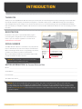
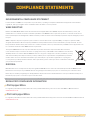
NOTICE: The serial number on your Terrova is located
inside the mount below the motor rests.
EXAMPLE
THANK YOU
Thank you for choosing Minn Kota. We believe that you should spend more time fishing and less time positioning your boat. That’s why
we build the smartest, toughest, most intuitive trolling motors on the water. Every aspect of a Minn Kota trolling motor is thought out
and rethought until it’s good enough to bear our name. Countless hours of research and testing provide you the Minn Kota advantage
that can truly take you “Anywhere. Anytime.” We don’t believe in shortcuts. We are Minn Kota. And we are never done helping you catch
more fish.
REGISTRATION
Remember to keep your receipt and immediately register
your trolling motor. A registration card is included with your
motor or you can complete registration on our website at
minnkotamotors.com/register.
SERIAL NUMBER
Your Minn Kota 11-character serial number is very important. It
helps to determine the specific model and year of manufacture.
When contacting Consumer Service or registering your product,
you will need to know your product’s serial number.
We recommend that you write the serial number down so that
you have it available for future reference.
MOTOR INFORMATION (For Consumer Reference Only)
Model: ___________________________________________________________________________________________________
Serial Number: _____________________________________________________________________________________________
Purchase Date: _____________________________________________________________________________________________
Store Where Purchased: ______________________________________________________________________________________
NOTICE: Do not return your Minn Kota motor to your retailer. Your retailer is not authorized to repair or replace this unit.
You may obtain service by: calling Minn Kota at (800) 227-6433; returning your motor to the Minn Kota Factory Service Center;
sending or taking your motor to any Minn Kota authorized service center. A list of authorized service centers is available on our
website at minnkotamotors.com. Please include proof of purchase, serial number and purchase date for warranty service with any
of the above options.

minnkotamotors.com | 3
©2022 Johnson Outdoors Marine Electronics, Inc.
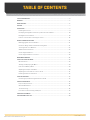
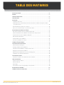
TABLE OF CONTENTS
SAFETY CONSIDERATIONS ......................................................................................................... 4
WARRANTY ............................................................................................................................ 5
KNOW YOUR BOAT .................................................................................................................... 6
FEATURES .............................................................................................................................. 7
INSTALLATION ......................................................................................................................... 8
Installing the Terrova ........................................................................................................ 9
Identifying Trolling Motor Features by Their Associated Cables ....................................... 14
Routing Connection Cables ............................................................................................ 14
Feature overview and connecting the cables .................................................................. 16
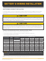
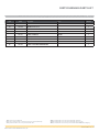
BATTERY & WIRING INSTALLATION ............................................................................................. 21
Boat Rigging & Product Installation ................................................................................ 21
Conductor Gauge and Circuit Breaker Sizing Table ......................................................... 21
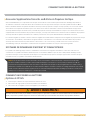
Selecting the Correct Batteries ....................................................................................... 22
Additional Considerations .............................................................................................. 22
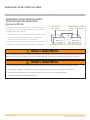
Connecting the Batteries ............................................................................................... 23
Connecting the Batteries in a Series ............................................................................... 24
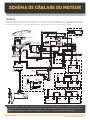
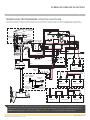
MOTOR WIRING DIAGRAM ........................................................................................................ 26
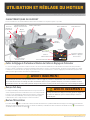
USING & ADJUSTING THE MOTOR .............................................................................................. 28
Mount Features ............................................................................................................. 28
Stowing and Deploying the Motor ................................................................................... 29
Push-to-Test Battery Meter ............................................................................................ 29
Adjusting the Depth of the Motor.................................................................................... 30
Adjusting the Lower Unit for a Secure Stow .................................................................... 31
Installing an External Transducer ................................................................................... 32
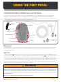
USING THE FOOT PEDAL .......................................................................................................... 33
Controlling Speed & Steering with the Foot Pedal ........................................................... 33
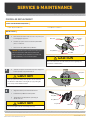
SERVICE & MAINTENANCE ....................................................................................................... 35
Propeller Replacement .................................................................................................. 35
General Maintenance ..................................................................................................... 36
Troubleshooting ............................................................................................................. 36
For Further Troubleshooting and Repair ......................................................................... 37
COMPLIANCE STATEMENTS ...................................................................................................... 38
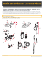
PARTS DIAGRAM & PARTS LIST ................................................................................................. 40

4 | minnkotamotors.com ©2022 Johnson Outdoors Marine Electronics, Inc.
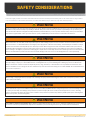
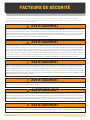
SAFETY CONSIDERATIONS
Please thoroughly read the user manual. Follow all instructions and heed all safety and cautionary notices. Use of this motor is only permitted
for persons that have read and understood these user instructions. Minors may use this motor only under adult supervision.
WARNING
You are responsible for the safe and prudent operation of your vessel. We have designed your Minn Kota product to be an accurate and reliable tool that
will enhance boat operation and improve your ability to catch fish. This product does not relieve you from the responsibility for safe operation of your
boat. You must avoid hazards to navigation and always maintain a permanent watch so you can respond to situations as they develop. You must always
be prepared to regain manual control of your boat. Learn to operate your Minn Kota product in an area free from hazards and obstacles.
WARNING
Never run the motor out of the water, as this may result in injuries from the rotating propeller. The motor should be disconnected from the power source
when it is not in use or is o the water. When connecting the power-supply cables of the motor to the battery, ensure that they are not kinked or subject
to chafe and route them in such a way that persons cannot trip over them. Before using the motor make sure that the insulation of the power cables is
not damaged. Disregarding these safety precautions may result in electric shorts of battery(s) and/or motor. Always disconnect motor from battery(s)
before cleaning or checking the propeller. Avoid submerging the complete motor as water may enter the lower unit through control head and shaft. If the
motor is used while water is present in the lower unit considerable damage to the motor can occur. This damage will not be covered by warranty.
WARNING
Take care that neither you nor other persons approach the turning propeller too closely, neither with body parts nor with objects. The motor is powerful
and may endanger or injure you or others. While the motor is running watch out for persons swimming and for floating objects. Persons who lack the
ability to run the motor or whose reactions are impaired by alcohol, drugs, medication, or other substances are not permitted to use this motor. This
motor is not suitable for use in strong currents. The constant noise pressure level of the motor during use is less than 70dB(A). The overall vibration level
does not exceed 2,5 m/sec2.
WARNING
When stowing or deploying the motor, keep fingers clear of all hinge and pivot points and all moving parts. In the event of unexpected operation, remove
power leads from the battery.
WARNING
It is recommended to only use Johnson Outdoors approved accessories with your Minn Kota motor. Using non-approved accessories including to mount
or control your motor may cause damage, unexpected motor operation and injury. Be sure to use the product and approved accessories, including
remotes, safely and in the manner directed to avoid accidental or unexpected motor operation. Keep all factory installed parts in place including motor
and accessory covers, enclosures and guards.
WARNING
THIS PRODUCT CONTAINS A BUTTON BATTERY. If swallowed, a lithium button battery can cause severe or fatal injuries within two hours. Keep batteries
out of reach of children. If you think batteries may have been swallowed or placed inside any part of the body, seek immediate medical attention.

minnkotamotors.com | 5
©2022 Johnson Outdoors Marine Electronics, Inc.
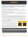
WARRANTY
WARRANTY ON MINN KOTA FRESHWATER TROLLING MOTORS
Minn Kota Freshwater Trolling Motors - Limited Lifetime Warranty On Composite Shaft And Limited
Two-Year Warranty On The Entire Product
Johnson Outdoors Marine Electronics, Inc. (“JOME”) extends the following limited warranty to the original retail purchaser only. Warranty coverage is
not transferable.
Minn Kota Limited Two-Year Warranty on the Entire Product
JOME warrants to the original retail purchaser only that the purchaser’s new Minn Kota freshwater trolling motor will be materially free from defects in
materials and workmanship appearing within two (2) years after the date of purchase. JOME will (at its option) either repair or replace, free of charge,
any parts found by JOME to be defective during the term of this warranty. Such repair, or replacement shall be the sole and exclusive liability of JOME
and the sole and exclusive remedy of the purchaser for breach of this warranty.
Minn Kota Limited Lifetime Warranty on the Composite Shaft
JOME warrants to the original retail purchaser only that the composite shaft of the purchaser’s Minn Kota trolling motor will be materially free from
defects in materials and workmanship appearing within the original purchaser’s lifetime. JOME will provide a new composite shaft, free of charge, to
replace any composite shaft found by JOME to be defective during the term of this warranty. Providing a new composite shaft shall be the sole and
exclusive liability of JOME and the sole and exclusive remedy of the purchaser for breach of this warranty; and purchaser shall be responsible for
installing, or for the cost of labor to install, any new composite shaft provided by JOME.
Exclusions and Limitations
This limited warranty does not apply to products that have been used in saltwater or brackish water, commercially or for rental purposes. This limited
warranty does not cover normal wear and tear, blemishes that do not a ect the operation of the product, or damage caused by accidents, abuse,
alteration, modifi cation, shipping damages, acts of God, negligence of the user or misuse, improper or insu cient care or maintenance. DAMAGE
CAUSED BY THE USE OF OTHER REPLACEMENT PARTS NOT MEETING THE DESIGN SPECIFICATIONS OF THE ORIGINAL PARTS WILL NOT BE
COVERED BY THIS LIMITED WARRANTY. The cost of normal maintenance or replacement parts which are not in breach of the limited warranty are
the responsibility of the purchaser. Prior to using products, the purchaser shall determine the suitability of the products for the intended use and
assumes all related risk and liability. Any assistance JOME provides to or procures for the purchaser outside the terms, limitations or exclusions of this
limited warranty will not constitute a waiver of the terms, limitations or exclusions, nor will such assistance extend or revive the warranty. JOME will not
reimburse the purchaser for any expenses incurred by the purchaser in repairing, correcting or replacing any defective products or parts, except those
incurred with JOME’s prior written permission. JOME’S AGGREGATE LIABILITY WITH RESPECT TO COVERED PRODUCTS IS LIMITED TO AN AMOUNT
EQUAL TO THE PURCHASER’S ORIGINAL PURCHASE PRICE PAID FOR SUCH PRODUCT.
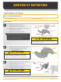
Minn Kota Service Information
To obtain warranty service in the U.S., the product believed to be defective, and proof of original
purchase (including the date of purchase), must be presented to a Minn Kota Authorized Service
Center. Go to www.minnkotamotors.com/support/service-providers/locate to fi nd a Minn Kota
Authorized Service Center. Any charges incurred for service calls, transportation or shipping/
freight to/from the Minn Kota Authorized Service Center, labor to haul out, remove, re-install or
re-rig products removed for warranty service, or any other similar items are the sole and exclusive
responsibility of the purchaser. Products purchased outside of the U.S. must be returned prepaid
with proof of purchase (including the date of purchase and serial number) to any Authorized
Minn Kota Service Center in the country of purchase. To contact Minn Kota Customer Service go
to www.minnkotamotors.com/contact. Products repaired or replaced will be warranted for the
remainder of the original warranty period, or for 90 days from the date of repair or replacement,
whichever is longer. For any product that is returned for warranty service that JOME fi nds to be not
covered by or not in breach of this limited warranty, there will be a billing for services rendered at
the prevailing labor rate of the applicable Minn Kota Authorized Service Center and for a minimum
of at least one hour.
Some states do not allow limitations on how long an implied warranty lasts or the exclusion or limitation of incidental or consequential damages, so the
above limitations and/or exclusions may not apply to you. This warranty gives you specifi c legal rights and you may also have other legal rights which vary
from state to state.
NOTICE: Do not return your Minn Kota product to your retailer. Your retailer is not authorized to repair or replace products.
NOTICE: THERE ARE NO EXPRESS WARRANTIES OTHER THAN THESE LIMITED WARRANTIES. IN NO EVENT SHALL ANY IMPLIED
WARRANTIES INCLUDING ANY IMPLIED WARRANTIES OF MERCHANTABILITY OR FITNESS FOR PARTICULAR PURPOSE, EXTEND BEYOND
THE DURATION OF THE RELEVANT EXPRESS LIMITED WARRANTY. IN NO EVENT SHALL JOME BE LIABLE FOR PUNITIVE, INDIRECT,
INCIDENTAL, CONSEQUENTIAL OR SPECIAL DAMAGES. Without limiting the foregoing, JOME assumes no responsibility for loss of use of product,
loss of time, inconvenience or other damage.
Service Provider
Locator Contact Customer
Service

6 | minnkotamotors.com ©2022 Johnson Outdoors Marine Electronics, Inc.
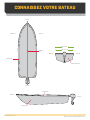
KNOW YOUR BOAT
KeelKeel
BowBow
HullHull
BowBow
SternStern
SternStern
PortPort
PortPort StarboardStarboard
StarboardStarboard
GunwaleGunwale
GunwaleGunwale
TransomTransom
InboardInboard
OutboardOutboard

minnkotamotors.com | 7
©2022 Johnson Outdoors Marine Electronics, Inc.
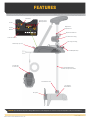
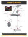
FEATURES
NOTICE: Specifications subject to change without notice. This diagram is for reference only and may dier from your actual motor.
Adjustable Adjustable
Depth CollarDepth Collar
Steering HousingSteering Housing
Cool Quiet Cool Quiet
Power MotorPower Motor
Depth Collar KnobDepth Collar Knob
PropellerPropeller
Stow Deploy Lever Stow Deploy Lever
Low Profile Low Profile
Foot PedalFoot Pedal
Fall Away RampsFall Away Ramps
Lift Assist HousingLift Assist Housing
Indicator PanelIndicator Panel
Push-to-Test Push-to-Test
Battery MeterBattery Meter
AutoPilotAutoPilot
PowerPower
Power Power
ButtonButton
Lift Assist CollarLift Assist Collar
Lifetime Warranty Lifetime Warranty
Flexible Composite ShaftFlexible Composite Shaft

8 | minnkotamotors.com ©2022 Johnson Outdoors Marine Electronics, Inc.
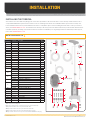
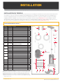
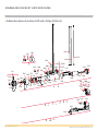
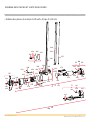
INSTALLATION
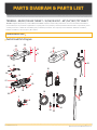
INSTALLING THE TERROVA
Your new Terrova comes with everything you’ll need to directly install it to the boat. This motor can be directly mounted to the boat or
coupled with a Minn Kota quick release bracket for ease of mounting and removal. For installation with a quick release bracket, refer
to the installation instructions provided with the bracket. For compatible quick release mounting brackets and to locate your nearest
dealer, visit minnkotamotors.com. To install the motor directly to the boat, please follow the instructions provided in this manual. Please
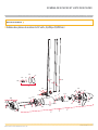
review the parts list, mounting considerations and tools needed for installation prior to getting started. For additional product support,
please visit minnkotamotors.com.
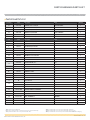
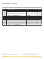
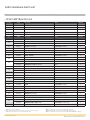
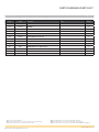
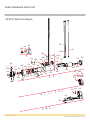
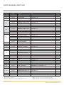
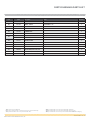
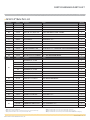
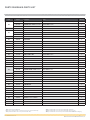
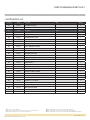
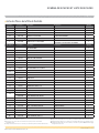
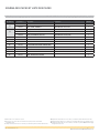
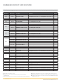
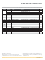
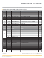
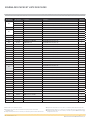
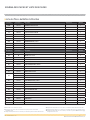
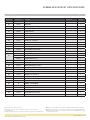
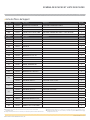
Item /
Assembly Part # Description Qty.
AA 2994864 BAG ASSEMBLY - (BOLT, NUT, WASHERS) 1
1 2263462 BOLT-MOUNTING-1/4X2 W/STG 6
2 2261713 WASHER-1/4 6
3 2263103 NUT NYLOK 1/4-20 MTG 6
4 2301720 WASHER-MOUNTING RUBBER 6
5✖MOTOR ASSEMBLY 1
6 2390800 tÂLANYARD, REMOTE W/ CARABEENER 1
7 2994075 tREMOTE ASY, IPILOT 1
p2397106 tMANUAL, QUICK REF., IPILOT 1.6 1
8 2994076 ÂREMOTE ASSEMBLY LINK TOUCHSCREEN 1
9 2373241 ÂCABLE, USB REMOTE CHARGER LINK 1
10 2375901 ÂADAPTER, USB DC POWER LINK 1
11 2996400 tÂHEADING SENSOR ASSEMBLY *SELECT MODELS ONLY* 1
12 490389-1 ÂCABLE, ETH (M12-M-M12-F, 30' 1
13 2211415 ÌCABLE-EXTENSION, PD/AP 110" *PRE-INSTALLED* 1
490507-1 âCABLE, ADP-INT MDI 14 M12-120" *PRE-INSTALLED* 1
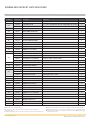
14 2092600 PIN-DRIVE 1.06" LG (SS) 1
2262658 PIN-DRIVE 1" X 3/16" S/S 1
15 2151726 WASHER-5/16 STD (S/S) 1
2091701 WASHER-PROP (LARGE) 1
16 2053101 NUT-PROP,NYLOC (MED) 5/16 SS 1
2093101 NUT-PROP,NYLOC,LG, 3/8 SS 1
17
2091160 PROP-WW2 (3-5/8") REAMED 1
2341160 PROP-WW2 (4.5) W/ADP.RING 1
2331160 PROP-WW2 (4") W/ADP.RING 1
BB 1378131 PROP IND 2091160 WDLS WDG II 1
CC 1378160 PROP KIT 2341160 112# WW2 1
DD 1378132 PROP IND 233160 WDLS WDG II 1
EE 2994722 FT PED ASY, TRV, W/SPOT LCK 1
FF 2994859 BAG, ASY-TERROVA/V2, RUB BUMPERS 1
18 2325110 PAD, FOOT PEDAL 5
p2327132 INSTALLATION INSTRUCTIONS TERROVA 1
p2397107 ÂMANUAL, QUICK REF., IPILOT LINK 3.0 1
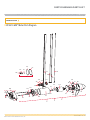
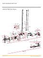
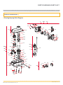
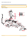
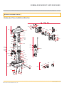
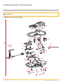
1313
1010
1111
99
1212
22
33
1515 1616 1414
1717
EEEE
55
1818
88
77
44
FFFF
11
66
AAAA
BBBB
CCCC
DDDD
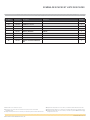
p Not shown on Parts Diagram.
✖ This part is included in an assembly and cannot be ordered individually.
t Only available with models factory installed with i-Pilot.
 Only available with models factory installed with i-Pilot Link.
Ì Only available with models factory installed with Universal Sonar.
â Only available with models factory installed with Built-in MEGA Down Imaging.
INSTALLATION PARTS LIST

minnkotamotors.com | 9
©2022 Johnson Outdoors Marine Electronics, Inc.
INSTALLING THE TERROVA
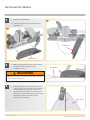
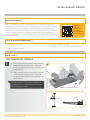
• #3 Phillips Screw Driver
• Drill
• 9/32” Drill Bit
• 7/16” Box End Wrench
• A second person to help with
the installation
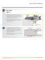
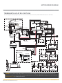
It is recommended that the motor be mounted as close to the centerline of the boat as
possible. Make sure the area under the mounting location is clear to drill holes and install
nuts and washers. Make sure the motor rest is positioned far enough beyond the edge of
the boat. The motor must not encounter any obstructions as it is lowered into the water
or raised into the boat when stowed and deployed. Consider a quick release or adapter
bracket with the installation of your motor. To view a list of accessories, please visit
minnkotamotors.com.
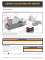
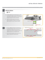
INSTALLING THE TERROVA
a. Place the mount on an elevated, level surface such
as a workbench or the tailgate of a pickup. The
motor, as removed from the box, should be in the
stowed position.
b. Remove the four sideplate screws using a #3 Phillips
screwdriver. Two of these screws will be located on
each side of the mount.
NOTICE: This motor weighs approximately 65lbs.
We recommend having a second person help with
the installation.
DeployedDeployed StowedStowed
Sideplate ScrewSideplate Screw
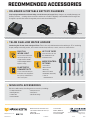
View accessories
available for your
trolling motor at
minnkotamotors.com.
MOUNTING CONSIDERATIONS
TOOLS AND RESOURCES REQUIRED
INSTALLATION
11b

10 | minnkotamotors.com ©2022 Johnson Outdoors Marine Electronics, Inc.
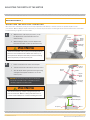
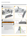
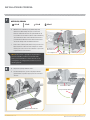
INSTALLING THE TERROVA
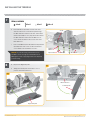
Deck of BoatDeck of Boat
KeelKeel
Right SideplateRight Sideplate
Power CablesPower Cables
Left SideplateLeft Sideplate
Base ExtrusionBase Extrusion
2c
2d
2
WARNING
Make sure the motor is mounted on a level surface and is not
connected to a power source.
4
3
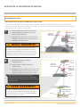
c. Remove the Right Sideplate.
d. Swing the Left Sideplate out and away from the
Base Extrusion.
e. Make sure that the Power Cables from the battery
are disconnected, or that the breaker,
if equipped, is "o."
f. Place the mount as close to the centerline or keel
of the boat as possible. The motor can be installed
on either the Port or Starboard side of the boat
based on personal preference. Check placement
with the motor in the stowed and deployed positions.
Review the mounting considerations at the
beginning of the installation.

minnkotamotors.com | 11
©2022 Johnson Outdoors Marine Electronics, Inc.
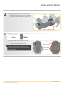
INSTALLING THE TERROVA
ITEM(S) NEEDED
#4 x 6
Drilling LocationsDrilling Locations
Drilling LocationsDrilling Locations
1-1/2" 1-1/2"
MinimumMinimum
GunwaleGunwale
ShaftShaft
Base ExtrusionBase Extrusion
5
6
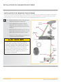
g. When the motor is in the deployed position, make
sure that the Shaft is 1-1/2" out past the Gunwale of
the boat. The lower unit, when stowed and deployed
must not encounter any obstructions.
h. Check to be sure that the mount is level. Use the
Rubber Washers (Item #4) provided to create a level
surface if necessary.
i. It is recommended to mark at least 4 of the 6 holes
in the Base Extrusion and to have a minimum of
two bolts on each side that are located the farthest
apart. Ideal installation would allow for 6 bolts to be
used, with a minimum of 4.
j. Drill through the deck of the boat using a 9/32" Drill
Bit on the marked locations.

12 | minnkotamotors.com ©2022 Johnson Outdoors Marine Electronics, Inc.
INSTALLING THE TERROVA
ITEM(S) NEEDED
#4 x 6#3 x 6
ScrewScrew
Rubber Rubber
WasherWasher
Boat DeckBoat Deck
Nylock NutNylock Nut Flat WasherFlat Washer
Right SideplateRight Sideplate
Left SideplateLeft Sideplate
Base ExtrusionBase Extrusion
NOTICE: To prevent seizing of the stainless steel
hardware, do not use high speed installation tools.
Wetting the screws or applying an anti-seize may help
prevent seizing.
7
8m
88n
#1 x 6
#2 x 6
k. Put a 1/4-20 x 2" (Item #1) screw in each of the
drilled locations. The screw should pass through
the Base Extrusion and the boat deck. If the rubber
washers (Item #4) are used, they should sit between
the Base Extrusion and boat deck. Make sure to
secure the motor with screws on each side of the
Base Extrusion.
l. Place a Flat Washer (Item #2) and then a Nylock Nut
(Item #3) at the end of each screw as shown and
secure. Make sure all hardware is secure.
m. Replace the Right Sideplate.
n. Swing the Left Sideplate back into its correct
position on the Base Extrusion.

minnkotamotors.com | 13
©2022 Johnson Outdoors Marine Electronics, Inc.
INSTALLING THE TERROVA
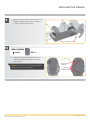
NOTICE: The pads are recommended when using the
Foot Pedal on non-carpeted surfaces.
Foot Pedal Foot Pedal
BottomBottom
Foot Pedal Foot Pedal
Pad PlacementPad Placement
ITEM(S) NEEDED
#18 x 5 #EE x 1
Sideplate ScrewSideplate Screw
9
10
o. Replace the four sideplate screws using a #3 or #2
Phillips screwdriver. Two of these screws will be
located on each side of the mount.
p. Take the Foot Pedal (Item #EE) and turn it over.
Put a Foot Pedal Pad (Item #18) in each of the
pad locations.

14 | minnkotamotors.com ©2022 Johnson Outdoors Marine Electronics, Inc.
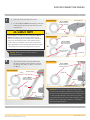
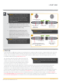
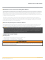
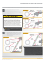
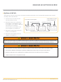
IDENTIFYING TROLLING MOTOR FEATURES BY THEIR ASSOCIATED CABLES
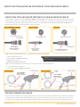
If one connection below the Control Head is present, the motor may be equipped with:
1. i-Pilot and Universal Sonar,
2. i-Pilot and Built-in MEGA Down Imaging,
3. ONLY Universal Sonar, or
4. ONLY Built-in MEGA Down Imaging.
IDENTIFYING TROLLING MOTOR FEATURES BY THEIR ASSOCIATED CABLES
Your trolling motor may be pre-installed with Built-In MEGA Down Imaging OR Universal Sonar, and may include i-Pilot Link. All of these
features require cables to be connected to an output device. These connections are present on the trolling motor and have cables that
exit below the Control Head. To better identify cables present, refer to the diagrams below that detail what the Built-In MEGA Down
Imaging, Universal Sonar and i-Pilot Link cable connectors look like.
Four Pin ConnectorFour Pin Connector
Universal Sonar Universal Sonar
Cable from Cable from
Control HeadControl Head i-Pilot Link Ethernet Cable i-Pilot Link Ethernet Cable
from Control Headfrom Control Head
Locking CollarLocking Collar
Eight Pin ConnectorEight Pin Connector
Fourteen Pin ConnectorFourteen Pin Connector
Built-In MEGA Built-In MEGA
Down Imaging from Down Imaging from
Control HeadControl Head
Built-In MEGA Down Imaging Universal Sonar i-Pilot Link
Control HeadControl Head
Coil CordCoil Cord
i-Pilot i-Pilot
LinkLink
Control HeadControl Head
Coil CordCoil Cord
Built-in MEGA Built-in MEGA
Down Imaging or Down Imaging or
Universal Sonar Universal Sonar
One Connection Two Connections
Built-in MEGA Built-in MEGA
Down Imaging or Down Imaging or
Universal Sonar Universal Sonar
If two connections below the Control Head are present, the motor may be equipped with either:
1. i-Pilot Link and Universal Sonar or
2. i-Pilot Link and Built-in MEGA Down Imaging
ROUTING CONNECTION CABLES
Please follow these instructions for routing any and all of the cables present for any of the pre-installed features that may come with your
trolling motor. This routing should be followed whether there are one or two connection cables present. If you are unsure of the cables
present, please review the “Identifying Trolling Motor Features By Their Associated Cables” section of these Installation Instructions.
Locking CollarLocking Collar
NOTICE: The i-Pilot system does not have an external
wired connection.

minnkotamotors.com | 15
©2022 Johnson Outdoors Marine Electronics, Inc.
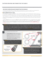
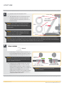
ROUTING CONNECTION CABLES
a. Place the motor in the deployed position.
b. Locate the Built-in MEGA Down Imaging, i-Pilot Link
and/or Universal Sonar cable(s), at the base of the
Control Head.
c. The cable(s) should be fed all the way through
the Coil Cord. It/they should exit the Coil Cord at
the bottom of the Coil Cord, where it connects to
the Mount.
CAUTION
Not following the recommended wire routing for the Built-in
MEGA Down Imaging, i-Pilot Link and/or Universal Sonar
cable(s), if equipped, may cause damage to the product and
void your product warranty. Route cables away from pinch
points or other areas that may cause them to bend in sharp
angles. Routing the cables in any way other than directed may
cause damage to the cables by being pinched or severed.
1
2
Control HeadControl Head
Coil Coil
CordCord
MountMount
i-Pilot i-Pilot
LinkLink
Control Control
HeadHead
Coil CordCoil Cord
MountMount
Built-in MEGA Built-in MEGA
Down Imaging or Down Imaging or
Universal Sonar Universal Sonar
One Connection
Two Connections
Built-in MEGA Built-in MEGA
Down Imaging or Down Imaging or
Universal Sonar Universal Sonar
Control HeadControl Head
Coil CordCoil Cord
i-Pilot Linki-Pilot Link
Control HeadControl Head
Coil CordCoil Cord
Built-in MEGA Built-in MEGA
Down Imaging or Down Imaging or
Universal Sonar Universal Sonar
One Connection
Two Connections
Built-in MEGA Built-in MEGA
Down Imaging or Down Imaging or
Universal Sonar Universal Sonar
Universal Sonar Universal Sonar
Connector Connector
NOTICE: Universal Sonar connector shown for
illustration purposes.
NOTICE: After the cable(s) exit(s) the Coil Cord, it/they
should be routed through an established routing system on
the boat, in an area with minimal interference. Power cables
or other elements that may produce interference for the
sonar signals. Inspect the selected route carefully to ensure
that there are no sharp edges, obstacles, or obstructions
that may damage the cables.

16 | minnkotamotors.com ©2022 Johnson Outdoors Marine Electronics, Inc.
FEATURE OVERVIEW AND CONNECTING THE CABLES
FEATURE OVERVIEW AND CONNECTING THE CABLES
The cable(s) from the Control Head for each feature installed on the trolling motor is connected to an output device separately. Once the
features that may be installed are identified, follow the instructions below to ensure the cables are connected correctly.
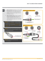
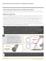
Built-In MEGA Down Imaging
Built-In MEGA Down Imaging delivers nearly 3X the output of standard Side Imaging®, and takes fishfinding into the megahertz frequency for
the very first time. The Minn Kota flagship families of trolling motors, including Ultrex, Ulterra, Terrova, and Fortrex, now include Built-In MEGA
Down Imaging sonar, the clearest imaging available only from Humminbird. With Humminbird MEGA imaging sonar built right into the trolling
motor, you now have a crystal clear view of what’s directly beneath the boat, without having to manage all of the cables that come with external
transducers. The Built-In MEGA DI transducer is only available on new models equipped from the factory and cannot be added to an existing
trolling motor.
The Built-in MEGA DI transducer will provide both MEGA Down Imaging and 2D CHIRP Digital Sonar to select Humminbird models. All Built-In
MEGA DI trolling motors, will come “Apex and Solix Ready” out of the box. An adapter cable accessory (MKR-MDI-1 1852085 or MKR-MDI-2
1852086) is available for purchase that will allow the connection of any compatible Humminbird Helix fish finder. The MKR-MDI-1 is used
on Helix 8, 9, 10, 12 and 15 models. The MKR-MDI-2 is used for Humminbird Helix 7 models only. See the Built-In MEGA Down Imaging
Compatibility chart online.
a. Place the motor in the deployed position.
b. The Built-In MEGA Down Imaging connector from the
Control Head is a 14 pin connector. Built-In MEGA Down
Imaging may be installed on its own, or in conjunction
with an i-Pilot or i-Pilot Link system. It will never be
installed with Universal Sonar. Locate and identify the
correct connection for Built-in MEGA Down Imaging
cable(s), at the base of the Control Head.
1Control HeadControl Head
Coil Coil
CordCord
MountMount
i-Pilot i-Pilot
LinkLink
Built-in MEGA Built-in MEGA
Down Imaging Down Imaging
Fourteen Pin Fourteen Pin
ConnectorConnector
Built-in MEGA Down Built-in MEGA Down
Imaging cable from Imaging cable from
Control HeadControl Head
NOTICE: You can only view Down Imaging with a MEGA DI or MEGA SI HELIX G2N, G3N or G4N Series model and a required adapter, or
with any SOLIX or APEX Series model. The built-in transducer cannot supply MEGA Imaging to Humminbird models that do not already have
the capability. If you have a G2/G2N, G3/G3N HELIX that is not a MEGA SI or MEGA DI model, you will still get 2D Dual Spectrum CHIRP
Sonar from the transducer. SOLIX G1 and HELIX G2 and G2N units need to be running the latest software update to view sonar from motors
with Built-In MEGA Imaging. You can get the latest version of software for your fish finder on humminbird.com. Built-In MEGA Imaging is not
supported by HELIX G1 models or other brands of fish finders.
NOTICE: Built-in MEGA Down Imaging is always paired with
either i-Pilot or i-Pilot Link on Terrova, Ulterra and Ultrex
motors. It may be pre-installed on a Fortrex motor without
other features that require external connections.
NOTICE: Critical cable routing for 60" and 72" motors with
i-Pilot Link and Built-in MEGA Down Imaging. Accessory
Cables must exit the Coil Cord leaving three or more open
coils between where the cables exit and the motor base; as
assembled by the factory. Routing the cables in any other
manner will not allow the motor to stow properly.

minnkotamotors.com | 17
©2022 Johnson Outdoors Marine Electronics, Inc.
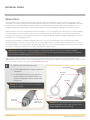
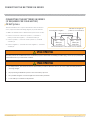
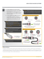
BUILT-IN MEGA DOWN IMAGING
Locking CollarLocking Collar
Fourteen Pin ConnectorFourteen Pin Connector
Built-In MEGA Built-In MEGA
Down Imaging from Down Imaging from
Trolling MotorTrolling Motor
Humminbird Helix Fish Finder
2
Solix/Apex Fish Solix/Apex Fish
Finder ConnectionFinder Connection
Plug directly into Solix/Plug directly into Solix/
Apex Fish FinderApex Fish Finder
Locking CollarLocking Collar
Fourteen Pin ConnectorFourteen Pin Connector
Built-In MEGA Down Imaging Built-In MEGA Down Imaging
from Trolling Motorfrom Trolling Motor
Humminbird Solix or Apex Fish Finder
Keyed Adapter Cable Keyed Adapter Cable
for Helix Fish Finderfor Helix Fish Finder
Adapter Cable Adapter Cable
(Helix ONLY)(Helix ONLY)
Plug into Plug into
Helix Fish Helix Fish
FinderFinder
Adapter Adapter
Cable Keyed Cable Keyed
ConnectionConnection
c. When installing with a Solix or Apex, the Built-In MEGA
Down Imaging cable can be plugged directly into the
Solix/Apex fish finder. Plug the Built-in MEGA Down
Imaging cable into the corresponding connection on
the Solix/Apex fish finder.
d. When installing with a Helix, first attach the Adapter
Cable and then plug the Adapter Cable into the Helix
fish finder. The Adapter Cable will only have one
connection that is keyed on the back of the Helix fish
finder. Plug the Adapter Cable into the only matching
keyed connection.
NOTICE: Check for compatibility or any required adapter
cables online at minnkotamotors.com. The cable from the
trolling motor can be extended with a 10’ Extension Cable
#720081-1 or the 30’ Extension Cable #720081-2 found at
humminbird.com.
NOTICE: If any cables need to be routed, please follow
the guidelines in the Routing Connection Cables section of
these installation instructions.
NOTICE: The connectors are keyed to prevent
reversed installation.

18 | minnkotamotors.com ©2022 Johnson Outdoors Marine Electronics, Inc.
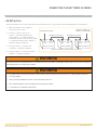
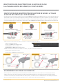
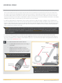
UNIVERSAL SONAR
Four Pin Four Pin
ConnectorConnector Universal Sonar Universal Sonar
Cable from Cable from
Control HeadControl Head
a. Place the motor in the deployed position.
b. Locate the Universal Sonar, if equipped, at the base
of the Mount.
c. Locate the Universal Sonar four pin connector at
the end of Universal Sonar Extension Cable. The
connector is black with a stainless steel threaded
locking collar.
Control HeadControl Head
Coil CordCoil Cord
MountMount
Universal Universal
Sonar Sonar
1
The connector for Universal Sonar exits the trolling motor below the Control Head and consists of a 4-pin plug. An adapter cable
(MKR-US2) that is sold separately is required for all installations. For a current list of compatible fish finders and the correct adapter cable,
or more information on Universal Sonar, please visit minnkotamotors.com.
Universal Sonar
Your trolling motor may be pre-installed with a Universal Sonar transducer system. Universal Sonar is a 2D sonar transducer with a
temperature sensor that is integrated into the lower unit of the trolling motor. It has an operating frequency of 83/200 kHz. Connecting
this transducer to a compatible fish finder gives you a 2D sonar view of what is happening directly below your trolling motor. The
integrated design protects the transducer from underwater hazards, and prevents tangles and damage to the transducer cables.
All Universal Sonar motors are equipped with an internal bonding wire, incorrect rigging will cause sonar interference and can damage
your trolling motor, electronics and other boat accessories. To minimize trolling motor interference, ensure that the fish finder and
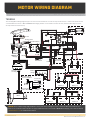
trolling motor are powered by separate batteries. Please refer to the Battery & Wiring Installation and Motor Wiring Diagram sections of
this manual for correct rigging instructions.
The Universal Sonar Cables are shielded to minimize interference. To protect this shielding the cables should not be pulled tight
against sharp angles or hard objects. If using cable ties, do not over-tighten. Any excess cable should be bundled in a loose loop of no
less than 4” in diameter. In certain situations, air bubbles may adhere to the surface of the Universal Sonar transducer, and eect the
performance. If this happens simply wipe the surface of the transducer with your finger.
NOTICE: Universal Sonar does not support imaging screens that require higher frequencies such as 455 kHz or 800 kHz
(Down Imaging, Side Imaging, etc.). Down Imaging (DI) specific units are not compatible with Universal Sonar. See compatibility
chart for a list of compatible fish finders at minnkotamotors.com.
NOTICE: Your fish finder should be turned o until this
procedure is complete.
NOTICE: If the cable length does not reach the desired
fish finder installation location, a 14.5’ extension cable is
available (MKR-US2-11) (sold separately).

minnkotamotors.com | 19
©2022 Johnson Outdoors Marine Electronics, Inc.
Four Pin ConnectorFour Pin Connector
Universal Sonar Universal Sonar
Cable from Cable from
Control HeadControl Head
Universal Sonar Cable from Universal Sonar Cable from
Control Head OR Universal Sonar Control Head OR Universal Sonar
Extension CableExtension Cable
Universal Sonar Universal Sonar
Extension CableExtension Cable
Universal Sonar Universal Sonar
Adapter Cable to Adapter Cable to
fish finderfish finder
Locking CollarLocking Collar
Locking CollarLocking Collar
22d
2e
i-Pilot Link
i-Pilot Link allows your Minn Kota trolling motor and Humminbird to communicate with each other to change the way you fish. i-Pilot Link
delivers a large array of GPS capabilities including controlling speed, steering, Spot-Lock, and the ability to record and retrace paths on
the water, all at your fingertips. To learn more about the GPS capabilities available with your i-Pilot Link navigation system, please refer
to the Owner’s Manual by visiting minnkotamotors.com.
The i-Pilot Link remote and controller make up the i-Pilot Link
navigation system. The i-Pilot Link remote comes paired to the
controller from the factory. The i-Pilot Link controller contains a
very sensitive compass and is where all GPS satellite and i-Pilot
Link remote signals are received. The i-Pilot Link controller is
contained in the trolling motor Control Head and is connected to a fish finder from a connection cable that exits the Control Head.
The Ethernet cable for the i-Pilot Link system has an 8-pin connector. The i-Pilot Link system can be connected directly to the
Humminbird or to the Humminbird Ethernet Switch (optional). If you purchase an Ethernet Switch, install it using the instructions
included in the Ethernet Installation Guide. The Ethernet Extension Cable is optional for your installation. To purchase Ethernet switches,
Ethernet cables, and extension cables, visit the website humminbird.com or call Humminbird Customer Service at 1-800-633-1468.
Depending on the shape of the Ethernet port on your Humminbird fish finder, an additional ethernet adapter cable (Ethernet Adapter
Cable AS EC QDE #720074-1 for Helix fish finders) may be required for the installation. Refer to your fish finder operations manual or see
the i-Pilot Link Compatibility Chart on our website for a list of all compatible Humminbird Units and SC Cards.
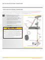
d. Take the Universal Sonar Extension Cable, if needed,
and attach it to the Universal Sonar Cable exiting
the Control Head. Firmly push the plug together and
twist the locking collar until it is snug.
e. Install the Universal Sonar Cable that exits the
Control Head or the Universal Sonar Extension
Cable (if used) to the appropriate Universal Sonar
Adapter Cable. Install the Adapter Cable to your fish
finder. Refer to your fish finder manual for complete
installation instructions.
NOTICE: The Universal Sonar Cable may not be
long enough to reach the fish finder. If the cable
length does not reach the desired fish finder
installation location, a 14.5’ extension cable is
available to purchase. Minn Kota recommends
using the MKR-US2-11.
NOTICE: If any cables need to be routed, please
follow the guidelines in the Routing Connection
Cables section of these installation instructions.
NOTICE: The connectors are keyed to prevent
reversed installation.
NOTICE: The i-Pilot Link system needs an external wired
connection. The i-Pilot system does not need an external
wired connection.
i-PILOT LINK

20 | minnkotamotors.com ©2022 Johnson Outdoors Marine Electronics, Inc.
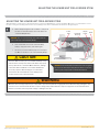
a. Place the motor in the deployed position.
b. The i-Pilot Link connector from the Control Head
is an 8-pin connector. Locate and identify the
correct connection for i-Pilot Link, at the base of
the Control Head.
c. If necessary, to reach the installed fish finder, take
the i-Pilot Link Ethernet Cable (Item #12) and attach
it to the i-Pilot Link cable exiting the Control Head.
d. Install the i-Pilot Link Ethernet Cable directly into
the Humminbird fish finder, or refer to your fish
finder installation manual for complete installation
instructions. If an Adapter Cable is needed (Ethernet
Adapter Cable AS EC QDE for Helix fish finders),
install it on the end of the i-Pilot Link Ethernet Cable
and refer to your fish finder installation manual for
complete installation instructions.
1
2
Control HeadControl Head
Coil Coil
CordCord
MountMount
i-Pilot i-Pilot
LinkLink
Built-in MEGA Built-in MEGA
Down Imaging or Down Imaging or
Universal Sonar Universal Sonar
i-Pilot Link Ethernet i-Pilot Link Ethernet
Cable from Control HeadCable from Control Head
i-Pilot Link Ethernet i-Pilot Link Ethernet
Extension Cable OR Extension Cable OR
Ethernet Extension CableEthernet Extension Cable
Locking CollarLocking Collar
Eight-Pin Eight-Pin
ConnectorConnector
#12 x 1
ITEM(S) NEEDED
NOTICE: i-Pilot Link will be paired with either Built-in
MEGA Down Imaging or Universal Sonar on Ultrex,
Ulterra or Terrova. i-Pilot Link is not a feature oered on
Fortrex motors.
NOTICE: Paired with a Universal Sonar connector for
illustration purposes. A Built-in MEGA Down Imaging
connector may be present instead.
NOTICE: Critical cable routing for 60" and 72" motors with i-Pilot Link and Built-in MEGA Down Imaging. Accessory Cables
must exit the Coil Cord leaving three or more open coils between where the cables exit and the motor base; as assembled by the
factory. Routing the cables in any other manner will not allow the motor to stow properly.
NOTICE: If any cables need to be routed, please follow
the guidelines in the Routing Connection Cables section
of these installation instructions.
NOTICE: The connectors are keyed to prevent
reversed installation.
i-PILOT LINK
La page est en cours de chargement...
La page est en cours de chargement...
La page est en cours de chargement...
La page est en cours de chargement...
La page est en cours de chargement...
La page est en cours de chargement...
La page est en cours de chargement...
La page est en cours de chargement...
La page est en cours de chargement...
La page est en cours de chargement...
La page est en cours de chargement...
La page est en cours de chargement...
La page est en cours de chargement...
La page est en cours de chargement...
La page est en cours de chargement...
La page est en cours de chargement...
La page est en cours de chargement...
La page est en cours de chargement...
La page est en cours de chargement...
La page est en cours de chargement...
La page est en cours de chargement...
La page est en cours de chargement...
La page est en cours de chargement...
La page est en cours de chargement...
La page est en cours de chargement...
La page est en cours de chargement...
La page est en cours de chargement...
La page est en cours de chargement...
La page est en cours de chargement...
La page est en cours de chargement...
La page est en cours de chargement...
La page est en cours de chargement...
La page est en cours de chargement...
La page est en cours de chargement...
La page est en cours de chargement...
La page est en cours de chargement...
La page est en cours de chargement...
La page est en cours de chargement...
La page est en cours de chargement...
La page est en cours de chargement...
La page est en cours de chargement...
La page est en cours de chargement...
La page est en cours de chargement...
La page est en cours de chargement...
La page est en cours de chargement...
La page est en cours de chargement...
La page est en cours de chargement...
La page est en cours de chargement...
La page est en cours de chargement...
La page est en cours de chargement...
La page est en cours de chargement...
La page est en cours de chargement...
La page est en cours de chargement...
La page est en cours de chargement...
La page est en cours de chargement...
La page est en cours de chargement...
La page est en cours de chargement...
La page est en cours de chargement...
La page est en cours de chargement...
La page est en cours de chargement...
La page est en cours de chargement...
La page est en cours de chargement...
La page est en cours de chargement...
La page est en cours de chargement...
La page est en cours de chargement...
La page est en cours de chargement...
La page est en cours de chargement...
La page est en cours de chargement...
La page est en cours de chargement...
La page est en cours de chargement...
La page est en cours de chargement...
La page est en cours de chargement...
La page est en cours de chargement...
La page est en cours de chargement...
La page est en cours de chargement...
La page est en cours de chargement...
La page est en cours de chargement...
La page est en cours de chargement...
La page est en cours de chargement...
La page est en cours de chargement...
La page est en cours de chargement...
La page est en cours de chargement...
La page est en cours de chargement...
La page est en cours de chargement...
La page est en cours de chargement...
La page est en cours de chargement...
La page est en cours de chargement...
La page est en cours de chargement...
La page est en cours de chargement...
La page est en cours de chargement...
La page est en cours de chargement...
La page est en cours de chargement...
La page est en cours de chargement...
La page est en cours de chargement...
La page est en cours de chargement...
La page est en cours de chargement...
La page est en cours de chargement...
La page est en cours de chargement...
La page est en cours de chargement...
La page est en cours de chargement...
La page est en cours de chargement...
La page est en cours de chargement...
La page est en cours de chargement...
La page est en cours de chargement...
-
 1
1
-
 2
2
-
 3
3
-
 4
4
-
 5
5
-
 6
6
-
 7
7
-
 8
8
-
 9
9
-
 10
10
-
 11
11
-
 12
12
-
 13
13
-
 14
14
-
 15
15
-
 16
16
-
 17
17
-
 18
18
-
 19
19
-
 20
20
-
 21
21
-
 22
22
-
 23
23
-
 24
24
-
 25
25
-
 26
26
-
 27
27
-
 28
28
-
 29
29
-
 30
30
-
 31
31
-
 32
32
-
 33
33
-
 34
34
-
 35
35
-
 36
36
-
 37
37
-
 38
38
-
 39
39
-
 40
40
-
 41
41
-
 42
42
-
 43
43
-
 44
44
-
 45
45
-
 46
46
-
 47
47
-
 48
48
-
 49
49
-
 50
50
-
 51
51
-
 52
52
-
 53
53
-
 54
54
-
 55
55
-
 56
56
-
 57
57
-
 58
58
-
 59
59
-
 60
60
-
 61
61
-
 62
62
-
 63
63
-
 64
64
-
 65
65
-
 66
66
-
 67
67
-
 68
68
-
 69
69
-
 70
70
-
 71
71
-
 72
72
-
 73
73
-
 74
74
-
 75
75
-
 76
76
-
 77
77
-
 78
78
-
 79
79
-
 80
80
-
 81
81
-
 82
82
-
 83
83
-
 84
84
-
 85
85
-
 86
86
-
 87
87
-
 88
88
-
 89
89
-
 90
90
-
 91
91
-
 92
92
-
 93
93
-
 94
94
-
 95
95
-
 96
96
-
 97
97
-
 98
98
-
 99
99
-
 100
100
-
 101
101
-
 102
102
-
 103
103
-
 104
104
-
 105
105
-
 106
106
-
 107
107
-
 108
108
-
 109
109
-
 110
110
-
 111
111
-
 112
112
-
 113
113
-
 114
114
-
 115
115
-
 116
116
-
 117
117
-
 118
118
-
 119
119
-
 120
120
-
 121
121
-
 122
122
-
 123
123
-
 124
124


