Solis S6 Mini Single Phase Inverter Manuel utilisateur
- Catégorie
- Adaptateurs secteur
- Taper
- Manuel utilisateur

Installation and Operation Manual
Solis S6 Phase InverterMini Single
S6-GR1P(0.7-3.6)K-M
Ver1.2
Ginlong Technologies Co., Ltd.
Ginlong Technologies Co., Ltd.
No. 57 Jintong Road, Binhai Industrial Park, Xiangshan, Ningbo,
Zhejiang, 315712, P.R.China.
Tel: +86 (0)574 6578 1806
Fax: +86 (0)574 6578 1606
If you encounter any problem on the inverter, please find out the inverter S/N
and contact us, we will try to respond to your question ASAP.
Please adhere to the actual products in case of any discrepancies in this user manual.

2
5
8
8
8
8
8
5
2
3
7
…………………………………………………………………………………………………………………………
…………………………………………………………………………………………………………………………
………………………………………………………………………………………………………………………………
………………………………………………………………………………………………………………………………
……………………………………………………………………………………………………………
……………………………………………………………………………………………………………………………
……………………………………………………………………………………………
………………………………………………………………………………………………………
…………………………………………………………………………………………………………………
…………………………………………………………………………………………………………
……………………………………………………………………………………………………………………………
…………………………………………………………………………………………………………………………
…………………………………………………………………………………………………………………
5
……………………………………………………………………………………………
………………………………………………………………………………………………………………………………
………………………………………………………………………………………………………………………
………………………………………………………………………………………………………………
9
9
11
………………………………………………………………………………………………………………………
……………………………………………………………………………………………………
………………………………………………………………………………………
1. Introduction
2. Safety Instructions
2.1 Safety Symbols
2.2 General Safety Instructions
2.3 Notice For Use
3. Overview
3.1 Front Panel Display
3.2 LED Status Indicator Lights
3.3 Keypad
3.4 LCD
6. Operation
1.1 Product Description
1.2 Packaging
6.2 Information
6.1 Main Menu
4. Installation
4.1 Select Location for the Inverter
4.2 Mounting the Inverter
6.3 Settings
6.4 Advanced Info.
6.5 Advanced Settings
……………………………………………………………………………………………………………………………………
Contents
26
26
26
28
29
32
……………………………………………………………………………………………………………………
…………………………………………………………………………………………………………………
…………………………………………………………………………………………………………………………
7. Maintenance
8. Troubleshooting
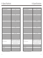
9. Specifications
44
44
47
42
…………………………………………………………………………………………………………………………
6.6 AFCI function
13
……………………………………………………………………………………………………
4.3 Electrical Connections
………………………………………………………………………………………………………………
…………………………………………………………………………………………………………………………
………………………………………………………………………………………………………………
5. Start & Stop
6.1 Start the Inverter
6.2 Stop the Inverter
25
25
25
………………………………………………………………………………………………………………………………
10. Appendix 55
4
…………………………………………………………………………………………………………………………
1.3 Product Storage
7
………………………………………………………………………………………………………………
2.4 Notice for Disposal

1.1 Product Description
.3..2.
Figure 1.1 Front view
Figure 1.2 Bottom view
Inverter x1 Back plate x1
1.2 Packaging
When you receive the inverter, please ensure that all the parts listed below are included:
Fastening screw x2
DC connector x1
(2 pairs for S6-GP1P3.6K-M)
1. Introduction 1. Introduction
If anything is missing, please contact your local Solis distributor.
Solis S6 Mini Single Phase Inverter integrate DRM and backflow power control
function, that could suitable for smart grid requirement.
This manual covers the S6 Mini Single Phase Inverter model listed below:
S6-GR1P0.7K-M, S6-GR1P1K-M, S6-GR1P1.5K-M, S6-GR1P2K-M,
S6-GR1P2.5K-M, S6-GR1P3K-M, S6-GR1P3.6K-M
The following one model is specially supplied for Germany market:
S6-GR1P0.6K-M
AC connector x1 RJ45 connector x1
LCD display
4 buttons
LED lights
DC input
DRM
DC Switch(optional)
CT or Meter input
AC output
RS 485
User manual x1
WiFi/GPRS Stickx1
(Optional)
Manual

1. Introduction 2. Safety Instructions
1.3 Product Storage
Storage temperature must be between -40℃ and 70℃ and the humidity should be
between 0 and 95% non-condensing.
Stacknomorethanfour(4)invertershigh.
If the inverter is not to be installed immediately, storage instructions and environmental
conditions are below:
Use the original box to repackage the inverter, seal with adhesive tape with the
desiccant inside the box.
Store the inverter(s) in a clean and dry place, free of dust and dirt.
Keep box(es) away from corrosive materials to avoid damage to the inverter enclosure.
Inspect packaging regularly. If packaging is damaged(wet, pest damage, etc),
repackage the inverter immediately.
Store the inverter(s) on a flat, hard surface - not inclined or upside down.
After long-term storage, the inverter needs to be fully examined and tested by qualified
service or technical personnel before using.
Restarting after a long period of non-use requires the equipment to be inspected
and, in some cases, the removal of oxidation and dust that has settled inside the
equipment will be required.
2.1 Safety Symbols
Safety symbols used in this manual, which highlight potential safety risks and important
safety information, are listed as follows:
CAUTION:
CAUTION, RISK OF ELECTRIC SHOCK symbol indicates important safety
instructions, which if not correctly followed, could result in electric shock.
CAUTION:
CAUTION, HOT SURFACE symbol indicates safety instructions, which if not
correctly followed, could result in burns.
NOTE:
NOTE symbol indicates important safety instructions, which if not correctly
followed, could result in some damage or the destruction of the inverter.
WARNING:
WARNING symbol indicates important safety instructions, which if not
correctly followed, could result in serious injury or death.
WARNING:
Please don’t connect PV array positive(+) or negative(-) to ground, it could
cause serious damage to the inverter.
WARNING:
Only devices in compliance with SELV (EN 69050) may be connected to the
RS485 and USB interfaces.
2.2 General Safety Instructions
NOTE:
PV module used with inverter must have an IEC 61730 Class A rating.
.5..4.

CAUTION:
Risk of electric shock from energy stored in capacitors of the Inverter.
Do not remove cover for 5 minutes after disconnecting all power sources
(service technician only). Warranty may be voided if the cover is removed
without unauthorized.
CAUTION:
The surface temperature of the inverter can exceed 75℃ (167F).
To avoid risk of burns, DO NOT touch the surface when inverter is operating.
The inverter must be installed out of reach of children.
CAUTION:
The PV array (Solar panels) supplies a DC voltage when they are exposed to
sunlight.
WARNING:
To reduce the risk of fire, over-current protective devices (OCPD) are
required for circuits connected to the Inverter.
The DC OCPD shall be installed per local requirements. All photovoltaic source
and output circuit conductors shall have disconnects that comply with the NEC
Article 690, Part II. All Solis S6 Mini Single Phase Inverters feature an integrated
DC switch.
CAUTION:
Risk of electric shock. Do not remove cover. There is no user serviceable
parts inside. Refer servicing to qualified and accredited service technicians.
WARNING:
Do not touch any inner live parts until 5 minutes after disconnection from
the utility grid and the PV input.
2. Safety Instructions 2. Safety Instructions
2.3 Notice For Use
The inverter has been constructed according to the applicable safety and technical
guidelines. Use the inverter in installations that meet the following specifications only:
Permanent installation is required.
The electrical installation must meet all the applicable regulations and standards.
The inverter must be installed according to the instructions stated in this manual.
The inverter must be installed according to the correct technical specifications.
To startup the inverter, the Grid Supply Main Switch (AC) must be switched on, before
the solar panel's DC isolator shall be switched on. To stop the inverter, the Grid Supply
Main Switch (AC) must be switched off before the solar panel's DC isolator shall be
switched off.
2.4 Notice for Disposal
This product shall not be disposed of with household waste. They should
be segregated and brought to an appropriate collection point to enable
recycling and avoid potential impacts on the environment and human health.
Local rules in waste management shall be respected .
WARNING:
Electrical installations must be done in accordance with the local and national
electrical safety standards.
.6. .7.

Light
1
2
3
POWER
OPERATION
ALARM
3. Overview
3.1 Front Panel Display
3.2 LED Status Indicator Lights
Status
ON
OFF
ON
OFF
OFF
ON
FLASHING
Description
The inverter can detect DC power.
No DC power or low DC power.
The inverter is operating properly.
The inverter has stopped to supply power.
The inverter is initializing.
Alarm or fault condition is detected.
Figure 3.1 Front Panel Display
Table 3.1 Status Indicator Lights
3.3 Keypad
3.4 LCD
There are four keys in the front panel of the Inverter(from left to right):
ESC, UP, DOWN and ENTER keys. The keypad is used for:
Scrolling through the displayed options (the UP and DOWN keys);
Access to modify the adjustable settings (the ESC and ENTER keys).
The two-line Liquid Crystal Display (LCD) is located on the front panel of the Inverter,
which shows the following information:
Inverter operation status and data; Service messages for operator;
Alarm messages and fault indications.
The inverter is operating without fault or alarm.
4. Installation
To select a location for the inverter, the following criteria should be considered:
Do not install in small closed spaces where air cannot circulate freely. To avoid
overheating, always make sure the flow of air around the inverter is not blocked.
Exposure to direct sunlight will increase the operational temperature of the inverter and
may cause output power limiting. Recommends inverter installed to avoid direct sunlight
or raining.
To avoid over heating ambient air temperature must be considered when choosing
the inverter installation location. Recommends using a sun shade minimizing
direct sunlight when the ambient air temperature around the unit exceeds 104°F/40°C.
4.1 Select a Location for the Inverter
Figure 4.1 Recommended Installation locations
WARNING: Risk of fire
Despite careful construction, electrical devices can cause fires.
Do not install the inverter in areas containing highly flammable materials or
gases.
Do not install the inverter in potentially explosive atmospheres.
The mounting structure where the inverter is installed must be fireproof.
.9..8.

Figure 4.3 Inverter wall mounting
Please see Figure 4.4 and Figure 4.5 for instruction on mounting the inverter..
.The inverter shall be mounted vertically. The steps to mount the inverter are listed below
1. According to the figure 4.2, select the mounting height of the bracket and mark the
mounting holes. For brick walls, the position of the holes should be suitable for the
expansion bolts.
2. Make sure the bracket is horizontal. And the mounting holes (in Figure 4.4) are marked
correctly. Drill the holes into wall at your marks.
3. Use the suitable expansion screws to fix the bracket on the wall.
Figure 4.4 Inverter wall mounting
4. Installation4. Installation
Figure 4.2 Inverter Mounting clearance
Install on a wall or strong structure capable of bearing the weight.
Install vertically with a maximum incline of +/- 5°.If the mounted inverter is tilted to an
angle greater than the maximum noted, heat dissipation can be inhibited, and may result
in less than expected output power.
When 1 or more inverters are installed in one location, a minimum 12inchs clearance
should be kept between each inverter or other object. The bottom of the inverter should
be 20inchs clearance to the ground.
300mm
500mm
500mm
300mm 300mm
300mm
300mm
Visibility of the LED status indicator lights and the LCD located at the front panel of
the inverter should be considered.
Adequate ventilation must be provided if the inverter is to be installed in a confined space.
4.2 Mounting the Inverter
Dimensions of mounting bracket:
NOTE:
Nothing should be stored on or placed against the inverter.
Suitable fixing screws
Bracket
.11..10.

+
-
DC 1
DC 2
DC SWITCH
COM
GRID
Figure 4.5 Wall Mount Bracket
WARNING:
The inverter must be mounted vertically.
4.3 Electrical Connections
Inverter designs quick-connect terminal, so top cover needn't open during electrical
connection. The sign meaning located the bottom of inverter, as shown below in table 4.1.
All electrical connections are suit for the local or national standard.
Positive DC input terminal
Negative DC input terminal
Connecting terminal of the Grid
Switch of DC input terminals
RJ45 and terminal block for RS485 communication port
DC input terminal
DC input terminal
Table 4.1 Electrical connection symbols
4. Installation4. Installation
The electrical connection of the inverter must follow the steps listed below:
1. Switch the Grid Supply Main Switch (AC) OFF.
2. Switch the DC Isolator OFF.
3. Assemble PV input connector to the Inverter.
4. Lift up the inverter (be careful to avoid body strain), and align the back bracket on the
inverter with the convex section of the mounting bracket. Hang the inverter on the
mounting bracket and make sure the inverter is secure (see Figure 4.5).
Locking screws
5. Use M4*9 screws in accessory to lock the inverter to the mount bracket.
4.3.1 Connect PV side of inverter
Before connecting inverter, please make sure the PV array open circuit
voltage is within the limit of the inverter.
NOTE:
Before connection, please make sure the polarity of the output voltage of
PV array matches the“DC+”and“DC-”symbols.
WARNING:
Please don’t connect PV array positive or negative pole to the ground,
it could cause serious damages to the inverter.
S6-GR1P0.6K-M, S6-GR1P0.7K-M, S6-GR1P1K-M, S6-GR1P1.5K-M,
S6-GR1P2K-M, S6-GR1P2.5K-M, S6-GR1P3K-M, S6-GR1P3.6K-M
Maximum 600Vdc for
.12. .13.

4. Installation4. Installation
Figure 4.6 DC+ Connector Figure 4.7 DC- Connector
Please use approved DC cable for PV system.
4.0~6.0 4.0(12AWG)
(12~10AWG)
Cable type
Cross section(mm²)
Range
Industry generic PV cable
(model:PV1-F)
Recommended value
The steps to assemble the DC connectors are listed as follows:
1. Strip off the DC wire for about 7mm, Disassemble the connector cap nut. (see Figure 4.8)
3. Crimp the contact pin to the wire using a proper wire crimper. (see Figure 4.10)
2. Insert the wire into the connector cap nut and contact pin. (see Figure 4.9)
4. Insert the contact pin to the top part of the connector and screw up the cap nut to
the top part of the connector .(see figure 4.11).
Figure 4.8
Disassemble the Connector Cap nut
Figure 4.9 Insert the Wire into the
Connector Cap nut and contact pin
5. Then connect the DC connectors to the inverter. Small click will confirm connection.
(see figure 4.12)
Figure 4.10
Crimp the contact pin to the wire
Figure 4.11
Connector with Cap nut Screwed on
Crimping plier
Figure 4.12 Connect the DC Connectors to the Inverter
.14. .15.
CAUTION:
If DC inputs are accidently reversely connected or inverter is faulty or not
working properly, it is NOT allowed to turn off the DC switch. Otherwise it may
cause DC arc and damage the inverter or even lead to a fire disaster.
The correct actions are:
*Use a clip-on ammeter to measure the DC string current.
*If it is above 0.5A, please wait for the solar irradiance reduces until the
current decreases to below 0.5A.
*Only after the current is below 0.5A, you are allowed to turn off the DC
switches and disconnect the PV strings.
* In order to completely eliminate the possibility of failure, please disconnect
the PV strings after turning off the DC switch to aviod secondary failures due
to continuous PV energy on the next day.
Please note that any damages due to wrong operations are not covered in
the device warranty.

4. Installation4. Installation
2.5~6.0 6.0
Cable type
Cross section(mm²)
Range
Industry generic PV cable
Recommended value
Table 4.2 Grid cable size
Figure 4.13 AC Grid Terminal Connector Inside
Each Solis S6 Mini Single Phase Inverter is supplied with an AC grid terminal connector.
Figure 4.14 AC Grid Terminal Connector
The steps to assemble the AC grid terminal connectors are listed as follows:
1. Disassemble the AC connector. Strip the AC wires about 7mm.
Figure 4.15 Stripped AC Wires
Figure 4.16 Connect Wires to the Terminal
Figure 4.17 Tighten up the Cap on the Terminal
4.3.2 Connect grid side of inverter
For all AC connections, 2.5- 6mm 105 ℃ cable is required to be used. Please make sure
2
the resistance of cable is lower than 1 ohm. If the wire is longer than 20m, it's recommended
to use 6mm cable.
2
There are"L","N","PE"symbols marked inside the connector, the Line
wire of grid must be connected to“L”terminal, the Neutral wire of grid must
be connected to "N" terminal and Earth wire must be connected to "PE".
2. Fix the wires into the correct postion. Torque 0.8N.m
Please try to pull out the wire to make sure the it’s well connected.
3. Insert Seal and Clamp Finger into body ,then tighten the nut, torque 2.5+/-0.5N·m.
Code end terminal
Body Seal body Claw Nut
Locker
Housing
.17..16.

4. Installation4. Installation
4.3.3 External ground connection
Figure 4.19 Connect the external grounding conductor
To protect the inverter's AC grid connection conductors, Solis recommends installing
breakers that will protect against overcurrent. The following table defines OCPD ratings for
the Solis S6 Mini Single Phase Inverters.
4.3.4 Max. over current protection device (OCPD)
Table 4.3 Rating of grid OCPD
4.3.5 Inverter monitoring connection
The inverter can be monitored via Wi-Fi or GPRS. All Solis communication devices are
optional (Figure 4.20). For connection instructions, please refer to the Solis Monitoring
Device installation manuals.
Internet
GPRS monitoring
Wi-Fi monitoring
Smart phone monitoring
PC monitoring
Web server
Router
Wi-Fi monitoring
Wi-Fi box
Figure 4.20 Communication function
Figure 4.18 Connect the AC Connector to the Inverter
NOTE: Connection for Split phase grid.
When connect to 208/220/240V split phase, please connect L1 to “L” terminal,
L2 to “N” terminal. Also connect earth to ground terminal.
Inverter
S6-GR1P0.7K-M
Rated output
voltage(V)
Current for protection
device (A)
10
S6-GR1P3K-M
S6-GR1P2.5K-M
S6-GR1P2K-M
S6-GR1P1.5K-M
S6-GR1P1K-M
20
15
15
10
10
220/230
220/230
220/230
220/230
220/230
220/230
Rated output
current (A)
3.2/3.0
4.5/4.3
6.8/6.5
9.1/8.7
13.6/13.0
11.4/10.9
S6-GR1P3.6K-M 20
220/230 16.0
4. Mating plug and socket:
Push the locker onto the socket housing completely, then rotate the locker according to
the direction instructed by the marks on the locker.(Warning:hold the body)
An external ground connection is provided at the right side of inverter.
Prepare OT terminals: M4. Use proper tooling to crimp the lug to the terminal.
Connect the OT terminal with ground cable to the right side of inverter. The torque is 2N.m.
.19..18.
S6-GR1P0.6K-M
(For Germany) 10230 2.6

4. Installation4. Installation
1. The RCD should be in parallel connection between the consumers mains and the solar supply.
2. More than one RCD may be used. Each RCD can protect one or more circuits.
4.3.7 Meter Connection(optional)
The inverter can work with a single phase smart meter to achieve Export Power Management
function and/or 24hour consumption monitoring function.
Below are the connection diagrams of different meters connecting to different locations.
Detailed settings please refer to Section 6.5.12.
Two types of meters are supported:
Direct Insert Type Meter - Max input current 60A (Model:DDSD1352-C)
External CT Type Meter - 120A/40mA CT is supplied (Model: ACR10RD16TE)
Customer can place the order for a suitable meter from Solis Sales Reps.
2-Pin Connector
Pre-made Cable in Meter Package
LNPE
LoadL L' N N'
5 6 7 8
A B
Grid L
Grid N
Grid PE
INV L
INV N
INV PE
Figure 4.22 Direct Insert Type Meter - “Meter in Grid”
INV L
INV N
INV PE
Grid L
Grid N
Grid PE
LNPE
Load
L L' N N'
56 7 8
A B
Pre-made Cable
in Meter Package
2-Pin Connector
Figure 4.23 Direct Insert Type Meter - “Meter in Load”
Isolation switch
Solar supply
main switch
Consumers mains
(to grid)
Main
switch MAIN SWITCHBOARD
Circuits not
protected by
RCDs
Circuits Protected
by RCDs
Isolation device
Inverter with
integral grid
Protection device
Solar
(PV)
array
11
2
Refer to figure 4.21, which is a simple guidance for installing a solar system with PV inverter.
A DC isolator is required to be installed in the system between PV panels with inverter.
Figure 4.21 Guidance for a Simple Installation of an Inverter Solar Energy System
NOTE:
Inverters are classified as "Meter Model" and "CT Model" due to hardware
difference.
Meter Model can only connect a smart meter.
CT Model can only connect a smart sensor.
Please consult Solis Sales Rep before placing the order.
NOTE:
To achieve Export Power Management function, the smart meter can be
installed on either grid side or load side. To achieve 24hour consumption
monitoring function, the smart meter can only be installed on grid side.
.21..20.
4.3.6 Electrical connection diagram

4. Installation 4. Installation
Pre-made Cable in Meter Package RJ45 Connector
2-Pin Connector
Pre-made Cable
in Meter Package
RJ45 Connector
INV L
INV N
INV PE
Grid L
Grid N
Grid PE
CT Arrow Grid
White Black
+ -
LNPE
Load
5 6 7 8 9 10 21 22 23
1 2 3 4 13 12
INV L
INV N
INV PE
Grid L
Grid N
Grid PE
5 6 7 8 9 10 21 22 23
1 2 3 4 13 12
2-Pin Connector
LNPE
Load
CT Arrow Grid
White Black
+ -
Figure 4.24 External CT Type Meter - “Meter in Grid”
Figure 4.25 External CT Type Meter - “Meter in Load”
4.3.8 CT connections(optional)
The inverter can work with a smart sensor to achieve Export Power Management function.
Below is the connection diagram of the smart sensor.
Detailed settings please refer to Section 6.5.12.
Pre-made Cable in CT Package
2-Pin Connector
Grid L
Grid N
Grid PE
INV L
INV N
INV PE
LNPE
Load
CT Arrow Grid
Figure 4.26 Smart Sensor
Inverters are classified as "Meter Model" and "CT Model" due to hardware
difference.
Meter Model can only connect a smart meter.
CT Model can only connect a smart sensor.
Please consult Solis Sales Rep before placing the order.
NOTE:
To achieve Export Power Management function, the smart sensor
must be installed on the grid side.
NOTE:
.23..22.

4. Installation
4.3.9 Logic interface connection
Please follow below steps to assemble RJ45 connector.
1. Insert the network cable into the communication connection terminal of RJ45.
Figure 4.27 RJ45 communication connection terminals
2. Use the network wire stripper to strip the insulation layer of the communication cable.
According to the standard line sequence of figure 4.28 connect the wire to the plug of
RJ45, and then use a network cable crimping tool to make it tight.
Correspondence between the cables
and the stitches of plug, Pin5 and Pin6
of RJ45 terminal is used for the logic
interface, other Pins are reserved.
Pin 1: Reserved; Pin 2: Reserved
Pin 3: Reserved; Pin 4: Reserved
Pin 5: Switch_input1; Pin 6: Switch_input2
Pin 7: Reserved; Pin 8: Reserved
1--8
Rj45 plug
Rj45terminal
1 2 3 4 5 6 7 8
1 2 3 4 5 6 7 8
DRM(logic interface)
Switch_input1 Switch_input2
Figure 4.28 Strip the insulation layer and connect to RJ45 plug
3. Connect RJ45 to DRM (l ) . ogic interface
After wire connection, please refer chapter 6.5.9.1 to enable the logic interface function.
5.1 Start the Inverter
5. Start & Stop
Logic interface is required by some local regulations that can be operated by a simple switch
or contactor(Not available in South Africa).
When the switch is closed the inverter can operated normally. When the switch is opened,
the inverter will reduce it’s output power to zero within 5s.
Pin5 and Pin6 of RJ45 terminal is used for the logic interface connection.
To start up the Inverter, it is important that the following steps are strictly followed:
1. Switch the grid supply main Switch (AC) ON first.
2. Switch the DC switch ON. If the voltage of PV arrays are higher than start up voltage,
the inverter will turn on. The red LED power will light.
3. When both the DC and the AC sides supply to the inverter, it will be ready to generate
power. Initially, the inverter will check both its internal parameters and the parameters
of the AC grid, to ensure that they are within the acceptable limits. At the same time,
the green LED will flash and the LCD displays the information of INITIALIZING.
4. After 30-300 seconds (depending on local requirement), the inverter will start to
generate power. The green LED will be on continually and the LCD displays
GENERATING.
WARNING:
Do not touch the surface when the inverter is operating. It may be
hot and cause burns.
5.2 Stop the Inverter
To stop the inverter, it is mandatory that the steps below are followed in the exact order outlined.
1. Select "Grid Off" in the Advanced Setting of Inverter LCD.
2. Turn off the AC Switch between Solis inverter and Grid.
3. Wait approximately 30 seconds (during this time, the AC side capacitors are dissipating
energy). If the inverter has DC voltage above the start-up threshold, the red POWER
LED will be lit. Switch the DC switch OFF.
4. Confirm all LED's switch OFF (~one (1) minute).
CAUTION
Although the inverter DC disconnect switch is in the OFF position and all
the LED's are OFF, operators must wait five (5) minutes after the DC power
source has been disconnected before opening the inverter cabinet. DC
side capacitors can take up to five (5) minutes to dissipate all stored energy.
.25..24.

During normal operation, the display alternately shows the power and the operation
status with each screen lasting for 10 seconds (see Figure 6.1). Screens can also be
scrolled manually by pressing the UP and DOWN keys. Press the ENTER key to
access to the Main Menu.
5 sec
Start
Power 3424W
01-01-2020 00:00
Status: Generating
01-01-2020 00:00
Information
Settings
Advanced Info.
Advanced settings
UP/DOWN
UP/DOWN
UP/DOWN
UP/DOWN or
auto-scroll
(10 sec)
Pressing the
ENTER key
gives access to
the main menu.
Pressing the
ESC key
calls back the
previous menu.
Main Menu
Figure 6.1 Operation Overview
6.1 Main Menu
There are four submenus in the Main Menu (see Figure 6.1):
1. Information
2. Settings
3. Advanced Info.
4. Advanced Settings
The Solis S6 Mini Single Phase Inverter main menu provides access to operational data and
information. The information is displayed by selecting "Information" from the menu
and then by scrolling up or down.
6.2 Information
6. Operation6. Operation
V_DC1 350.8V
I_DC1 5.1A
V_Grid 230.4V
I_Grid 8.1A
Status: Generating
Power: 1488W
Grid Frequency
F_Grid 60.06Hz
Total Energy
0258458 kwh
This Month: 0123kwh
Last Month: 0123kwh
Today: 15.1kwh
Yesterday: 13.5kwh
10 sec
10 sec
10 sec
10 sec
10 sec
10 sec
10 sec
V_DC1: Shows input 01 voltage value.
I_DC1: Shows input 01 current value.
V_Grid: Shows the grid's voltage value
I_Grid: Shows the grid's current value.
Status: Shows instant status of the Inverter.
Power: Shows instant output power value.
F_Grid: Shows the grid's frequency value.
Total generated energy value.
This Month: Total energy generated this month.
Last Month: Total energy generated last month.
Today: Total energy generated today.
Yesterday: Total energy generated yesterday.
Display Duration Description
Inverter SN
00000000000000 10 sec
10 sec
Display series number of the inverter.
Power of ERM.
Current of EPM.
V_DC2 350.8V
I_DC2 5.1A 10 sec V_DC2: Shows input 02 voltage value.
I_DC2: Shows input 02 current value.
10 sec Work Mode:The work mode of inverter.
DRM Number:Show the number 01-08.
Work Mode: NULL
DRM Number: 08
10 sec Meter EnergyP:The active power.
Meter EnergyP
0000000.00kWh
Export_P: +0000W
Export_I: 00.0A
Table 6.1 Information list
.27..26.

6. Operation6. Operation
5.2 Stop the Inverter
6.2.1 Lock screen
Pressing the ESC key returns to the Main Menu. Pressing the ENTER key locks
(Figure 6.2(a)) or unlocks (Figure 6.2 (b)) the screen.
(b)(a)
Figure 6.2 Locks and Unlocks the Screen of LCD
The following submenus are displayed when the Settings menu is selected:
1. Set Time
2. Set Address
6.3 Settings
6.3.1 Set Time
This function allows time and date setting. When this function is selected, the LCD will
display a screen as shown in Figure 6.3.
NEXT=<ENT> OK=<ESC>
01-01-2020 00:00
Figure 6.3 Set Time
Press the UP/DOWN keys to set time and data. Press the ENTER key to move from one
digit to the next (from left to right). Press the ESC key to save the settings and return to
the previous menu.
6.3.2 Set Address
This function is used to set the address when muti inverters are connected to single monitor.
The address number can be assigned from “01”to “99”.
The default address number of Solis S6 Mini Single Phase Inverter is “01”.
YES=<ENT> NO=<ESC>
Set Address: 01
Figure 6.4 Set Address
Press the UP/DOWN keys to set the address. Press the ENTER key to save the settings.
Press the ESC key to cancel the change and return to the previous menu.
6.4 Advanced Info - Technicians Only
NOTE:
To access to this area is for fully qualified and accredited technicians only.
Enter menu “Advanced Info.” and “Advanced settings” (need password).
Select “Advanced Info.” from the Main Menu. The screen will require the password as below:
YES=<ENT> NO=<ESC>
Password:0000
Figure 6.5 Enter password
The default password is “0010".
Please press “down” to move the cursor, press “up” to select the number.
After enter the correct password the Main Menu will display a screen and be able to access
to the following information.
1. Alarm Message
2. Running message
3.Version
4. Daily Energy
5. Monthly Energy
6. Yearly Energy
7. Daily Record
8. Communication Data
9. Warning Message
6.4.1 Alarm Message
The display shows the latest alarm messages. Screens can be scrolled manually by 100
pressing the UP/ DOWN keys. Press the ESC key to return to the previous menu.
Alarm001: OV-G-V
Time: 00-00 Data: 7171
Figure 6.6 Alarm Message
6.4.2 Running Message
This function is for maintaince person to get running message such as internal temperature,
Standard No.etc.
Screens can be scrolled manually by pressing the UP/DOWN keys.
.29..28.

6. Operation6. Operation
6.4.4 Daily Energy
The function is for checking the energy generation for selected day.
Figure 6.8 Select date for daily energy
YES=<ENT> NO=<ESC>
Select: 2020-01-01
Press DOWN key to move the cursor to day, month and year, press UP key to change the digit.
Press Enter after the date is fixed.
2020-01-01: 051.3kWh
2020-01-01: 061.5kWh
Figure 6.9 Daily energy
Press UP/DOWN key to move one date from another.
6.4.8 Communication Data
The screen shows the internal data of the Inverter (see Figure 6.14), which is for service
technicians only.
01-05: 01 25 E4 9D AA
06-10: C2 B5 E4 9D 55
Figure 6.14 Communication Data
6.4.6 Yearly Energy
YES=<ENT> NO=<ESC>
Select: 2020
Figure 6.12 Select year for yearly energy
2020: 0017513kWh
2019: 0165879kWh
Figure 6.13 Yearly energy
Press UP/DOWN key to move one date from another.
The function is for checking the energy generation for selected year.
Press DOWN key to move the cursor to day and year, press UP key to change the digit.
Press Enter after the date is fixed.
6.4.7 Daily record
The screen shows history of changing settings. Only for maintance personel.
6.4.3 Version
The screen shows the model version and the software version of the Inverter
Model: 08
Software Version: D20001
Figure 6.7 Model Version and Software Version
6.4.5 Monthly Energy
YES=<ENT> NO=<ESC>
Select: 2020-01
Figure 6.10 Select month for monthly energy
The function is for checking the energy generation for selected month.
Press DOWN key to move the cursor to day and month, press UP key to change the digit.
Press Enter after the date is fixed.
2020-02: 0510kWh
2020-01: 0610kWh
Figure 6.11 Month energy
Press UP/DOWN key to move one date from another.
The display shows the latest warn messages (see Figure 6.15). Screens can be scrolled 100
manually by pressing the UP/ DOWN keys. Press the ESC key to return to the previous menu.
Msg000:
T: 00-00 00:00 D:0000
Figure 6.15 Warning Message
6.4.9 Warning Message
.31..30.

6. Operation6. Operation
6.5 Advanced Settings - Technicians Only
NOTE:
To access to this area is for fully qualified and accredited technicians only.
Please follow 6.4 to enter password to access this menu.
Select Advanced Settings from the Main Menu to access the following options:
1. Select Standard
2. Grid ON/OFF
3. 24H Switch
4. Clear Energy
5. Reset Password
6. Power Control
7. Calibrate Energy
8. Special Settings
9. STD. Mode Settings
10. Restore Settings
11. HMI Update
12. Internal EPM Set
13. External EPM Set
14. Restart HMI
15. Debug Parameter
16. DSP Update
17. Power Parameter
6.5.1 Selecting Standard
This function is used to select the grid's reference standard (see Figure 6.16).
YES=<ENT> NO=<ESC>
Standard:AS4777-02
Figure 6.16
Press the UP/DOWN keys to select the standard (AS4777-02,AS4777-15, VDE4105, VDE0126,
UL-240V-A, UL-208V-A, UL-240V, UL-208V, MEX-CFE, G83/2 (for 1-3.6kW models), G59/3
(for 4-5kW models), C10/11, EN50438 DK, EN50438 IE, EN50438 NL and “User-Def” function).
Selecting the “User-Def” menu will access to the following submenu (see Figure 6.17),
Figure 6.17
OV-G-V1: 260V
OV-G-V1-T: 1S
NOTE:
The " User-Def" function can be only used by the service engineer and
must be allowed by the local energy supplier.
Below is the setting range for “User-Def”.
Using this function, the limits can be changed manually.
This function is used to start up or stop the power generation of Solis Single Phase Inverter.
Grid ON
Grid OFF
Figure 6.18 Set Grid ON/OFF
Screens can be scrolled manually by pressing the UP/DOWN keys. Press the ENTER key
to save the setting. Press the ESC key to return to the previous menu.
6.5.2 Grid ON/OFF
NOTE:
This function is for technicians use only.
NOTE:
For different countries, the grid standard needs to be set as different
according to local requirements. If there is any doubt, please consult
Solis service technicians for details.
.33..32.
Table 6.2 Setting ranges for User-Def (L-N)
OV-G-V1: 176---290V
OV-G-V1-T: 0.01---600S
OV-G-V2: 176---290V
OV-G-V2-T: 0.01---600S
UN-G-V1: 110---220V
UN-G-V1-T: 0.01---600S
UN-G-V2: 110---220V
UN-G-V2-T: 0.01---600S
Startup-T: 10-600S
OV-G-F1: 50.1-65Hz
OV-G-F1-T: 0.01---600S
OV-G-F2: 50.1-65Hz
OV-G-F2-T: 0.01---600S
UN-G-F1: 45-59.9Hz
UN-G-F1-T: 0.01---600S
UN-G-F2: 45-59.9Hz
UN-G-F2-T: 0.01---600S
Restore-T: 10-600S

6. Operation6. Operation
6.5.3 24H Switch
This function controls the 24H hours consumption function enable or disable.
Enable
Disable
Figure 6.19 Set 24H ON/OFF
NOTE:
When this is enabled, the inverter LCD will still be alive at night with
the power LED light on. If the grid is in malfunction at night, the system can’t
recover even after the grid is back to normal but the consumption data will
still be recorded in the meter. Until the sunrise, the system will start to work
again while the meter data can be uploaded to the Solis monitoring system
to calibrate the load consumption data.
These two functions are applicable by maintenance personnel only, wrong
operation will prevent the inverter from working properly.
6.5.4 Clear Energy
Clear Energy can reset the history yield of inverter.
6.5.5 Reset Password
This function is used to set the new password for menu “Advanced info.” and “Advanced
information” (see Figure 6.20).
Figure 6.20 Set new password
YES=<ENT> NO=<ESC>
Password: 0000
Enter the right password before set new password. Press the DOWN key to move the cursor,
Press the UP key to revise the value. Press the ENTER key to execute the setting.
Press the ESC key to return to the previous menu.
6.5.7 Calibrate Energy
Maintenance or replacement could clear or cause a different value of total energy. Use this
function could allow user to revise the value of total energy to the same value as before. If
the monitoring website is used the data will be synchronous with this setting automatically.
Figure 6.21 Calibrate energy
YES=<ENT> NO=<ESC>
Energy:0000000kWh
Press the DOWN key to move the cursor, Press the UP key to revise the value. Press the
ENTER key to execute the setting. Press the ESC key to return to the previous menu.
6.5.8 Special Settings
This function is applicable by maintenance personnel only, wrong operation
will prevent the inverter from working properly.
6.5.6 Power control
Active and reactive power can be set through power setting button.
There are 5 item for this sub menu:
1. Set output power
2. Set Reactive Power
3. Out_P With Restore
4. Rea_P With Restore
5. Select PF Curve
This function is applicable by maintenance personnel only, wrong operation
will prevent the inverter from reaching maximum power.
.35..34.

6. Operation6. Operation
6.5.10 Restore Settings
Please follow below settings to enable the DRM. DRM default setting is “OFF” , if DRM set “ON”,
but the logic interface un-connected to the switch or the switch is open, the inverter HMI will
display “Limit by DRM” and the inverter output power will be limited to zero.
1. Select Initial Settings
2. Select DRM and set it “ON”
Restore setting could set all item in 6.5.8 special setting to default.
Thescreenshowsasbelow:
Figure 6.22 Restore Settings
Are you sure?
YES=<ENT> NO=<ESC>
PresstheEnterkeytosavethesettingaftersettinggridoff.
PresstheESCkeytoreturnthepreviousmean.
6.5.11 HMI Update
This function is used for updating the LCD program.
6.5.12 Internal EPM Set
This section includes two functions related to the smart meter or smart sensor.
Please refer to section 4.3.7 or 4.3.8 for detailed connection diagrams.
Function 1: Internal Export Power Management Function
Inverters can work with a smart meter OR a smart sensor to dynamically limit
the export power of the system. Zero injection can be achieved.
Smart meter can be installed either on the grid side OR the load side.
Smart sensor can only be installed on the grid side.
Function 2: 24 Hour Consumption Monitoring Function
Only applicable if Solis monitoring system is used.
Inverters can work with a smart meter to monitor the load consumption data
for the whole day and the data will be displayed on the Solis monitoring system.
Smart meter can only be installed on the grid side.
Please refer to below instructions for different user scenarios.
Scenario 1. Only Function 1 is required
Using a Smart Meter:
Step 1: Refer to Section 4.3.7 to connect the smart meter on the grid side or
load side.
Step 2: Select the corresponding meter model in Section 6.5.12.4
Step 3: Select the Section 6.5.12.1 Mode Select as Option 2(Meter in Load)
or Option 3 (Meter in Grid) accordingly.
Step 4: Configure the Section 6.5.12.2 to set the allowed backflow power.
Step 5: Configure the Section 6.5.12.3 to enable the failsafe function
(If necessary).
Using a Smart Sensor:
Step 1: Refer to Section 4.3.8 to connect the smart sensor on the grid side.
Step 2: Select the Section 6.5.12.1 Mode Select as Option 5(Current Sensor).
Step 3: Configure the "CT Sampling Ratio" and "CT Link Test" if necessary.
Step 4: Configure the Section 6.5.12.2 to set the allowed backflow power.
Step 5: Configure the Section 6.5.12.3 to enable the failsafe function
(If necessary).
6.5.9 STD Mode settings
There are 5 setting under STD. Mode settings.
1. Working mode
2. Power Rate limit
3. Freq. Derate set
4. 10mins OV-G-V set.
5. Initial Settings
This function is applicable by maintenance personnel only, wrong operation
will prevent the inverter from reaching maximum power.
This function is applicable by maintenance personnel only, wrong operation
will prevent the inverter from reaching maximum power.
NOTE:
NOTE:
.37..36.
La page est en cours de chargement...
La page est en cours de chargement...
La page est en cours de chargement...
La page est en cours de chargement...
La page est en cours de chargement...
La page est en cours de chargement...
La page est en cours de chargement...
La page est en cours de chargement...
La page est en cours de chargement...
La page est en cours de chargement...
-
 1
1
-
 2
2
-
 3
3
-
 4
4
-
 5
5
-
 6
6
-
 7
7
-
 8
8
-
 9
9
-
 10
10
-
 11
11
-
 12
12
-
 13
13
-
 14
14
-
 15
15
-
 16
16
-
 17
17
-
 18
18
-
 19
19
-
 20
20
-
 21
21
-
 22
22
-
 23
23
-
 24
24
-
 25
25
-
 26
26
-
 27
27
-
 28
28
-
 29
29
-
 30
30


Solis S6 Mini Single Phase Inverter Manuel utilisateur
- Catégorie
- Adaptateurs secteur
- Taper
- Manuel utilisateur