Ideal 61-955 SureTrace Circuit Tracers Manuel utilisateur
- Catégorie
- Testeurs de réseau câblé
- Taper
- Manuel utilisateur

#61-955
#61-957
#61-959
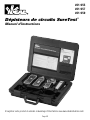
SureTrace™ Circuit Tracers
Instruction Manual
Register your product and access more information at www.idealindustries.com

Page 2
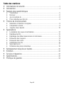
Table of Contents
• SafetyInformation ..................................................................................3
• Introduction ............................................................................................4
• CalloutsofFeatures
• Transmitter ............................................................................................................5
• Receiver ................................................................................................................6
• TestLeadKit ........................................................................................................ 8
• InductiveClampwithBatteryPack ........................................................................ 9
• TheoryofOperation
• SignalGenerationandDetection ..........................................................................9
• OpenversusClosedCircuits ................................................................................9
• RemoteReturnPath ............................................................................................10
• Applications
• Pre-testOperation ............................................................................................... 11
• LocatingCircuitBreakers/Fuses .........................................................................12
• TracingWires .....................................................................................................13
• TracingLowVoltageandDataCables ................................................................13
• FindingOpens ....................................................................................................14
• FindingShorts ....................................................................................................15
• SortingBundledWires ........................................................................................16
• TracingUnderground .......................................................................................... 17
• InductiveClampUses ......................................................................................... 18
• BatteryReplacement ............................................................................. 20
• FuseReplacement ................................................................................ 21
• Maintenance ......................................................................................... 22
• ServiceandReplacementParts ............................................................ 22
• Specifications ...................................................................................... 22
• WarrantyStatement .............................................................................. 24

Page 3
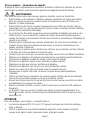
Read first: Safety Information
Understandandfollowoperatinginstructionscarefully.Usethetraceronlyasspecifiedin
thismanual;otherwise,theprotectionprovidedbythetracermaybeimpaired.
WARNING
Toavoidelectricshock,personalinjury,ordeath,followtheseinstructions:
• Beforeusingorconnectingthetracer,visuallyinspecttoensurethecasesarenot
crackedandbackcaseissecurelyinplace.Donotuseiftracerappearsdamaged.
• Beforeusingthetestleads,inspectcarefullyfordamagedinsulation,exposedmetalor
crackedprobes.Donotuseleadsiftheyappeardamaged.
• Thisproductisonlytobeusedbypersonstrainedandexperiencedinworkingwithhigh
voltages,andwhoareawareofthedangersandprecautionstobetakenwhenworking
insuchenvironments.Observelockoutandtagoutprotocolswhereappropriate.
• Neverusethetracerwitharemotegroundinpatientcareareas.Groundcurrents
generatedbythetracermaycreateashockhazardforelectricallysusceptiblepatients.
• Alwaystesttheremotegroundsystemtoconfirmthatitsresistanceislessthan100
ohmsfromremotegroundtocircuitneutral.
• Alwayscheckcircuitstoverifythatthehot,neutralandgroundarewiredcorrectly.
• Donotusetracerifitoperatesabnormallyasprotectionmaybeimpaired.
• Donotuseduringelectricalstormsorinwetweather.
• Donotusearoundexplosivegas,dust,orvapor.
• Donotapplymorethantheratedvoltagetothetracer.
• Donotusewithoutthebatteriesandthebackcaseproperlyinstalled.
• Removethetestleadsfromthecircuitpriortoremovingthebatterycover.
• Donotattempttorepairthisunitasithasnouser-serviceableparts.
• Useonlyapprovedconnectingleads.Donotuseimprovisedconnectionsthatcould
presentasafetyhazard.
• Alwaysensurethattestleadsaresecuredsothattheycannotbeaccidentallysnagged
ortrippedover.
• Whenswitchingonthetransmitter,alwaysverifythatthethreeindicatorLEDs
illuminatebrieflyonpowerup.
• TheLineEnergizedfeatureprovidesanadditionalsafetyalert.Iftheindicatorisnot
illuminated,alwaysindependentlyconfirmthestatusofthelinetobeabsolutelysure.
CAUTION
Toprotectyourself,think“SafetyFirst”:
• Voltagesexceeding30VACor60VDCposeashockhazardsousecaution.
• Useappropriatepersonalprotectiveequipmentsuchassafetyglasses,faceshields,
insulatinggloves,insulatingboots,and/orinsulatingmats.
• Nevergroundyourselfwhenworkingonanelectricalcircuit.
• Alwaysmakethegroundorneutralconnectionfirst,andremovelastwhenusingclip
leads or adaptor cord.

Page 4
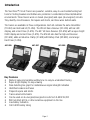
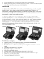
Introduction
TheSureTrace™CircuitTracersarepowerful,versatile,easy-to-usetroubleshootingtest
toolsforfindingbreakersandhiddenwireproblemsinresidential/commercial/industrial
environments.Thesetracersworkonclosed(energized)andopen(de-energized)circuits.
Theyidentifycircuitbreakers,findopensandshorts,andtracewiresbehindwalls.
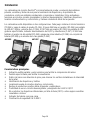
Thetracersareavailableinthreeconfigurations.Eachkitcontainsthesametransmitter
(TR-955)andtestleadkit(TL-956).The955kithasaReceiver(RC-955)withanLED
display,andaHardCase(C-955).The957kithasaReceiver(RC-959)withasuper-bright
OLEDdisplayandaHardCase(C-955).The959kitalsohasthehigh-endReceiver
(RC-959),addsanInductiveClamp(IC-958)withBatteryPack(BP-958),andalarger
HardCase(C-959).
Key Features
• Numericvalueandvariableaudibletoneforeasy-to-understandtracing
• Super-brightdisplayforeasy-viewing
• Peakdetectingbargraphforinstantaneoussignalstrengthindication
• Identifiesbreakersandfuses
• Pinpointsopensandshorts
• Traceswiresbehindwalls
• Canbeusedonde-energized/energizedcircuitsfrom0-600VAC/DC
• WillnotaffectGFCIsorothersensitiveequipmentontheline
• Lowbatteryindication
• CatIII-600Vsafetyrating
#61-955 #61-957 #61-959

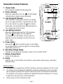
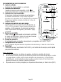
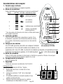
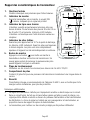
Transmitter Callout Features
1. Output Jacks
Non-polarized,standardbananaplugtype.
2. Power Indicator
WhenthetransmitterisOn,theLEDilluminates
indicatingthatasignalisbeingproduced.
3. Line Energized Indicator
Thetransmittercontinuouslymonitorsthevoltage
acrossitsoutputterminals.Ifgreaterthan30volts
ACor40voltsDCispresent,theLEDindicator
illuminates.Thetransmitteralsocommunicatesthe
linevoltagestatetothereceiver.
4. Low Battery Indicator
Whenthebatteriesapproachthe10%discharge
point,theLEDlights.Oncethebatteries
aredepleted,theLEDflashes.Atthispoint,the
batteriesarefullyexhausted,andtheunitforces
power down.
5. Power Button
Depressthebuttontoswitchpoweronandenable
thetransmitfunction.Depressagaintoconservebattery
powerwhennotinuse.
6. Operating Voltage Range
Operatesonenergized/de-energizedcircuitsfrom0to600VAC/DC.
7. Battery Compartment
Holds(4)AAbatteries.
8. Safety
RatedforuseinCatIII-600Venvironments.Incorporatesahigh-energy,fast-acting
protection fuse.
AdditionalNotes
• Thetransmitter’ssignaldoesnotaffectsensitive,electronicequipmentonthecircuit.
• Inaclosedcircuit,becausethetransmittergeneratesasmalltestcurrent,itssignal
canbedetectedupstreamthroughthefeederpanelandthedistributiontransformer.
Thestrengthofthesignalisreducedasitpassesthroughthetransformerininverse
proportiontotheturnsratioofthetransformer.
• CanbeusedonGFCIprotectedcircuits.
TR-959
1
5
6
8
7
2
3
4
Page 5

Page 6
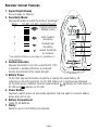
RC-955
1
4
5
3
2
6
7
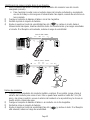
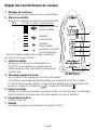
Receiver Callout Features
1. Super Bright Display
Seenextpageforfeatures.
2. Sensitivity Mode:
Depressthisbuttontoselectthemodeofsensitivity*:
Mode RC-955 RC-959 AntennaStrength
4 highestsensitivity
(defaultmode)
3 high-medium
sensitivity
2 medium-low
sensitivity
1 lowestsensitivity
forbreakers
* See Additional Notes on next page for guidelines on
mode selection.
3. Audible Indication
DepressthisbuttontoturnthesoundOn/Off.IfOn
isselected,avariablepitch/toneisproduced-
directlyproportionaltothesignalstrength.
4. Battery Power
OnRC-955,depressthisbuttonatanytimetodisplaytheusefulbatterylife
remainingontheLEDsegments.OnRC-959,batterylifeiscontinuouslydisplayed
onthemainscreen.Batteriesmustbereplacedwhendisplaysonmainscreenof
RC-955andappearsonRC-959.
5. Power Button
Depresstoswitchpoweronandenableoperation.Depressagaintoconservebattery
powerwhennotinuse.
6. Battery Compartment
Holds(3)AAbatteries.
7. Safety
RatedforuseinCatIII-600Venvironments.

Page 7
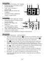
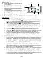
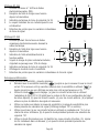
RC-955Display
1. Bright,2-digitLEDdisplay.(180°Rotating)
2. Displaysthepoweredlinestatusreceived
fromthetransmitter.
3. “0-99”numericindicationof
signalstrength.
4. Indicatorlightswhenaudibletone
isdisabled.
5. Peakdetectorshowsinstantaneous
changesinsignalstrength.
RC-959Display
1. Super-brightOLEDdisplay(90°rotating).
2. Displaysthepoweredlinestatusreceived
fromthetransmitter.
3. IndicatesOn/Offstatusofthe
audibletone.
4. LowBatteryIndicator.Flashes
when10%batteryliferemains.
5. “0-99”numericindicationofsignalstrength.
6. Displaysthesensitivitysetting.
7. Peakdetectorshowsinstantaneouschangesinsignalstrength.
AdditionalNotes
• Sensitivitymodeselection–generalguidelines:
• Startoutatmaximumsensitivity()untilthereceiverfindsthecircuitunder
test.Ifthereceiveristoosensitive,thenreducethesensitivityusingthe
buttonuntilthereceiver’sdisplaydoesnotpegat“99”continuously.
• Usemodefortracing:(a)inclosedcircuitswhileusingtheoutletplug
adapter(ratherthanthe25’leadandaremotereturnpathsetup),(b)inopen
circuits,(c)underground,(d)andanywhereelsemoresignaldetectionisneeded.
• Usemodetoreducethelevelofsensitivityifthehighestsensitivityrange
hassignalsaturation(displayispeggingat“99”continuously).
• Usemodefortracing(a)inclosedcircuitswhileusingthe25’leadanda
remotereturnpath,(b)andwhenpreviousmodehassignalsaturationof“99.”
• UseBreakermodefor(a)identifyingcircuitbreakersandfuses,(b)
pinpointingindividualwiresfromabundle,(c)andwhenpreviousmodehas
signal saturation.
1
4
2
5 6 7
3
1 42 5
3

Page 8
• ReceiverOrientation
• Theindicationofreceivedsignalintensitydependsonhowthereceiverispointed
inrelationtothesourceofthesignal.Ifthereceiverispointedawayfromthe
signalsourcethentherewillbealowvalueindicatedonthereceiver.Ifthe
receiverisrotatedabouttheaxisofmainantennasensitivity,thesignalvariesin
strengthastheantennaispointedatandthenawayfromthecircuitbeingtraced.
• Therefore,rotatethereceiveroverthewirebeingtraceduntilthehighestreading
isdisplayed.Ifduringtracing,thesignalisreduced,thewiremayhavechanged
directions(e.g.fromhorizontaltravelacrossawalltoverticaltravelupawall).
Rotatethereceivertofindthestrongestsignalagain.
• Usethebackofthereceivertosweepthewallorflooranddeterminethecircuit’s
generallocation.Usethenoseofthereceivertopinpointitslocation.
• Steelconduitattenuates(weakens)thesignalradiatingfromthewiresinsidethe
conduit.Aluminumconduitsignificantlyattenuatesthesignal.So,thereceiver
shouldbesetatahighersensitivityandmayneedtobeplacedclosertothe
circuittoobtainastrongersignaldetection.
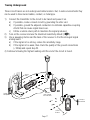
Test Lead Kit(TL-956)
Acompletetestleadkitissuppliedforusewiththetransmitter:
1. TLOP-956OutletPlugAdapter
for plugging into standard
120VACoutlets.
2. TLBP-956(2)BladeProngs
for inserting into a separate
outletwitharemoteneutral
conductorasareturnpath.
3. TLGP-956GroundProngfor
inserting into a separate outlet
withremotegroundconductor
asareturnpath.
4. TLAC-956(2)AlligatorClips
forconnectingdirectlytobare
wires and grounding points.
5. TLA1-956(2)3’LeadAdaptersforusewithaboveclipsandprongstoconnecttobare
wires and grounding points.
6. TLA2-95625’LeadAdapterforusewithaboveclipsandprongstoconnecttoremote
returnpaths.
123
46
5

Page 9
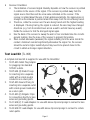
SureTrace™
1
2
4
5
367
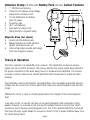
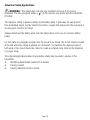
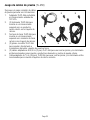
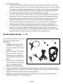
Inductive Clamp (IC-958)with Battery Pack (BP-958) Callout Features
1. 1”(25mm)JawOpening.
2. Powerfulcoilinducesalowvoltage
signal onto a closed circuit.
3. 6’cordattachestothebattery
packforpower.
4. Protectivecase.
5. (8)C-cellbatteries.
6. Inputjackforclampcord.
7. Hangmountformagneticstrap.
Magnetic Strap (not shown)
• Hooksontothebatterypack.
• Magnetattachestometalcabinets,
panels,electricalboxes,etc.
• Velcrostrapwrapsaroundandhangs
fromnon-magneticobjects.
Theory of Operation
Thetracerconsistsofatransmitterandareceiver.Thetransmitterproducesaunique
signalontothecircuittobetraced.Thereceiverdetectsthisuniquesignalwhenplacedin
theproperorientationtothewiresbeingtracedorbreakersbeingidentified.Thereceiver
providesanumericvalueandavariablepitch/tonethatincreaseasthesignalbecomes
stronger.
Thetransmittersendsa32kilohertz,fixed-amplitude,time-modulatedsignalthatinjectsa
voltageontothecircuittobetraced,whichtheninducesanelectromagneticfieldontothe
circuit.
Whether the circuit is open or closed greatly affects the strength of the electromagnetic
field.
Inanopencircuit,nocurrentcanflow,sotheelectromagneticfieldproducedismuch
weaker.However,inaclosedcircuit,theinjectedvoltageinducesacurrentflow,which
producesamuchstrongerelectromagneticfield.Thisistheoptimalmethodfortracingas
thismuchstrongersignalallowsthereceivertodetectitfromagreaterdistanceawayfrom
thecircuitbeingtraced.

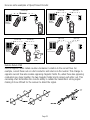
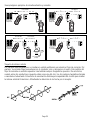
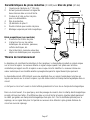
HerearesomeexamplesofOpen/ClosedCircuits:
RemoteReturnPath
Electromagneticfieldsradiatecounter-clockwiseinrelationtothecurrentflow.For
example,currentflowsoutonahotconductorandreturnsontheneutral.Thischangein
oppositecurrentflowalsocreatesopposingmagneticfields.So,whenthesetwoopposing
conductorsareclosetogether,thetwomagneticfieldstendtocanceleachotherout.This
cancelingeffectdiminishesthecircuit’sabilitytoradiatethetransmitter’sstrongsignal
makingitmoredifficultforthereceivertodetectthesignal.
Page 10
Breaker
Energized
Breaker
Energized
Breaker
Energized
LightOn
(Load)
Breaker
De-Energized
ClosedLoop
ClosedLoop ClosedLoop
ClosedLoop OpenLoop
OpenLoop OpenLoop
Stronger
Stronger Stronger
Stronger Weaker
Weaker Weaker

Page 11
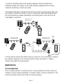
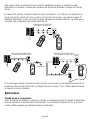
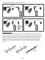
Toavoidthecancelingeffectoftheopposingmagneticfieldsandoptimizethe
transmittedsignal,theconductortobetracedshouldbeseparatedfromthereturn
conductorbyutilizingaremotereturnpath.
Thesimplestmethodistousethe25’testleadtoconnecttoaremotereturnpath,such
asaneutralorgroundfromanothercircuitorawaterpipe.Whenidentifyingbreakers,
thehotandneutralarealreadyseparatedattheelectricalpanelsotheuseoftheAC
outlet adapter is sufficient.
Ifunsurethattheremotereturnpathchosenisagoodone,useamultimetertomeasure
theresistancebetweenthecircuitneutralandtheremotereturnpath.If>100Ω,a
differentreturnpathshouldbeselected.
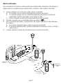
Applications
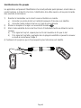
Pre-test Operation
Priortofindingabreakerortracingacircuit,itisgoodpracticetotestthereceiverby
holdingitnearthepoweredtransmitterorinductiveclamp.Anumericindicationof“99”
andstrongaudiblesoundensuresthatitisworkingproperly.
WeakSignalSetup
SignalsCancel
StrongSignalSetup
NoSignalCanceling StrongSignalSetup
NoSignalCanceling
Circuit
under
test
SeparateCircuit
WaterPipe

Page 12
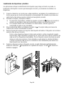
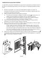
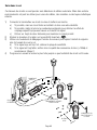
Locating Circuit Breakers and Fuses
Applicationsincludeidentifyingthebreakerthatprotectsthecircuitundertest,findingthe
correctbreakertode-energizethecircuit,andlabelingabreakerpanel.
1) Connectthetransmittertothecircuitthatneedstobeidentifiedandpoweriton.
Theprocedureisthesamewhetherthecircuitisenergizedorde-energized.But,a
muchstrongersignalisproducedusinganenergized(closed)circuit.
2) Turnonthereceiverandgotothepanel.
a) Ifmorethanonepanelexists,setthereceivertomodeandtouchthenose
toeachpanelcoveruntilthepanelwiththestrongestsignalisidentified.
b) Ifthereceiverisdetectingmorethanonepanelwithastrongsignal,reducethe
sensitivityrangeandrepeatthestepabove.
3) Openthepanelcover,setthereceivertoBreakermode.Thereceivershouldbe
positionedonitssidetoorientatetheantennaproperly.
4) Slidethenoseofthereceiverdowneachbreakerinthepanel.Thebreakerwiththe
highestnumericreadingisthecorrectbreaker.
Iftwoormorebreakershavethesamenumericvalues,tipthenoseofthe
receiverupandthendownat45ºanglesandnotethenumericvaluesoneach
ofthequestionablebreakers.Onlythecorrectbreakerwillshowastrongsignal
inallpositions.Or,pullthepanelcover,andplacethenoseoneachofthe
individualhotwiresforamorecertaindetermination.
5) Whenthecorrectbreakeristripped(opened),thesignalwilldropsignificantly.And,
thewilldisappearfromthereceiver’sdisplay.TheLEDonthetransmitterwill
also turn off.

Tracing Wires
Applicationsincludefindingthelocationsofcablerunsandidentifyingotherdevicesand
loadsonthecircuit.
1) Connectthetransmittertothecircuittobetracedandpoweriton.
a) Foroptimaltracing,leavethecircuitenergizedtocreateaclosedloop.
b) Ifthecircuitisde-energized,thenconnecttransmittertotheneutralandground
conductors to create a closed loop.
2) Turnonthereceiverandusethedefaultmaximumsensitivity().
3) Startingseveralfeetfromthetransmitter,useasweepingmotionandthebackofthe
receivertofindthestrongestsignallocationbehindthewall,abovetheceiling,orunder
thefloor.
a) Ifthesignalistoostrong,reducethesensitivityrange.
b) Ifthesignalistooweak,utilizearemotereturnpathforthetransmitter.Then,reduce
thesensitivityrangeonthereceiverandrepeatstep#3.
4) Continuefollowingthehighestreadinguntiltheendofthecircuitisfound.
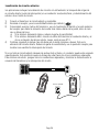
Tracing Low Voltage and Data Cable
Applicationsincludetracing
coax,twistedpair,Cat5,alarm
andtelephonewire.
Followtheinstructionsfor
TracingWiresbehindwallsusing
thede-energizedmethodanda
remotegroundforareturnpath.
Page 13
StrongerSignal
Connectto
Ground
(ShieldofCoax)
Ifpossible,ground
thefarendofthe
cableshield.
OR
WeakerSignal

Finding Opens
Applicationsincludelocatingdeadcircuits,findingthesourceofanopen(brokenpoint)in
ahot/neutral/groundconductor,anddeterminingtheendofacircuitrun.
1) Connectthetransmittertotheopencircuitandpoweriton.
2) Turnonthereceiverandusethedefaultmaximumsensitivity.
3) Startingseveralfeetfromthetransmitter,useasweepingmotionandthebackofthe
receivertofindthestrongestsignallocationbehindthewall,abovetheceilingor
underthefloor.
a) Ifthesignalistoostrong,reducethesensitivityrange.
b) Ifthesignalistooweak,connectoneleadofthetransmitterintotheopenconductor
andconnecttheotherleadtoaremotereturnpath.Then,repeatstep#3.
4) Continuefollowingthehighestreadinguntilthesignalstartstofalloff.Thisisthe
locationoftheopen.Reducethesensitivityrangeandusethenoseofthereceiverto
pinpointtheopenonthecircuit.
Iftheopenisnotfoundaftertracingthelengthoftherun,theconductormaybecapacitively
coupled.Thisconditioncausesasignalbleed-offontotheotheradjacentconductors.To
removethiseffect,groundtheadjacentconductorsandminimizethedistancebetweenthe
transmitterconnectionandtheopen.
Page 14
SeparateCircuit

Finding Shorts
Applicationsincludedeterminingcausesofbreakerstripping,fusesblowing,andcurrent
leakingonthegroundconductor.Thetracerlocatestheoriginofthegroundfaultordead-
shortinthesecircuits.
1) Connectthetransmittertotheshortedcircuitandpoweriton.
a) Oneleadshouldbeconnectedtothefaultedconductorandtheotherleadto
ground.
b) Ifthegroundfaultisinmetallicconduit,thentheconduitistheground.
c) Ifpossible,groundtheadjacentconductors.
2) Turnonthereceiverandusethedefaultmaximumsensitivity().
3) Startingseveralfeetfromthetransmitter,useasweepingmotionandthebackofthe
receivertofindthestrongestsignallocationbehindthewall,abovetheceiling,or
underthefloor.
c) Ifthesignalistoostrong,reducethesensitivityrange.
d) Ifthesignalistooweak,connectoneleadofthetransmitterintotheopenconductor
andconnecttheotherleadtoaremotereturnpath.Then,repeatstep#3.
4) Continuefollowingthehighestreadinguntilthesignalstartsweakening.Thisisthe
pointofthefaultasthesignalflowstogroundinsteadofcontinuingstronglydown
thehotconductor.Reducethesensitivityrangeandusethenoseofthereceiverto
pinpointthesourceofthefault.
Page 15
Tripped
Circuit
Breaker
StrongerSignal WeakerSignal
Short
toGround
Breaker
Panel

Page 16
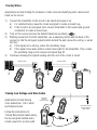
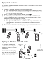
Sorting Bundled Wires
Applicationsincludeidentifyingaspecificcircuitamongstseveralcircuitsinafilled
conduit,sortingwiresinawireharness,identifyingcoaxcableandtwistedpaircableina
terminationbox.
1) Connectthetransmittertothecircuittobetracedandpoweriton.
a) Cliponetestleadtotheknownendofthewiretobetracedoridentified.
b) Cliptheothertestleadtoaremotereturnpath.
2) Turnonthereceiverandsetittotheleastsensitivity().
3) Gototheotherendofthewirerunandsortouttheindividualwireusingthenoseof
thereceiver.
a) Ifthesignalistoostrong,separatethewiresmorefromthebundlewhentesting.
b) Ifthesignalistooweak,thenincreasethesensitivityrangeonthereceiverand
repeatstep#3.
4) Continuesortinguntilthewirewiththehighestreadingisidentified.

Page 17
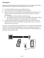
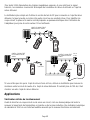
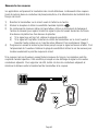
Tracing Underground
Thesecircuittracersarenotundergroundcablelocators.But,insomeenvironmentsthey
canbeusedtotraceburiedcables,conduit,ormetalpipe.
1) Connectthetransmittertothecircuittobetracedandpoweriton.
a) Ifpossible,createaclosedcircuitbygroundingtheotherend.
b) Ifpossible,groundtheadjacentconductorstoeliminatecapacitive-coupling
effectsthatcancausesignalbleed-over.
c) Utilizearemotereturnpathtomaximizethesignalproduced.
2) Turnonthereceiverandusethemaximumsensitivitydefault().
3) Useasweepingmotionandthebackofthereceivertofindthestrongestsignal
underground.
a) Ifthesignalistoostrong,reducethesensitivityrange.
b) Ifthesignalistooweak,thencheckthequalityofthegroundconnections
(<100Ω)andrepeatstep#3.
4)Continuefollowingthehighestreadinguntiltheendofthecircuitisfound.
OR
Service
Panel
Outside
Receptacle
Keeptwo
pathsseparate
fromeachother
25Feet
Distance
Connectto
GroundRod

Page 18
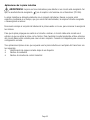
Inductive Clamp Applications
WARNING: Theclampdoesnothaveanyindicatorstosenseifacircuitis
energized.Thelineenergizedfeature()onthereceiveronlyworkswiththetransmitter
(TR-955).
Theinductiveclampispoweredsolelybythebatterypack.Itgeneratesitsownspecific,
timemodulatedsignal,andbytransformeraction,couplesthatsignalontotheenergizedor
de-energizedcircuittobetraced.
Alwaysdisconnectthebatterypackfromtheclampwhennotinusetoconservebattery
power.
Fortheclamptopropagateasignalontothecircuittobetraced,thecircuitmustbeclosed
attheendwheretheclampisapplied,ataminimum.Tomaximizethesignalproduced,
bothendsofthecircuitshouldbeclosedtocreateacompleteloop.Refertothediagrams
for proper setup.
Threetypicalapplicationswheretheinductiveclampmaybeusedinreplaceofthe
transmitter:
• Identifyingdownstreamloadsfromabreaker
• Tracingconduit
• Tracingindustrialcontrolcircuits

Page 19
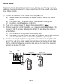
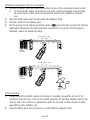
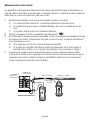
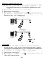
Identifyingdownstreamloadsfromabreaker.
1) Removethepanelcoverandclamparoundthehotwireoftheenergized(closed)circuit.
• Tomaximizethesignal,closethefarendofthecircuitbyplugginginandturning
onaworklightorotherloadintothefurthestoutlet;hence,makingacomplete
loop.
2) Hangthebatterypackontothepanelwiththemagneticstrap.
3) Plugtheclampintothebatterypack.
4) Setthereceivertothehighestsensitivitymode()andtracethecircuittothefurthest
outletwhileidentifyingalloutletsandloadsconnectedtothecircuit.IftheReceiveris
saturated,reducethesensitivityrange.
TracingConduit.
1) Clamparoundthemetallicconduittobetraced.Ifpossible,groundthefarendofthe
conduittoclosetheloop.Thiscanbecreatedusingthe25’leadandalligatorclipstoclip
ontotheendoftheconduitorelectricalboxwithoneclipandaremoteneutralorwater
pipewiththeotheralligatorclip.
2) Hangthebatterypackontothepanelorconduitwiththemagneticstrap.
WeakerSignal-Open
StrongerSignal-Closed
LightOn
(Load)
Breaker
Energized
Breaker
Energized

Page 20
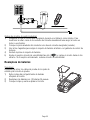
3) Plugtheclampintothebatterypack.
4) Setthereceivertothehighestsensitivity()modeandtracetheconduit.Ifthe
Receiverissaturated,reducethesensitivityrange.
Tracingindustrialcontrolcircuits.
1) Ensurethatthecircuitisenergized(closedatthepanel)ataminimum.Tomaximizethe
signal,closetheotherendofthecircuitbyturningonaload,suchasamotororpump.
2) Clamparoundthehotwireofthisenergized(closed)circuit.
3) Usethemagneticstraptohangthebatterypackontothepanelor themotorcontrol
cabinet.
4) Plugtheclampintothebatterypack.
5) Setthereceivertothehighestsensitivity()modeandtracethecircuittotheother
end.Ifthereceiverissaturated,reducethesensitivitymode.
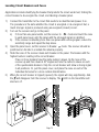
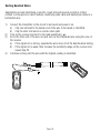
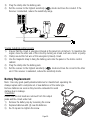
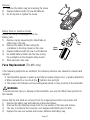
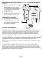
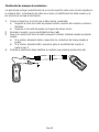
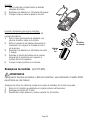
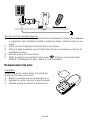
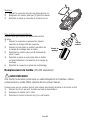
Battery Replacement
Note:Useonlygoodqualityalkalinebatteriesformaximimumoperatinglife.
Alwaysreplacewithacompletesetofnewbatteriesofthesametype.
Removebatteriesassoonastheybecomeexhaustedtoavoid
damageduetoleakage.
Transmitter:
Ensurethatthetestleadsareremovedfromtheoutput
jacksandthecircuitundertest.
1) Removethebatterycapbylooseningthescrew.
2) Replacebatterieswith(4)newAAbatteries.
3) Re-fitcapandre-tightenthescrew.
La page charge ...
La page charge ...
La page charge ...
La page charge ...
La page charge ...
La page charge ...
La page charge ...
La page charge ...
La page charge ...
La page charge ...
La page charge ...
La page charge ...
La page charge ...
La page charge ...
La page charge ...
La page charge ...
La page charge ...
La page charge ...
La page charge ...
La page charge ...
La page charge ...
La page charge ...
La page charge ...
La page charge ...
La page charge ...
La page charge ...
La page charge ...
La page charge ...
La page charge ...
La page charge ...
La page charge ...
La page charge ...
La page charge ...
La page charge ...
La page charge ...
La page charge ...
La page charge ...
La page charge ...
La page charge ...
La page charge ...
La page charge ...
La page charge ...
La page charge ...
La page charge ...
La page charge ...
La page charge ...
La page charge ...
La page charge ...
La page charge ...
La page charge ...
La page charge ...
La page charge ...
-
 1
1
-
 2
2
-
 3
3
-
 4
4
-
 5
5
-
 6
6
-
 7
7
-
 8
8
-
 9
9
-
 10
10
-
 11
11
-
 12
12
-
 13
13
-
 14
14
-
 15
15
-
 16
16
-
 17
17
-
 18
18
-
 19
19
-
 20
20
-
 21
21
-
 22
22
-
 23
23
-
 24
24
-
 25
25
-
 26
26
-
 27
27
-
 28
28
-
 29
29
-
 30
30
-
 31
31
-
 32
32
-
 33
33
-
 34
34
-
 35
35
-
 36
36
-
 37
37
-
 38
38
-
 39
39
-
 40
40
-
 41
41
-
 42
42
-
 43
43
-
 44
44
-
 45
45
-
 46
46
-
 47
47
-
 48
48
-
 49
49
-
 50
50
-
 51
51
-
 52
52
-
 53
53
-
 54
54
-
 55
55
-
 56
56
-
 57
57
-
 58
58
-
 59
59
-
 60
60
-
 61
61
-
 62
62
-
 63
63
-
 64
64
-
 65
65
-
 66
66
-
 67
67
-
 68
68
-
 69
69
-
 70
70
-
 71
71
-
 72
72


Ideal 61-955 SureTrace Circuit Tracers Manuel utilisateur
- Catégorie
- Testeurs de réseau câblé
- Taper
- Manuel utilisateur