Pacific energy FP25 LE Zero-Clearance FireplaceLIMITED INVENTORYCheck with your local dealer. Manuel utilisateur
- Catégorie
- Cheminées
- Taper
- Manuel utilisateur
Ce manuel convient également à

190423-36 FP25 LE 100003890
INSTALLATION
AND OPERATING
INSTRUCTIONS
SAFETY NOTICE
If this Fireplace is not properly installed,
a house re may result. For your safety,
follow the installation instructions.
Contact local building or re ofcials
about restrictions and installation
inspection requirements in your area.
IMPORTANT:
THESE INSTRUCTIONS ARE TO
REMAIN WITH THE HOMEOWNER.
MODEL:
FP25 LE,
FP25AR LE
SERIAL #
Meets the U.S.Environmental Protection
Agency's 2020 Particulate Emission Standards
for Cord Wood
Visit www.pacificenergy.net for the most recent version of this manual
TESTED and LISTED to;
CAN/ULC S610 AND UL127

PLEASE SAVE THESE INSTRUCTIONS
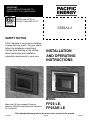
This manual describes the installation and operation of the Pacic Energy, FP25LE/FP25 AR LE wood burning Fireplace.
SAFETY NOTICE: If this heater is not properly installed, a house re may result. For your safety, follow the installation
instructions. Contact local building or re ofcials about restrictions and installation inspection requirements in you area.
Please read this entire manual before you install and use your new room heater. Failure to follow instructions may result
in property damage, bodily injury, or even death.
Contents
Table of Contents ............................................................ 2
Rating Label .................................................................... 3
Efciency and BTU Output ....................................... 3
Safety .............................................................................. 4
Curing of the Paint Finish .......................................... 5
Operation ......................................................................... 6
Wood Selection ......................................................... 6
DO NOT BURN THESE MATERIALS ......................... 6
How to Test Your Wood ............................................. 7
Lighting a Fire ............................................................ 7
Normal Operation ...................................................... 7
Restarting After Extended or Overnight Burns ......... 8
Over Firing ................................................................. 8
Proper Draft ............................................................... 8
Maintenance Checks ....................................................... 9
Weekly: ...................................................................... 9
Monthly ..................................................................... 9
When Cleaning the Chimney System: ....................... 9
Maintenance .................................................................. 10
Disposal of Ashes ................................................... 10
Door Glass/Gaskets ................................................ 11
Blowers: .................................................................. 11
Bafe: ...................................................................... 11
Bafe Removal: ....................................................... 12
Secondary Air Box Cleaning ................................... 12
Blower Replacement ..................................................... 13
Fireplace Installation ...................................................... 14
Locating your Fireplace ........................................... 14
Mobile Home Installation notes: ............................. 14
Crate Removal ........................................................ 14
Dimensions .................................................................... 15
Fireplace Clearances and Dimensions .................... 15
Minimum Framing Dimensions ...................................... 16
Framing Kit Installation .................................................. 17
Assembly ................................................................. 17
Installing the unit into the chase ............................. 17
Chimney Installation ...................................................... 18
Offset Chimney: ..................................................... 19
Masonry Chimney: .................................................. 20
Combustion Air .............................................................. 21
Installation: .............................................................. 21
Convection Blower Wiring ............................................. 22
Ember Protection .......................................................... 23
Safety Strip ............................................................. 23
Ember Protector ...................................................... 23
Option: Remote Heat Duct Kit Installation .................... 24
HEAT DUCT Replacement Parts ................................... 25
Ducting Options ............................................................ 26
Duct Installation ...................................................... 27
Remote Heat Kit Wiring ................................................. 29
Finshing The Chase ....................................................... 30
Mantel and Finishing Clearances .................................. 31
Mantel Clearances and Dimensions ....................... 31
Firebrick Installation Instructions ................................... 32
Rating Label Location & Access ..................................... 33
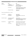
Troubleshooting ............................................................. 34
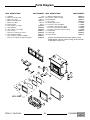
Parts Diagram .................................................................. 35
Table of Contents
HOT GLASS WILL CAUSE
BURNS.
DO NOT TOUCH GLASS UNTIL
COOLED.
NEVER ALLOW CHILDREN TO
TOUCH GLASS.
!
WARNING
WARNING: this product can expose you to chemicals
including ceramic bers, which are known to the state of
California to cause cancer,and to carbon monoxide, which
is known to the state of California to cause birth defects or
other reproductive harm.
For more information go to www.p65warnings.ca.gov.
This warning is applicable to all
PACIFIC ENERGY FIREPLACE
PRODUCTS
2FP25 LE 190423-36
100003890

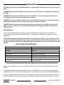
EPA Certied Emissions 1.4 grams per hour
LHV Tested Efciency 1 72%
HHV Tested Efciency 2 67%
EPA BTU Output 3 11,000 to 51,500 btu/hr
Peak BTU/Hr Output 4
Maximum Wood Length 17 inches
Ideal Wood Length 16 inches
Fuel Seasoned Cord wood
1 Weighted Average Lower Heating Value (LHV) efciency as
tested using CSA B415 Performance testing of solid-fuel-
burning heating appliances. LHV assumes the moisture is
already in a vapour state so there is no loss of energy
2 Weighted Average Higher Heating Value (HHV) efciency
as tested using CSA B415 Performance testing of solid-fuel-
burning heating appliances. HHV includes the energy required
to vaporize the water in the fuel
3 The range of BTU outputs is based on efciency using CSA
B415 Performance testing of solid-fuel-burning heating appli-
ances and burn rates from the low and high EPA tests using
Douglas Fir dimensional lumber.
Efficiency and BTU Output
This heater meets the U.S. Environmental Protection Agency's 2020 Cord wood emission limits for wood
heaters sold after May 15, 2020 Tested to ASTM 3053.
Under specic test conditions this heater has been shown to deliver heat at rates ranging from 11,000 to
51,500Btu/hr. Emissions testing was performed by PFS-TECO Inc.
For instructions on locating and accessing the Rating label, see page 33.
Rating Label
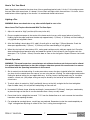
CLEARANCES TO SIDE AND BACK STANDOFFS/ DÉGAGEMENTS 0 in. / 0 mm
C. CORNER TO SIDEWALL/ COIN AU MUR LAT. 3.1 in. / 79mm
D. FRAMING OPENING/ OVERTURE DE CADRAGE 56 in./1.42m
E. CEILING TO UNIT/ DU PLAFOND AU FOYER 38-3/4 in. / 986mm
NON-COMBUSTIBLES ONLY IN THE SPACE ABOVE UNIT TO CEILING, NOT INCLUDING
APPROVED FRAMING / NON-COMBUSTIBLES SEULEMENT AU-DESSUS FOYER À PLAFOND
F. BASE OF UNIT TO MANTEL/ BASE DE L’UNITÉ AU MANTEAU
G. EMBER PROTECTION FROM FRONT OF UNIT/ PROTECTEUR de PLANCHER À
L’AVANT DU FOYER 18 in. / 457 mm
H. EMBER PROTECTION TO SIDE OF UNIT/ PROTECTEUR de PLANCHER AU CÔTÉ
DU FOYER 8 in./203 mm
IN USA: (Type 1 fl oor protector - approved to UL1618)Equal to Minimum 20GA steel
DO NOT REMOVE THIS LABEL/ NE RETIREZ PAS CETTE IQUETTE
MINIMUM CLEARANCES TO COMBUSTIBLE MATERIALS/ DÉGAGEMENTS MINIMUMS AUX MATÉRIAUX COMBUSTIBLES
SN-
100003892 200320
MANTEL HEIGHT MUST BE MEASURED FROM THE BASE OF THE UNIT AS FOLLOWS:
48 1/8 in.(1.22m) FOR ALL MANTEL DEPTHS FROM 2”(51mm) TO 12”(305mm).///
LA HAUTEUR DU MANTEAU, MESURÉE DE LA BASE DE L’APPAREIL, DOIT ÊTRE DE 48-1/8po (1,22 m)
POUR LES MANTEAUX AYANT UNE PROFONDEUR DE 2 po (51 mm) À 12 po (305 mm).
***
***
MODEL/ MODÈLE: FP25 LE FP25AR LE
LISTED FACTORY BUILT FIREPLACE, also for use in Mobile Home.
CERTIFIED TO / CERTIFIÉ POUR:
ULC S610-M87 AND UL 127-2011 for CANADA AND U.S.A.
ETL#4001507
Refer to Intertek’s Directory of Building Products for detailed information
•
•
LE SYSTÈME DE CHEMINÉE DOIT ÊTRE HOMOLOGUÉ COMME SUIT : AU CANADA - CHEMINÉE HOMOLOGUÉE ULC-S-629,
LE SYSTÈME DE CHEMINÉE DOIT ÊTRE HOMOLOGUÉ COMME SUIT : AU CANADA - CHEMINÉE HOMOLOGUÉE ULC-S-629,
• INSTALLEZ ET UTILISEZ SELON LES INSTRUCTIONS D’INSTALLATION ET D’UTILISATION FOURNIES AVEC LE FOYER.
• LES PARTIES DU FOYER INCORPORANT DES CONDUITS CHAUDS OU FROIDS DOIVENT ÊTRE ENCHÂSSÉES, CONFORMÉMENT AUX IN-
STRUCTIONS D’INSTALLATION ET D’UTILISATION FOURNIES AVEC LE FOYER.
• CONTACTEZ LES AGENTS LOCAUX DU CODE DU BÂTIMENT OU DU SERVICE-INCENDIE POUR LES RESTRICTIONS, PERMIS
D’INSTALLATION ET EXIGENCES D’INSPECTION DANS VOTRE RÉGION.
• NE RACCORDEZ PAS CE FOYER À UN CONDUIT DE CHEMINÉE DESSERVANT UN AUTRE APPAREIL.
• NE PAS OBSTRUER PAS LES OUVERTURES DEVANT LE FOYER, NI RESTREINDRE L’ALIMENTATION D’AIR NÉCESSAIRE POUR LE FONC-
TIONNEMENT NORMAL DU FOYER, TEL QUE SPÉCIFIÉ DANS LES INSTRUCTIONS D’INSTALLATION ET D’UTILISATION FOURNIES AVEC
L’APPAREIL. LA PROVISION INADEQUATE D’AIR POUR COMBUSTION, MAI DE VENTILATION ET DILUTION A POUR RESULTAT L’OPERATION
DANGEREUSE DE CECI ET AUTRES APPAREILS.
• VOIR LE CODE DU BÂTIMENT LOCAL ET LES INSTRUCTIONS DU FABRICANT, POUR LES PRÉCAUTIONS EXIGÉES LORSQU’UNE CHEMINÉE
TRAVERSE UN MUR OU PLAFOND EN MATÉRIAUX COMBUSTIBLES.
• REMPLACEZ LA VITRE SEULEMENT PAR UNE VITRE EN CÉRAMIQUE. • LA SOUFFLERIE CLASSEMENT ELECTRIQUE 115V, 60 Hz, 1.1AMP
• CETTE CHEMINEE n’A pas ETE ESSAYEE AVEC UN UNVENTED JOURNAL DE GAZ A REGLE. POUR REDUIRE LE RISQUE DE FEU OU BLES-
SURE, LE PAS INSTALLE UN UNVENTED JOURNAL DE GAZ A REGLE DANS CHEMINEE.
• UTILISEZ SEULEMENT AVEC LA PORTE DE CHARGEMENT FERMÉE. NE L’OUVREZ QUE POUR ALIMENTER LE FEU.
• CE FOYER PEUT ÊTRE INSTALLÉ DANS UNE MAISON PRÉFABRIQUÉE. UTILISER DU BOIS SOLIDE SEULEMENT.
• POUR COMBUSTIBLE SOLIDE SEULEMENT.
• COMPOSANTS OPTIONNELS: KIT DE CONDUITS DE DISTRIBUTION DE CHALEUR (PIÈCE no WODC.RHKA).
• UTILISEZ LES COMPOSANTS SPÉCIFIÉS DANS LES INSTRUCTIONS D’INSTALLATION DE PACIFIC ENERGY.
MANUFACTURED BY/ FABRIQUÉ PAR :
PACIFIC ENERGY FIREPLACE PRODUCTS
LTD.
2975 ALLENBY RD., DUNCAN, BC V9L 6V8
MADE IN CANADA
/ FABRIQUÉ AU CANADA
U.S. ENVIRONMENTAL PROTECTION AGENCY
Certifi ed to comply with 2020 particulate
emission standards,
using Cordwood.
Tested to ASTM 3053 1.4g/hr.
DATE OF MANUFACTURE
•
•
ALSO FOR USE IN MANUFACTURED HOMES WITH SOLID WOOD FUEL ONLY
• INSTALL AND USE IN ACCORDANCE WITH THE INSTALLATION AND OPERATING INSTRUCTIONS SUPPLIED WITH THE APPLIANCE
• AREAS OF THE FIREPLACE INCORPORATING WARM OR COLD AIR DUCTS SHALL BE ENCLOSED IN ACCORDANCE WITH THE INSTALLA-
TION AND OPERATING INSTRUCTIONS SUPPLIED WITH THE APPLIANCE.
• CONTACT LOCAL BUILDING OR FIRE OFFICIALS ABOUT RESTRICTIONS, INSTALLATION PERMIT AND INSPECTION IN YOUR AREA.
• DO NOT CONNECT THIS UNIT TO A CHIMNEY FLUE SERVING ANOTHER APPLIANCE
• DO NOT OBSTRUCT THE OPENINGS IN FRONT OF THE FIREPLACE OR OTHERWISE RESTRICT SUPPLY AIR NECESSARY FOR NORMAL
FIREPLACE OPERATION AS SPECIFIED IN INSTALLATION AND OPERATING INSTRUCTIONS SUPPLIED WITH THE APPLIANCE. INADEQUATE
AIR SUPPLY FOR COMBUSTION, VENTILATION AND DILUTION MAY RESULT IN DANGEROUS OPERATION OF THIS AND OTHER APPLIANCES.
• CHIMNEY SYSTEM MUST BE LISTED TO:
ULC S-629 IN CANADA / UL-103 HT IN USA -
ULC S-629 IN CANADA / UL-103 HT IN USA - SEE LOCAL BUILDING CODE AND MANUFACTURER'S
INSTRUCTIONS FOR PRECAUTIONS REQUIRED WHEN PASSING A CHIMNEY THROUGH A COMBUSTIBLE WALL OR CEILING.
• OPTIONAL COMPONENTS: REMOTE HEAT KIT PART# WODC.RHKA.
• USE SOLID WOOD FUEL ONLY. OPERATE ONLY WITH FEED DOOR CLOSED. OPEN TO FEED FIRE ONLY.
• BLOWER ELECTRICAL RATING 115V, 60HZ, 1.1AMP • REPLACE GLASS ONLY WITH 5mm CERAMIC GLASS.
• DO NOT USE OR INSTALL COMPONENTS OR PRODUCTS NOT SPECIFIED IN PACIFIC ENERGY INSTALLATION INSTRUCTIONS.
• DO NOT USE A FIREPLACE INSERT OR OTHER PRODUCTS NOT SPECIFIED FOR USE WITH THIS PRODUCT.
• THIS FIREPLACE HAS NOT BEEN TESTED WITH AN UNVENTED GAS LOG SET. TO REDUCE RISK OF FIRE OR INJURY, DO NOT INSTALL AN
UNVENTED GAS LOG SET INTO FIREPLACE.
• THIS WOOD HEATER NEEDS PERIODIC INSPECTION AND REPAIR FOR PROPER OPERATION.
• - CONSULT THE OWNER’S MANUAL FOR FURTHER INFORMATION.
• IT IS AGAINST FEDERAL REGULATIONS TO OPERATE THIS WOOD HEATER IN A MANNER INCONSISTANT WITH THE OPERATING
INSTRUCTIONS IN THE OWNER’S MANUAL.
C
D
E
G
F
CAN.
U.S.A.
H
H
3
FP25 LE 190423-36 100003890

Safety
Instruct all members of your family on the safe operation of the heater. Ensure they have enough
knowledge of the entire system if they are expected to operate it. Stress the section on chimney fires
and the importance of following the steps outlined "In the Event of aChimney Fire".
NOTE: SMOKE AND CARBON MONOXIDE DETECTORS MAY BE REQUIRED TO BE INSTALLED IN THE
AREA WHERE THE HEATER IS INSTALLED. Even if not requred, we strongly recommend that they be
installed in the area where the heater is installed
If smoke detectors have been previously installed, you may notice that they are operating frequently. This may
be due to curing of stove paint or fumes caused by accidentally leaving the re door open. Do not disconnect
the detectors.
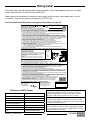
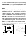
Chimney Smoke and Creosote Formation
When wood is burned slowly, it produces tar and other organic vapours, which combine with expelled
moisture to form creosote. The creosote vapours condense in the relatively cool chimney ue of a slow
burning re. As a result, creosote residue accumulates on the ue lining. When ignited, this creosote makes
an extremely hot re. The chimney connector and chimney should be inspected periodically (at least once
every two months) during the heating season to determine if a creosote buildup has occurred. If creosote has
accumulated (3 mm. or more), it should be removed to reduce the risk of a chimney re.
1. Highest smoke densities and emissions occur when a large amount of wood is added to a bed of hot
coals and the air inlet is closed. The heated wood generates smoke, but without ample air, the smoke
cannot burn. Smoke-free, clean burning requires small fuel loads, two or three logs at a time or 1/4 to 1/2
of fuel load and leaving the air inlet relatively wide open, especially during the rst 10 to 30 minutes after
each loading, when most of the smoke generating reactions are occurring. After 30 minutes or so, the air
inlet can be turned down substantially without excessive smoke generation. Wood coals create very little
creosote-producing smoke.
2. The cooler the surface over which the wood smoke is passing, the more creosote will be condensed.
Wet or green wood contributes signicantly to creosote formation as the excess moisture that is boiled
off cools the re, making it difcult for the tars and gases to ignite, thus creating dense smoke and poor
combustion. This moisture-laden smoke cools the chimney, compounding the problem by offering the
smoke the ideal place to condense.
In summary, a certain amount of creosote is inevitable. Regular inspection and cleaning is the solution. The
use of dry, seasoned wood and ample combustion air will help to minimize annoying smoke emissions and
creosote buildup.
Chimney Fires
The dangerous side effect of excessive creosote buildup is a chimney re. This causes much higher than
normal temperatures in the chimney and on its exterior surfaces. Temperatures inside the chimney can
exceed 2000°F (1100°C). Ignition of nearby or touching combustible material is more likely during a chimney
re. Proper clearances are critical to prevent damage during such a re.
Chimney res are easy to detect; they usually involve one or more of the following:
• Flames and sparks shooting out of the top of the chimney
• A roaring sound
• Vibration of the chimney
4FP25 LE 190423-36
100003890

Avoiding a Chimney Fire
1. Burn wood cleanly. Do not burn wet wood or turn down the unit too quickly after loading.
2. Do not let creosote build up to a point where a chimney re is possible.
3. Do not have res in the heater that may ignite chimney res. These are excessively hot res, such as when
burning household trash, cardboard, Christmas tree limbs, or even ordinary fuel wood; (eg. with a full load
on a hot bed of coals and with the air inlet wide open for more time than is needed to completely char a
fresh fuel load.)
4. The Chimney and connector pipe should be inspected /cleaned periodically.
In The Event of a Chimney Fire
1. Prepare to evacuate to ensure everyone's safety. Have a well understood plan of action for evacuation.
Have a place outside where everyone is to meet.
2. Close air inlet on stove.
3. Call local re department. Have a re extinguisher handy. Contact your local municipal or provincial re
authority for further information on how to handle a chimney re. It is most important that you have a
clearly understood plan on how to handle a chimney re.
4. After the chimney re is out, the chimney must be cleaned and checked for stress and cracks before
starting another re. Also check combustibles around the chimney and the roof.
We strongly recommend that your chimney be inspected by professionals who are certified by one of
the following;
NFI (National Fireplace Institute®) in the United States,
CSIA (Chimney Safety Institute of America) in the United States and Canada,
WETT (Wood Energy Technology Transfer) in Canada or
APC (Association des Professionnels du Chauffage) in Quebec
WARNING: Never use chemicals or any other volatile liquid to start a fire. Do not burn garbage, or
flammable fluids such as gasoline, naptha, or engine oil.
Curing of the Paint Finish
See Stove Bright user guide. The paint on your stove must be cured at operating temperature. When burning
your stove for the rst 2-3 times, it is very important that the room be well ventilated. Open all windows and
doors. Smoke and fumes caused by the curing process may cause discomfort to some individuals.
Health Warning.
The smoke from the curing process displaces oxygen. Small children, elderly folks and persons with existing
breathing problems should vacate the area during the hot burn to avoid the discomfort of lost oxygen. The
smoke is primarily Carbon Dioxide, and therefore non-toxic but uncomfortable.
• DO NOT STORE/PLACE WOOD WITHIN THE STOVES INSTALLATION CLEARANCES, INCLUDING IN
FRONT OF THE UNIT.
5
FP25 LE 190423-36 100003890

CAUTION: Hot while in operation. Keep children, clothing and furniture away. Contact may cause skin
burns.
WARNING: Always keep loading door closed when burning. This heater is not designed for open door
burning.
WARNING: No alteration or modification of the combustion air control assembly is permitted. Any
tampering will void warranty and could be very hazardous.
WARNING: Do not use grates or andirons to elevate the fuel. Burn directly on the fire bricks. Replace
broken or missing bricks. Failure to do so may create a hazardous condition.
CAUTION: Never use gasoline, gasoline type lantern fuel, kerosene, charcoal lighter fluid or similar
liquids to start or "freshen up" a fire in this heater. Keep all such liquids well away from the heater
while it is in use.
Wood Selection
Your Fireplace is designed to burn natural wood only. Higher efciency and lower emissions generally
result when burning air-dried seasoned hardwoods, as compared to softwoods or to green or freshly cut
hardwoods.
Wood should be properly air dried (seasoned) for six months or more. Wet or "green" wood will cause
the fire to smoulder and produce large amounts of smoke and creosote. Wet wood also produces very
little heat and tends to go out often. Wood should be stored under cover away from open flame or heat
sources.
Operation
* These materials contain chlorides which will rapidly destroy metal surfaces and void warranty.
Burning these materials may result in the release of toxic fumes or render the heater ineffective and cause
smoke.
Salt water wood * Treated wood
Wet or green wood Coal/charcoal
Garbage* Solvents
Lawn clippings/yard waste Unseasoned wood
Railroad ties Manure or animal remains
Materials containing plastic Materials containing asbestos
Construction or demolition debris Materials containing rubber, including tires
Paper products, cardboard, plywood, or
particleboard.
Waste petroleum products, paints or paint thinners,
or asphalt products
DO NOT BURN THESE MATERIALS
The prohibition against burning these materials does not prohibit the use of re starters made from paper,
cardboard, saw dust, wax and similar substances for the purpose of starting a re in an affected wood heater.
Do not burn anything but wood. Other fuels, eg. charcoal, can produce large amounts of carbon monoxide, a
tasteless, odorless gas that can kill. Under no circumstances should you attempt to barbecue in this heater.
6FP25 LE 190423-36
100003890

How to Test Your Wood
Add a large piece of wood to the stove when it has a good large bed of coals. It is dry if it is burning on more
than one side within one minute. It is damp if it turns black and lights within three minutes. If it sizzles, hisses
and blackens without igniting in ve minutes it is soaked and should not be burnt.
Lighting a Fire
WARNING: Never use chemicals or any other volatile liquid to start a fire.
Never Leave The Fireplace Unattended With The Door Open
1. Adjust air control to “High” position (all the way to the left).
2. Place crumpled newspaper in the centre of the heater and crisscross with several pieces of small dry
kindling. Ignite the paper and leave the door ajar approximately 1"(25mm) - 4"(100mm) until the kindling is
fully ignited and engulfed in ame.
3. After the kindling is burnt down 50%, add 2-3 small splits or small logs 1"(25mm) diameter. Crack the
door open approximately 1"(25mm) - 2"(100mm) until the wood kindling is fully ignited.
4. When the start-up fuel is burnt down 50%, and a good coal base exists add your regular fuel. Close the
door and begin normal operation after and wood has ignited. If the fuel load is slow to ignite crack the
door open 1" to 2"(25mm - 50mm). Close the door as soon as the fuel ignites. Repeat if ames start to die
out.
Normal Operation
WARNING: This wood heater has a manufacturer-set minimum low burn rate that must not be altered.
It is against federal regulations to alter this setting or otherwise operate this wood heater in a manner
inconsistent with the operating instructions in this manual.
1. Set air control to a desired setting. If smoke pours down across the glass (waterfall effect) this indicates
you have shut the control down too soon or you are using too low a setting. The wide range control makes
nding the desired setting for your application easy. As every home's heating needs vary (ie. insulation,
windows, climate, etc.) the proper setting can only be found by trial and error and should be noted for
future burns.
2. To refuel, adjust air control to “High” position(all the way to the left), and give the re time to brighten.
Open the door slowly, this will prevent backpufng or ame roll-out.
3. Use wood of different shape, diameter and length ( recommended 17"(432mm)). Load your wood and try
to place the logs so that the air can ow between them. Always use dry wood.
4. Do not load fuel to a height that exceeds 7 1/2" from the rebox oor or in such a manner that would be
hazardous when opening the door.
5. For extended or overnight burns, unsplit logs are preferred. Remember to char the wood completely on
"High" setting before adjusting air control to the "Low" setting for overnight burn.
7
FP25 LE 190423-36 100003890

Restarting After Extended or Overnight Burns
1. Open door and rake hot embers towards the front of the heater. Add a couple of dry, split logs on top of
embers, close door.
2. Adjust air control to high and in just a few minutes, logs should begin burning.
3. After wood has charred, reset air control to desired setting.
4. To achieve maximum ring rate, set control to “High” position(all the way to the left). Do not use this set-
ting other than for starting or preheating fresh fuel loads.
Over Firing
DO NOT OVERFIRE THIS HEATER: Attempts to achieve heat output rates that exceed heater design
specifications can result in permanent damage to the heater and chimney.
Over ring can be caused by operating the unit with the door open, damage to door gaskets allowing excess
air to enter the rebox, the use of kiln dried lumber, mill ends or paper waste and prolonged or continual use
on a high burn setting.
Proper Draft
Operation with the door open can cause excessive smoke. Do not operate this unit in a manner that will
cause excessive smoke.
Draft is the force which moves air from the appliance up through the chimney. The amount of draft in your
chimney depends on the length of the chimney, local geography, nearby obstructions and other factors. Too
much draft may cause excessive temperatures in the appliance. An uncontrollable burn or a glowing red stove
part or chimney indicates excessive draft. Inadequate draft may cause backpufng into the room and plug-
ging of the chimney. Smoke leaking into the room through appliance and chimney connector joints indicates
inadequate draft.
WARNING: This unit is not designed to be operated during normal operation with the ring door open. In
addition to the obvious hazard of sparks landing on combustibles, an open re door will cause the heater to
draw excess air from the living space and possibly cause suffocation.
8FP25 LE 190423-36
100003890

Maintenance Checks
Check the following parts for damage such as cracks, excessive corrosion, burned out sections and exces-
sive warping: (See website for descriptions and more detail).
Weekly:
• Firebrick - Visual, for cracking.
• Door Gasket - sagging, placement, damage.
Monthly
• Brick rail tabs and brick rails.
• Air riser tube in the back of the rebox.
• Back side of airwash chamber.
• Bafe locking pin.
• Boost manifold cover.
When Cleaning the Chimney System:
• Top bafe board/blanket.
• Bafe.
• Top heat shield and mounting bolt.
• Bafe Gasket.
• Brick Rails.
• Manifold.
9
FP25 LE 190423-36 100003890

Maintenance
• Establish a routine for the fuel, wood burning and ring technique. Check daily for creosote buildup until
experience shows how often you need to clean to be safe.WARNING: ONLY USE MATERIALS AND
COMPONENTS SUPPLIED OR SPECIFIED BY THE MANUFACTURER WHEN DOING MAINTENANCE
OR REPLACEMENTS. DO NOT USE A FIREPLACE INSERT OR OTHER PRODUCTS NOT SPECIFIED
FOR USE WITH THIS FIREPLACE.
• Do not store wood within heater installation clearances, or within the space required for fuel loading
and ash removal. Keep the area around the heater clean and free of loose combustibles, furniture,
newspapers, etc.
• Instruct all members of your family on the safe operation of the heater. Ensure they have enough
knowledge of the entire system if they are expected to operate it. Stress the section on chimney res and
the importance of following the steps outlined, see "In The Event of a Chimney Fire" on page 5
• Inspect and clean your chimney system at the beginning of the burning season before your rst re and at
least every two months during the burning season. Inspect the interior and exterior of the pipe for defects
and/or damage. Remove and inspect the rain cap. Refer to the chimney system manufacturer’s installation
instructions for the procedure to remove and or replace any necessary components to the chimney
system.
• Maintain a distance of 48”(1.2m) to all combustible materials in the room. See also "Ember Protector" on
page 23 for the Floor Protection dimensions.
WARNING: OVER FIRING THE APPLIANCE WILL SHORTEN THE LIFE OF THE PRODUCT.
FAILURE TO RECTIFY AN OVER FIRING CONDITION CAN BE HAZARDOUS AND MAY VOID THE
MANUFACTURER’S WARRANTY.
Ash Removal
Caution: Remove ashes frequently. Embers can roll out the door and create a re hazard. Maintain a 1” to 4"
(25mm - 100mm) ash base. Ashes are to be removed only when the re has burned down and both the ashes
and heater is cold. Whenever ashes get 3 to 4 inches deep in your rebox, remove excess ashes. Leave an
ash bed approximately 1" (25 mm) deep on the rebox bottom to help maintain a hot charcoal bed for future
res. The area where boost combustion air enters the rebox must be kept clear of excessive ash buildup
which will block air ow. This area is at the front of the rebox.
Disposal of Ashes
Ashes should be placed in a metal container with a tight tting lid. The closed container of ashes should be
placed on a non-combustible oor or on the ground, well away from all combustible materials, pending nal
disposal. If the ashes are disposed of by burial in soil or otherwise locally dispersed, they should be retained
in closed container until all cinders have thoroughly cooled. Other waste should not be placed in this con-
tainer.
10 FP25 LE 190423-36
100003890

Door Glass/Gaskets
• If glass becomes darkened through slow burning or poor wood, it can be cleaned with replace glass
cleaner when the replace is cold. Never scrape with an object that might scratch the glass. The type and
amount of deposit on the glass is a good indication of the ue pipe and chimney buildup. A light brown
dusty deposit that is easily wiped off usually indicates good combustion and dry, well-seasoned wood and
therefore relatively clean pipes and chimney. On the other hand, a black greasy deposit that is difcult to
remove is a result of wet and green wood and too slow a burning rate. This heavy deposit is building up as
quickly in the chimney.
• DOOR GASKETS - The gasket used by Pacic Energy (7/8”(22mm) medium density breglass rope)
requires only light pressure to seal. This will prolong seal life. It is important that the door seal be
maintained in good condition. Periodically inspect seals and replace if necessary.
• DOOR GLASS - Replacement glass can be obtained from your dealer. Use 18” (457mm) x 10-1/4”
(260mm) x 5 mm ceramic glass only.
WARNING: DO NOT SUBSTITUTE GLASS WITH ANY OTHER TYPE MATERIAL OTHER THAN CERAMIC
GLASS
WARNING: DO NOT SLAM LOADING DOOR OR OTHERWISE IMPACT GLASS. WHEN CLOSING DOOR,
MAKE SURE THAT NO LOGS PROTRUDE TO IMPACT THE GLASS. IF THE GLASS GETS CRACKED OR
BROKEN, IT MUST BE REPLACED BEFORE USING THE FIREPLACE.
To remove broken glass,remove the door gasket. Remove the screws that holds the retainer to the door and
remove the retainer, noting position for reassembly. Remove all particles of glass. Be careful as they are very
sharp. Install new glass complete with gasket. Replace retainers, screws and gasket.
CAUTION:
DO NOT OVERTIGHTEN, TIGHTEN SCREWS HAND TIGHT
DO NOT CLEAN GLASS WHEN HOT
DO NOT USE ABRASIVE CLEANERS ON GLASS
Blowers:
It is recomended that the Blowers should be cleaned out at least once a year minimum.
1. The blowers are accessed by removing the Front Trim Panel. Lift up and pull the Front Trim away from the
unit, the blowers are located on each side of the Firebox.
2. Use a vacuum to gently remove dust and debris from the intakes and wheel of the blower.
Baffle:
• Some warping of the bafe is normal(up to 1/4” or .65cm).
• Replace if the bafe has permanent warping greater than this or has cracking or breakage.
• Please contact your Dealer if you experience any of the damage listed above. Continuing to operate your
replace with broken parts may accelerate damage to other parts
• and may void your warranty.
11
FP25 LE 190423-36 100003890

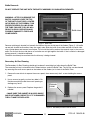
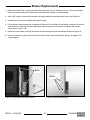
Baffle Removal:
DO NOT OPERATE THE UNIT WITH THE BAFFLE ASSEMBLY OR INSULATION REMOVED.
WARNING: AFTER YOU REMOVE THE
BAFFLE, ALWAYS COVER THE TOP
OF THE BAFFLE AIR TUBE LOCATED
IN THE REAR OF THE FIREBOX. THIS
PREVENTS DEBRIS FALLING DOWN
THE TUBE. FAILURE TO DO SO WILL
RESULT IN POOR OPERATION AND
POSSIBLE DAMAGE TO FIREPLACE
COMPONENTS.
Remove retaining pin located just beneath the bafe at the rear inside top of the rebox (Figure 1). Lift bafe
up and pull forward to disconnect from the supply tube. Slide the bale to one side and then tilt bafe side-
ways to drop down and remove from rebox. To re-install the bafe, perform the removal steps in the reverse
order. Ensure that the two side pieces of insulation are set tight against the bafe. If the insulation is damaged
during removal, it should be replaced.
The bafe should only be removed after the chimney is being cleaned.
Secondary Air Box Cleaning
The Secondary Air Box Cleaning should only be done if something has fallen down the Bafe Tube.
The secondary air box is attached to the Firebox bottom, under the Bafe Tube. The Air Box can be cleaned
by removing the small access panel on the bottom of the rebox just in front of the Bafe Tube.
1. Remove the rear bricks to expose the access panel, then remove only the 2 screws holding the access
panel.
2. Use a vacuum to gently suck out any debris. Do
Not place anything inside the access opening or
damage may occur.
3. Replace the access panel. Replace the gasket if
needed.
* MAKE SURE THE GASKET IS IN GOOD SHAPE
AND POSITIONED CORRECTLY. IF IT IS DAMAGED
THEN IT MUST BE REPLACED.
Access
cover
Figure 2: Secondary Air Box clean out cover.
Bafe tube
Figure 1: Bafe tube.
12 FP25 LE 190423-36
100003890

Blower Replacement
1. Remove the Front Trim by lifting up and pulling away from the unit. Remove the four screws securing the
back surround to the brackets and set the surround aside carefully to avoid damage.
2. With a 3/8” wrench, loosen the two bolts securing the blower mounting bracket to the unit (Figure 3).
3. Disconnect the two wires leading to the blower motor.
4. Lift the blower mounting bracket up and pull the top out rst and then lift the blower up and out to remove
from the bolts.If replacing the right side blower, then disconnect the two wires leading to the thermo-
switch at this time as well.
5. Remove the three bolts securing the blower to the mounting bracket and replace the blower (Figure 4).
6. Reverse all previous steps to reinstall the new blower. See "Convection Blower Wiring" on page 22 for
wiring diagram.
Bolts
Figure 3: Removing mounting bracket bolts.
Bolts
Figure 4: Blower mounting bolts.
13
FP25 LE 190423-36 100003890

Fireplace Installation
Warning: Under no circumstances is this heater to be installed in a makeshift or "temporary" manner. It may
be red only after the following conditions have been met.
Check with your local re/building authority for any installation code requirements and restrictions in your
area.
• The services of a competent or certied installer, (certied by the Wood Energy Technical Training program
(WETT) - in Canada, Hearth Education Foundation (HEARTH) - in U.S.A.,) are strongly recommended.
• DO NOT CONNECT THIS UNIT TO A CHIMNEY FLUE SERVING ANOTHER APPLIANCE.
• WARNING:DO NOT INSTALL IN A SLEEPING ROOM. (MANUFACTURED OR MOBILE HOME ONLY)
Locating your Fireplace
The best location to install your replace is determined by considering the location of windows, doors, and
the trafc ow in the room where the FP25 Fireplace will be located. Allow space in front of the unit for the
Ember Protection and clearances to combustibles. Take into consideration the location of the chimney. Ideally,
you should choose a location where the chimney will pass through the house without cutting oor or roof
joists. See "Fireplace Clearances and Dimensions" on page 15.
The FP25 replace may not be installed in a factory built replace unless tested with the replace.
Wind direction and magnitude can play a factor in the chimney performance. Therefore the chimney out-
let position is important when locating the replace. We recommend, whenever possible, that the chimney
should:
• Penetrate the highest part of the roof.
• Be installed as far as possible from roof offsets, trees or any other obstructions that may cause wind
turbulence or back drafts in the chimney.
• Contain the fewest number of offsets (elbows) possible.
Check the adequacy of the oor by rst estimating the weight of the replace system (approx. 500lbs(227Kg)),
plus the venting. Next measure the area the replace will occupy. Note the oor construction and consult your
local building code to determine if any additional oor support is needed. In most cases, no additional sup-
port is needed for the replace.
The FP25 replace may be installed directly on a combustible oor or on a raised base. A minimum of
84"(2.13m) measured from the base of the appliance to the ceiling is required inside the chase.
Mobile Home Installation notes:
• In the USA: the unit must be installed in accoradance with the requirements of the Department of Housing
and Urban Development (HUD)"Manufactured Home Construction and Safety.
• In Canada: the unit must be installed with access openings into the built in enclosure for inspection
purposes. The access covers must require a household tool to open.
Crate Removal
1. Carefully remove wood top and supports.
2. Remove the screws securing the replace to the pallet(4).
3. Remove from pallet bottom.
14 FP25 LE 190423-36
100003890

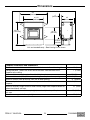
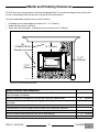
Dimensions
Fireplace Clearances and Dimensions
Distance to combustible material from the side/back standoffs and framing kit. 0" (0mm)
Ceiling clearance - both in the chase and in the room: from the base of the
replace to the ceiling.
7’ (2.13m)
Minimum distance of adjacent wall to side of replace door. 22” (560mm)
Minimum distance to (Max) 4” deep side facing from replace door opening. 11 1/2” (292mm)
Minimum width of oor protection from side of door opening. 8” (200mm)
Minimum depth of non-combustible ember protector from the front of the
replace.
16 1/2” (420mm)
Minimum chimney height: minimum total chimney height from replace bottom to
below the chimney rain cap.
15’ (4.6m)
Recommended maximum chimney height (at sea level) from top of replace to
rain cap.
35’ (10.7m)
Maximum unsupported chimney height. 20’ (6.1m)
45 1/4"
[1150 mm]
41 1/2"
[1055 mm]
10 9/16"
[269 mm]
34 3/4"
[883 mm]
24"
[610 mm]
4”
[102 mm]
56"
[1425 mm]
Unit and standoffs only - Steel framing kit not shown.
Figure 5: FP25LE Dimensions.
15
FP25 LE 190423-36 100003890

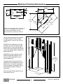
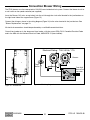
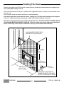
Minimum Framing Dimensions
The top front framing must be installed
as shown, (Figure 7) with no wood
framing directly in front of the chimney
system
WARNING: The replace must not be
in contact with any insulation or loose
lling material. If you are insulating the
chase, cover the insulation with drywall
or non-combustible panels. Maintain all
proper clearances.
WARNING: Drywall materials are con-
sidered combustible and theIr thick-
ness must be accounted for in your
framing dimensions.
The open volume inside the chase is
required for heat management. Do Not
build a recess, shelves or cupboards
in the area above this replace. Do not
build anything inside this Minimum
chase area.
Do Not insulate the front portion of the
chase above the unit.
24"
610mm
33 3/4"
857mm 96 5/8"
2.45m
23 7/8"
606mm
56 1/2"
1.435m
3 1/8"
79mm
68 3/8"
1.74m
56 1/2"
1.435m
68 3/8"
1.74m
9 3/8"
238mm
NOTE: The framing dimensions shown are the
minimums. Framing dimensions will need
to be adjusted accordingly to accept
drywall/wallboard if used inside enclosure.
Figure 6: FP25LE Framing Dimensions.
24”
[610mm]
56 1/2”
[1.435m]
62”
[1.575m]
7’
[2.134m]
Inside Enclosure,
from base of the
unit.
18”
[455mm] 18”
[455mm]
Figure 7: FP25LE framing enclosure.
16 FP25 LE 190423-36
100003890

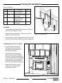
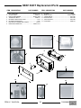
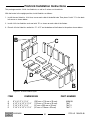
Item Part # Description Qty.
1 5049.9912 SCREW, TEKS
#8 x 1/2”(13mm)
Pkg 40
2 7746 STUD, TOP/BOTTOM
56”(1.42m)L
2
3 9093.22 STUD, CNTR
SUPPORT SIDES,
15”(381mm)L
5
4 7747 FRAMING KIT LEG 3
1/2"(89mm)L
3
Framing Kit Installation
Each Kit Contains:
Assembly
• Lay out top/bottom studs (#2) and center studs (#3) on
their sides on a large at surface.
• Using the screws provided (1), attach the framing kit
legs(4) to the bottom stud (2).
• Next, attach each center support(3) to the bottom stud(2)
and then attach the top stud(2) to the center supports(3).
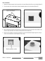
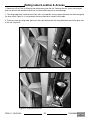
Installing the unit into the chase
• Push the Fireplace into place
(Casing must be ush with the
framing in the front) and secure if
required by local code.
• Place the Steel Framing Kit on
top of the unit with the legs down
(Figure 9). Ensure the front edge is
ush with the Fireplace and with the
chase framing. It is very important
to provide a at surface to attach
the outer non-combustible board to.
• Attach the Framing kit securely
to the chase's framing using
appropriate fasteners.
2
4
1
1
Figure 8: Framing kit parts.
Figure 9: FP25LE Chase with unit .
17
FP25 LE 190423-36 100003890

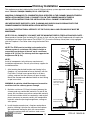
This appliance must be installed with a listed 6"(150mm) chimney system approved under the following stan-
dards: CAN-ULC S629(IN CANADA) OR UL 103HT(IN U.S.).
MAINTAIN CLEARANCES TO COMBUSTIBLES AS SPECIFIED IN THE CHIMNEY MANUFACTURERS
INSTALLATION INSTRUCTIONS. YOU MUST FOLLOW THE CHIMNEY MANUFACTURER'S
INSTALLATION INSTRUCTIONS FOR INSTALLATION OF ALL CHIMNEY COMPONENTS.
USE APPROPRIATE SUPPORTS, CAPS, FLASHING AND SHIELDS IN ACCORDANCE WITH THE
CHIMNEY MANUFACTURERS INSTALLATION INSTRUCTIONS.
CAUTION: THE STRUCTURAL INTEGRITY OF THE FLOOR, WALL AND CEILING/ROOF MUST BE
MAINTAINED.
NOTE: FOR ALL CHIMNEYS, YOU MUST USE THE MANUFACTURER'S FIREPLACE ANCHOR PLATE. -
Some brands of Anchor Plate including ICC, do not sit ush with the top of the Fireplace and will require the
installation of an Anchor Plate spacer. Part #FP30.7757. Ensure the Chimney Achor plate is fully engaged
with the Fireplace's Flue Collar when using the Anchor Plate
Spacer.
NOTE: The FP25 must be installed so the outlet of the
chimney system is a minimum 15ft (4.6m) in height as
measured from the base of the unit, up to a maximum
height of 35' (10.7m). The chimney must be supported on
lengths over 20' (6.1m).
NOTE:
Install all components to the chimney manufacturer's
installation requirements. Consult your chimney supplier for
installation advice.
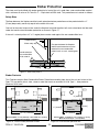
1. After locating the desired location and framing in the
replace, use a plumb bob to line up the holes with the
Flue Collar. Cut and frame square holes in all oors,
ceilings, and roof that the chimney will pass through.
Mount the restops and radiation shields to the framing
as per instructions.
WARNING: A radiation shield/firestop must be used for
each floor/wall the chimney passes through.
2. Maintain a minimum 2"(51mm) clearance between the
chimney and any combustible materials. Do not ll the
space with insulation or any other combustible material.
Install the insulation shields as required by code and all
pieces necessary to prevent contact with combustible
materials whenever passing through oors, ceilings or
attic spaces.
3. Install the pipe manufacturer's replace anchor/base
plate by inserting it into the ue collar on the replace.
We recommend sealing the joint with stove cement.
Secure the anchor plate with stainless steel screws.
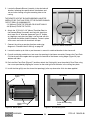
Chimney Installation
Anchor
Plate
Listed
Chimney and
Accesories
Maintain
38 3/4” [985mm]
Minimum distance
from the top of the
unit to the ceiling.
Non-Combustible
Ember Protection
Minimum distance
from the base of the
unit to the ceiling is
7’ [2.13m]
Insulation Shield
Firestop
Figure 10: FP25LE Basic installation.
18 FP25 LE 190423-36
100003890

4. Assemble the chimney sections so the nished length is resting on the manufacturer's anchor plate and
protruding through the roof. Avoid having joints between the ceiling and the roof. It is required that the
chimney connections be secured with three (3) #8x½"(12 mm) stainless screws.
5. As per the vent manufacturers instructions, Install the Roof Radiation Shield, Flashing and Storm Collar.
Be sure to maintain the vapour barrier at this point. (Seal securely.)
6. Install any exterior venting - If the chimney extends more than 5'(1.5m) above the point of contact with the
roof, then it must be secured using roof braces
7. Securely attach the rain cap and check the ashing for leaks.
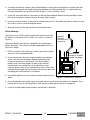
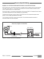
Offset Chimney:
The chimney for the FP25 can be installed with a maximum of four
45° elbows (in Canada) or four 30° elbows (in U.S.A.) as shown in
Figure 11.
Follow the chimney manufacturer's guidelines for supporting the
offsets. Reminder - The chimney must be supported after the rst
20'(6.1m) in length.
1. NOTE: Install the vertical chimney section(s) then the rst elbow
and turn it in the required direction.
2. Install the necessary chimney lengths to achieve the required
offset. Lock the chimney lengths together according to the
chimney manufacturer’s instructions. If the offset length is
made of two (2) chimney lengths or more, many chimney
manufacturers may require that you use an offset or roof
support halfway up the offset. If penetrating a wall, install a wall
radiation shield supplied by the chimney manufacturer and install
according to the manufacturer's instructions.
3. Use another elbow to turn the chimney vertically and secure the
elbow.
4. Use a plumb bob to line up the centre of the hole with the center of the ue collar on the replace. Cut a
hole for the chimney in the ceiling/oor. Frame the hole as described in Figure 10 on page 18.
5. Install all restops following the chimney manufacturer's directions.
Minimum 36”
length of Chimney
before rst elbow
Maintain
Chimney
manufacturer’s
clearances
Figure 11: FP25LE Offset Installation.
19
FP25 LE 190423-36 100003890

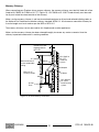
Masonry Chimney:
When connecting your Fireplace into a masonry chimney, the masonry chimney must be fully lined with a liner
listed to ULC S635, ULC S640 or UL1777 (Figure 12). ULC S629 or UL 103HT listed chimney must be used
for all parts inside the chase/outside of the chimney.
Make sure the masonry chimney is well constructed and conforms to all local and national building codes or
the National Fire Protection Association chimney standard: NFPA 211. All clearances around the chimney for
its entire length must be to code as per the NBC or NFPA 211
The masonry chimney can only be used for this replace and no other appliances.
Make sure the masonry chimney has been cleaned thoughly to remove any soot or creosote. Have the
chimney inspected to determine its working condition
Anchor
Plate
ULC-S635 or
UL-1777
listed liner
system.
16” [405mm]
Minimum distance
to the combustible
ceiling.
Mortar
Mortar
Clearances as per
Building Code or
NFPA 211
Adapter
ULC-S629 or
UL-103HT
listed Chimney
system.
Minimum 12”
chimney section
Figure 12: FP25LE Masonry Installation.
20 FP25 LE 190423-36
100003890
La page est en cours de chargement...
La page est en cours de chargement...
La page est en cours de chargement...
La page est en cours de chargement...
La page est en cours de chargement...
La page est en cours de chargement...
La page est en cours de chargement...
La page est en cours de chargement...
La page est en cours de chargement...
La page est en cours de chargement...
La page est en cours de chargement...
La page est en cours de chargement...
La page est en cours de chargement...
La page est en cours de chargement...
La page est en cours de chargement...
La page est en cours de chargement...
-
 1
1
-
 2
2
-
 3
3
-
 4
4
-
 5
5
-
 6
6
-
 7
7
-
 8
8
-
 9
9
-
 10
10
-
 11
11
-
 12
12
-
 13
13
-
 14
14
-
 15
15
-
 16
16
-
 17
17
-
 18
18
-
 19
19
-
 20
20
-
 21
21
-
 22
22
-
 23
23
-
 24
24
-
 25
25
-
 26
26
-
 27
27
-
 28
28
-
 29
29
-
 30
30
-
 31
31
-
 32
32
-
 33
33
-
 34
34
-
 35
35
-
 36
36


Pacific energy FP25 LE Zero-Clearance FireplaceLIMITED INVENTORYCheck with your local dealer. Manuel utilisateur
- Catégorie
- Cheminées
- Taper
- Manuel utilisateur
- Ce manuel convient également à