Stanley CL2i Manuel utilisateur
- Catégorie
- Niveaux laser
- Taper
- Manuel utilisateur

Please read these instructions before operating the product
CL2i
2 - Beam Self-Leveling Cross Line Laser
77-120
Self-Leveling
GB
D
F
I
E
PT
NL
DK
SE
FIN
NO
PL
GR
CZ
RU
HU
SK
SI
BG
RO
EE
LV
TR
LT
HR

2
77-120
Carefully read the Safety Instructions and User Manual before using this product. The person
responsible for the instrument must ensure that all users understand and adhere to these
instructions.
Retain this manual for future reference.
IMPORTANT: The following labels are on your laser tool for your convenience and safety.
They indicate where the laser light is emitted by the level. ALWAYS BE AWARE of their
location when using the level.
1. Safety
2. Product Description
3. Specifications
4. Operating Instructions
5. Calibration
6. Maintenance and Care
7. Warranty
User Safety
Safety
Contents
EN 60825-1
LASER RADIAT I O N - D O N O T
STA RE I NT O BE AM O R V I E W
DIRECTLY W I T H
OPTICAL INSTRUMENTS
CLASS 1M LASER PRODUCT
MAX OUTPUT ≤ 1 mW @ 630 - 670 nm
GB
D
F
I
E
PT
NL
DK
SE
FIN
NO
PL
GR
CZ
RU
HU
SK
SI
BG
RO
EE
LV
GB
D
F
I
E
PT
NL
DK
SE
FIN
NO
PL
GR
CZ
RU
HU
SK
SI
BG
RO
EE
LV
TR
GB
D
F
I
E
PT
NL
DK
SE
FIN
NO
PL
GR
CZ
RU
HU
SK
SI
BG
RO
EE
LV
GB ENGLISH
GERMAN
FRENCH
ITALIAN
SPANISH
PORTUGUESE
DUTCH
DANISH
SWEDISH
FINNISH
NORWEGIAN
POLISH
GREEK
CZECH
RUSSIAN
HUNGARIAN
SLOVAKIAN
SLOVENIAN
BULGARIAN
ROMANIAN
ESTONIAN
LATVIAN
LITHUANIAN
TURKISH
CROATIAN
D
F
I
E
PT
NL
DK
SE
FIN
NO
PL
GR
CZ
RU
HU
SK
SI
BG
RO
EE
LV
LT LT LT LT
TR TR TR
HR HR HR HR

3
77-120
DO NOT remove any warning label(s) on the housing. This instrument must only be used for
leveling and layout tasks as outlined in this manual.
ALWAYS make sure that any bystanders in the vicinity of use are made aware of the
dangers of looking directly into the laser tool.
DO NOT use in combination with other optical instruments. Do not modify the instrument, or
make manipulations or use in other applications than those described in the manual.
DO NOT look into the beam with optical aids, such as magnifiers, binoculars or Telescopes.
DO NOT stare into the laser beam or direct it towards other persons. Make sure the
instrument is not set at eye level. Eye protection is normally afforded by natural aversion
responses such as the blink reflex.
DO NOT direct the laser beam at other persons.
ALWAYS turn the laser tool “OFF” when not in use. Leaving the laser tool “ON” increases
the risk of someone inadvertently staring into the laser beam.
DO NOT operate the laser tool in combustible areas such as in the presence of flammable
liquids, gases or dust.
DO NOT disassemble the laser tool. There are no user serviceable parts inside.
Disassembling the laser will void all warranties on the product. Do not modify the product in
any way. Modifying the laser tool may result in hazardous laser radiation exposure.
DO NOT use this instrument in areas where a risk of explosion is present.
NOTE: Since the laser beam is of the focused type, ensure you check the beam’s path over
a relatively long distance and take all necessary precautions to ensure the beam cannot
interfere with other persons.

4
77-120
WARNING: Batteries can explode or leak and can cause injury or fire. To reduce this risk:
ALWAYS follow all instructions and warnings on the battery label and package.
DO NOT short any battery terminals
DO NOT charge alkaline batteries.
DO NOT mix old and new batteries. Replace all of them at the same time with new batteries
of the same brand and type.
DO NOT mix battery chemistries.
DO NOT dispose of batteries in fire.
ALWAYS keep batteries out of reach of children.
ALWAYS remove batteries if the device will not be used for several months.
NOTE: Ensure that the correct batteries as recommended are used.
NOTE: Ensure the batteries are inserted in the correct manner, with the correct polarity.
DO NOT dispose of this product with household waste.
ALWAYS dispose of batteries per local code.
PLEASE RECYCLE in line with local provisions for the collection and disposal of electrical
and electronic waste under the WEEE Directive.
Battery Safety
End of Life

5
77-120
ROHS Compliant
EN 60825-1
The Stanley Works declares that the CE Mark has been applied to
this product in accordance with the CE Marking Directive 93/68/
EEC.
This product conforms with EN60825-1:2007.
For further details please refer to www.stanleyworks.com.
Declaration of Conformity
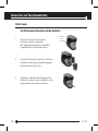
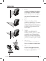
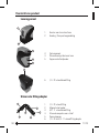
Product Description
Package Contents
1. Laser Unit
2. Universal Mount Adapter
3. Laser Target
4. Carrying Case
5. Batteries (3 x AA)
6. User Manual

6
77-120
1
6
2
3
5
4
1
2
5
4
6
Product Overview
1. Window for Cross Beam Laser
2. Main Power / Transport Lock
3. Keyboard
4. Laser Warning Label
5. Battery Compartment Cover
Laser Unit
6. 1/4 - 20 Threaded Mount
3
Universal Mount Adapter
1. 1/4 - 20 Screw Mount
2. Magnet Mount
3. 5/8 - 11 Threaded Mount
4. Fold Out Legs for Tripod
5. Tightening Knobs
6. 1/4 - 20 to 5/8 - 11 Screw Mount Adapter

7
77-120
Specifications
Leveling Accuracy:
Horizontal / Vertical Accurracy
Working Range:
Working Distance:
with Laser Detector:
Laser Class:
Laser Wavelength:
Operating Time:
Power Voltage:
Power Supply:
IP Rating:
Operating Temperature Range:
Storage Temperature Range:
Weight (without Base and Batteries):
Size:
≤ 3 mm / 10 m (≤ 1/8 in / 30 ft)
≤ 3 mm / 10 m (≤ 1/8 in / 30 ft)
Self-Leveling to ± 4°
≤ 15 m (≤ 50 ft)
≤ 50 m (≤ 165 ft)
Class 1M
635 nm ± 5 nm
12 h
4,5 V
3 x AA Batteries (Alkaline)
IP54
-10° C to +40° C (+14° F to +104° F)
-20° C to +60° C (-4° F to +140° F)
230 g (8 oz)
88 mm × 48 mm × 90 mm
(3 1/2 in × 1 7/8 in × 3 1/2 in)

8
77-120
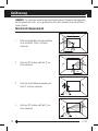
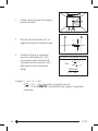
Operating Instructions
1. Turn laser unit to back. Open battery
compartment cover by bending tab out to
unlock.
Lift Out
+
+
+
-
-
-
Battery Installation / Removal
2. Install / Remove batteries. Orient batteries
correctly when placing into laser unit.
3. Close and lock battery compartment
cover. Be sure tab snaps back into locking
feature.

9
77-120
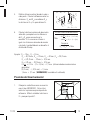
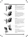
Laser Mode
Laser Unit
OFF / Locked
Unlocked
Pulse Mode
3. Press laser mode key to toggle through
available laser modes - horizontal only,
vertical only, both horizontal and vertical,
self-leveling disabled, laser OFF.
2. Transport lock in unlocked position. Laser
power is ON. Right LED indicator lights green
when laser unit has self-leveled.
4. Mode 4 disables self-leveling feature and
allows both the horizontal and vertical
beams to be positioned in any orientation.
Right LED indicator lights red.
5. Press pulse mode key to toggle between
pulse mode ON and OFF. Left LED lights blue
when pulse mode on. Pulse mode allows use
with a laser detector.
1. Transport lock in locked position. Laser
power is OFF.
6. Laser beam(s) turn off and right LED lights
red to indicate the laser unit is out of
the working range for laser modes 1 - 3.
Reposition laser unit to be more level.

10
77-120
1. 1/4 - 20 screw mount to attach laser unit.
Allows for full 360° placement of the laser
unit.
7. Laser beam(s) will dim when battery power
is low. Replace batteries.
Universal Mount Adapter
360° Placement
3. 5/8 - 11 thread mount available for optional
accessories. Thread mount adapter stored on
unit. 1/4-20 inside thread, 5/8 - 11 outside
thread.
4. Attach to supportive magnetic objects with
the built in magnets.
5. Angles can be set and locked in both axis.
2. Can be used as a miniature tripod using the
fold out legs.
5/8 in
Standard Mount for
Optional Tripod Mounting
Tightening
Knobs

11
77-120
Applications
3. Square:
Using both the vertical and horizontal laser
beams, establish a point where the vertical
and horizontal beams cross. Position the
desired object(s) until they are aligned with
both the vertical and horizontal laser beams
to ensure object(s) are square.
1. Plumb:
Using the vertical laser beam, establish a
vertical reference plane. Position the desired
object(s) until they are aligned with the
vertical reference plane to ensure object(s)
are plumb.
2. Level:
Using the horizontal laser beam, establish
a horizontal reference plane. Position the
desired object(s) until they are aligned with
the horizontal reference plane to ensure
object(s) are level.
4. Pulse Mode:
Setting laser unit to pulse mode allows use
of optional laser detectors.
5. Manual Mode:
Disables self-leveling function and allows
laser unit to project a rigid laser beam in any
orientation.

12
77-120
Calibration
NOTE: The laser unit has been calibrated at the time of manufacturing. Periodically check
the accuracy of the laser unit to ensure that the calibrated specifications are maintained.
1. Place laser unit as shown with laser ON.
Mark point P
1
at cross.
Level Beam Accuracy
2. Rotate laser unit 180° and mark point P
2
at cross.
3. Move laser unit close to wall and mark
point P
3
at cross.
4. Rotate laser unit 180° and mark point P
4
at cross.
P
1
D
1
D
1
2
P
2
P
1
D
1
D
1
2
P
3
P
1
P
2
D
2
P
4
P
1
P
2
P
3
D
2

13
77-120
5. Measure the vertical distance from
the floor to each point. Calculate the
difference between distances D
P1
and D
P3
to get D
3
and distances D
P2
and D
P4
to get
D
4
.
6. Calculate the maximum allowed offset
distance and compare to the difference
of D
3
and D
4
as shown in the equation. If
the sum is not less than or equal to the
calculated maximum offset distance the
unit must be returned to your Stanley
Distributor.
1. Place laser unit as shown with laser
ON. Aim vertical beam to first corner or
reference point. Measure out half of the
distance D
1
and mark point P
1
.
Horizontal Beam Accuracy
P
1
D
1
D
1
2
D
1
2
Example: D
1
= 10 m, D
2
= 0,5 m
D
P1
= 30,75 mm, D
P2
= 29 mm, D
P3
= 30 mm, D
P4
= 29,75 mm
D
3
= (30,75 mm - 30 mm) = 0,75 mm
D
4
= (29 mm - 29,75 mm) = - 0,75 mm
0,3 x (10 m - (2 x 0,5 m) = 2,7 mm (maximum allowed offset distance)
(0,75 mm) - (- 0,75 mm) = 1,5 mm
1,5 mm ≤ 2,7 mm (TRUE, unit is within calibration)
mm
m
P
3
P
1
D
P3
D
P1
(D
P1
- D
P3
) = D
3
P
4
P
2
D
P2
D
P4
(D
P2
- D
P4
) = D
4
Compare:
D
3
- D
4
≤
± Max
Maximum Offset Distance:
Max
in
ft
= 0,0036 x (D
1
ft - (2 x D
2
ft))
mm
m
= 0,3 x (D
1
m - (2 x D
2
m))

14
77-120
P
1
D
2
1
2
P
1
D
1
D
1
2
D
1
2
2. Rotate laser unit to other corner or
reference point.
3. Measure the vertical distances between
P
1
and the horizontal beam from the 2nd
location.
4. Calculate the maximum allowed offset
distance and compare to D
2
. If D
2
is
not less than or equal to the calculated
maximum offset distance the unit must be
returned to your Stanley Distributor.
Example: D
1
= 5 m, D
2
= 1 mm
0,3 x 5 m = 1,5 mm (maximum allowed offset distance)
1 mm ≤ 1,5 mm (TRUE, unit is within calibration)
mm
m
Compare:
D
2
≤
Max
Maximum Offset Distance:
Max
in
ft
= 0,0036 x D
1
ft
mm
m
= 0,3 x D
1
m

15
77-120
Vertical Beam Accuracy
P
1
D
1
P
2
P
3
D
1
2 x D
1
P
4
D
1
P
2
P
3
D
1
2 x D
1
P
1
P
1
D
2
1. Measure the height of a door jamb or
reference point to get distance D
1
. Place
laser unit as shown with laser ON. Aim
vertical beam towards door jamb or
reference point. Mark points P
1
, P
2
, and
P
3
as shown.
2. Move laser unit to opposite side of door
jamb or reference point and align vertical
beam with P
2
and P
3
.
3. Measure the horizontal distances between
P
1
and the vertical beam from the 2nd
location.
4. Calculate the maximum allowed offset
distance and compare to D
2
. If D
2
is
not less than or equal to the calculated
maximum offset distance the unit must be
returned to your Stanley Distributor.
Example: D
1
= 2 m, D
2
= 0,5 mm
0,6 x 2 m = 1,2 mm (maximum allowed offset distance)
0,5 mm ≤ 1,2 mm (TRUE, unit is within calibration)
mm
m
Compare:
D
2
≤
Max
Maximum Offset Distance:
Max
in
ft
= 0,0072 x D
1
ft
mm
m
= 0,6 x D
1
m

16
77-120
Laser unit is not waterproof. DO NOT allow to get wet. Damage to internal circuits may
result.
DO NOT leave laser unit in direct sunlight or expose it to high temperatures. The housing
and some internal parts are made of plastic and may become deformed at high temperatures.
DO NOT store the laser unit in a cold environment. Moisture may form on interior parts
when warming up. This moisture could fog up laser windows and cause corrosion of internal
circuit boards.
When working in dusty locations, some dirt may collect on the laser window. Remove any
moisture or dirt with a soft, dry cloth.
DO NOT use aggressive cleaning agents or solvents.
Store the laser unit in its case when not in use. If storing for extended time, remove batteries
before storage to prevent possible damage to the instrument.
Maintenance and Care

17
77-120
One Year Warranty
Stanley Tools warrants its electronic measuring tools against deficiencies in materials and/or
workmanship for one year from date of purchase.
Deficient products will be repaired or replaced, at Stanley Tools’ option, if sent together with
proof of purchase to:
Stanley UK Sales Limited
Gowerton Road
Brackmills, Northampton NN4 7BW
This Warranty does not cover deficiencies caused by accidental damage, wear and tear, use
other than in accordance with the manufacturer’s instructions or repair or alteration of this
product not authorised by Stanley Tools.
Repair or replacement under this Warranty does not affect the expiry date of the Warranty.
To the extent permitted by law, Stanley Tools shall not be liable under this Warranty for
indirect or consequential loss resulting from deficiencies in this product.
This Warranty may not be varied without the authorisation of Stanley Tools.
This Warranty does not affect the statutory rights of consumer purchasers of this product.
This Warranty shall be governed by and construed in accordance with the laws of England
and Stanley Tools and the purchaser each irrevocably agrees to submit to the exclusive
jurisdiction of the courts of England over any claim or matter arising under or in connection
with this Warranty.
IMPORTANT NOTE: The customer is responsible for the correct use and care of the
instrument. Moreover, the customer is completely responsible for periodically checking the
accuracy of the laser unit, and therefore for the calibration of the instrument.
Calibration and care are not covered by warranty.
Subject to change without notice
Warranty

18
77-120
Lesen Sie vor der Verwendung dieses Produkts aufmerksam die Sicherheitshinweise und die
Bedienungsanleitung. Die für das Instrument verantwortliche Person muss gewährleisten,
dass sämtliche Benutzer die darin enthaltenen Anweisungen verstehen und befolgen.
Heben Sie diese Bedienungsanleitung auf.
WICHTIG: Die folgenden Etiketten auf Ihrem Lasergerät erleichtern Ihnen die Arbeit und
dienen Ihrer Sicherheit. Sie zeigen an, wo Laserlicht ausgestrahlt wird. Wenn Sie die
Nivellierung benutzen, sollten Sie STETS ihre Position KENNEN.
1. Sicherheit
2. Produktbeschreibung
3. Technische Daten
4. Betriebsanleitung
5. Kalibrierung
6. Wartung und Pflege
7. Gewährleistung
Benutzersicherheit
Sicherheit
Inhaltsverzeichnis
EN 60825-1
LASERSTRAHLUNG - NICHT
IN DEN STRAHL SEHEN ODER
DIREKT MIT OPTISCHEN
INSTRUMENTEN BETRACHTEN
LASERPRODUKT DER KLASSE 1M
MAXIMALE LEISTUNG ≤ 1 mW @ 630 - 670 nm
GB
D
F
I
E
PT
NL
DK
SE
FIN
NO
PL
GR
CZ
RU
HU
SK
SI
BG
RO
EE
LV
GB
D
F
I
E
PT
NL
DK
SE
FIN
NO
PL
GR
CZ
RU
HU
SK
SI
BG
RO
EE
LV
TR
GB
D
F
I
E
PT
NL
DK
SE
FIN
NO
PL
GR
CZ
RU
HU
SK
SI
BG
RO
EE
LV
GB ENGLISH
GERMAN
FRENCH
ITALIAN
SPANISH
PORTUGUESE
DUTCH
DANISH
SWEDISH
FINNISH
NORWEGIAN
POLISH
GREEK
CZECH
RUSSIAN
HUNGARIAN
SLOVAKIAN
SLOVENIAN
BULGARIAN
ROMANIAN
ESTONIAN
LATVIAN
LITHUANIAN
TURKISH
CROATIAN
D
F
I
E
PT
NL
DK
SE
FIN
NO
PL
GR
CZ
RU
HU
SK
SI
BG
RO
EE
LV
LT LT LT LT
TR TR TR
HR HR HR HR

19
77-120
Entfernen Sie KEINE Warnetiketten vom Gehäuse. Dieses Instrument darf nur für die in
dieser Anleitung beschriebenen Nivellier- und Layoutaufgaben verwendet werden.
Sorgen Sie STETS dafür, dass alle Personen in der Nähe des Geräts über die Gefahren bei
direktem Blick in das Lasergerät informiert sind.
NICHT in Kombination mit anderen optischen Instrumenten verwenden. Verändern Sie das
Instrument nicht, manipulieren Sie es nicht und verwenden Sie es für keine Anwendungen,
die nicht in dieser Anleitung beschrieben sind.
Blicken Sie NIEMALS mit optischen Hilfsmitteln wie Lupen, Ferngläsern oder Teleskopen
in den Strahl.
NIEMALS in den Laserstrahl starren oder den Laserstrahl direkt auf andere Personen
richten. Achten Sie darauf, das Instrument nicht auf Augenhöhe aufzustellen. Für gewöhnlich
erfolgt der Augenschutz durch natürliche Schutzreaktionen wie Blinzeln.
Richten Sie den Laserstrahl NIEMALS direkt auf andere Personen.
Schalten Sie das Lasergerät IMMER aus, wenn es nicht verwendet wird. Bei dauerhaft
eingeschaltetem Lasergerät erhöht sich das Risiko, dass jemand unabsichtlich in den
Laserstrahl blickt.
Das Lasergerät darf NICHT in hochgradig brennbaren Umgebungen eingesetzt werden, z.
B. in der Nähe von entflammbaren Flüssigkeiten, Gasen oder Staub.
Zerlegen Sie das Lasergerät NIEMALS. Im Innern befinden sich keine Komponenten, die
vom Benutzer gewartet oder repariert werden könnten. Die Zerlegung des Lasers führt zum
Verfall aller Garantien des Produkts. Das Produkt darf auf keine Weise modifiziert werden.
Durch Modifizieren des Lasergeräts entsteht die Gefahr, sich gefährlicher Laserstrahlung
auszusetzen.
Verwenden Sie dieses Instrument NICHT in Bereichen, in denen Explosionsgefahr
gegeben ist.
HINWEIS: Da es sich um einen gebündelten Laserstrahl handelt, ist der Weg des Lasers
unbedingt über eine relativ lange Strecke zu überprüfen, und es sind sämtliche erforderlichen
Maßnahmen zu ergreifen, um zu gewährleisten, dass der Strahl nicht auf Personen treffen
kann.

20
77-120
WARNUNG: Batterien können explodieren oder auslaufen und Verletzungen oder Feuer
verursachen. Folgende Maßnahmen reduzieren dieses Risiko:
Befolgen Sie IMMER sämtliche Anweisungen und Warnhinweise auf der Batterie und ihrer
Verpackung.
Schließen Sie Batterieanschlüsse NIEMALS kurz.
Laden Sie Alkali-Batterien NICHT auf.
Vermischen Sie NICHT alte und neue Batterien. Ersetzen Sie alle gleichzeitig durch neue
Batterien der gleichen Marke und des gleichen Typs.
Vermischen Sie KEINE chemisch unterschiedlichen Batterietypen.
Entsorgen Sie Batterien NICHT durch Verbrennen.
Bewahren Sie Batterien IMMER außerhalb der Reichweite von Kindern auf.
Entfernen Sie IMMER die Batterien, wenn das Gerät über mehrere Monate nicht zum
Einsatz kommt.
HINWEIS: Achten Sie darauf, dass die richtigen, empfohlenen Batterien verwendet werden.
HINWEIS: Achten Sie darauf, dass Batterien richtig ausgerichtet eingelegt werden.
Entsorgen Sie dieses Produkt NICHT im Hausmüll.
Entsorgen Sie Batterien IMMER gemäß den vor
Ort geltenden Bestimmungen.
BITTE UM WIEDERVERWERTUNG gemäß den örtlichen Bestimmungen für die Sammlung
und Entsorgung von Elektro- und Elektronikabfall unter der WEEE-Richtlinie.
Batteriesicherheit
Entsorgung
La page charge ...
La page charge ...
La page charge ...
La page charge ...
La page charge ...
La page charge ...
La page charge ...
La page charge ...
La page charge ...
La page charge ...
La page charge ...
La page charge ...
La page charge ...
La page charge ...
La page charge ...
La page charge ...
La page charge ...
La page charge ...
La page charge ...
La page charge ...
La page charge ...
La page charge ...
La page charge ...
La page charge ...
La page charge ...
La page charge ...
La page charge ...
La page charge ...
La page charge ...
La page charge ...
La page charge ...
La page charge ...
La page charge ...
La page charge ...
La page charge ...
La page charge ...
La page charge ...
La page charge ...
La page charge ...
La page charge ...
La page charge ...
La page charge ...
La page charge ...
La page charge ...
La page charge ...
La page charge ...
La page charge ...
La page charge ...
La page charge ...
La page charge ...
La page charge ...
La page charge ...
La page charge ...
La page charge ...
La page charge ...
La page charge ...
La page charge ...
La page charge ...
La page charge ...
La page charge ...
La page charge ...
La page charge ...
La page charge ...
La page charge ...
La page charge ...
La page charge ...
La page charge ...
La page charge ...
La page charge ...
La page charge ...
La page charge ...
La page charge ...
La page charge ...
La page charge ...
La page charge ...
La page charge ...
La page charge ...
La page charge ...
La page charge ...
La page charge ...
La page charge ...
La page charge ...
La page charge ...
La page charge ...
La page charge ...
La page charge ...
La page charge ...
La page charge ...
La page charge ...
La page charge ...
La page charge ...
La page charge ...
La page charge ...
La page charge ...
La page charge ...
La page charge ...
La page charge ...
La page charge ...
La page charge ...
La page charge ...
La page charge ...
La page charge ...
La page charge ...
La page charge ...
La page charge ...
La page charge ...
La page charge ...
La page charge ...
La page charge ...
La page charge ...
La page charge ...
La page charge ...
La page charge ...
La page charge ...
La page charge ...
La page charge ...
La page charge ...
La page charge ...
La page charge ...
La page charge ...
La page charge ...
La page charge ...
La page charge ...
La page charge ...
La page charge ...
La page charge ...
La page charge ...
La page charge ...
-
 1
1
-
 2
2
-
 3
3
-
 4
4
-
 5
5
-
 6
6
-
 7
7
-
 8
8
-
 9
9
-
 10
10
-
 11
11
-
 12
12
-
 13
13
-
 14
14
-
 15
15
-
 16
16
-
 17
17
-
 18
18
-
 19
19
-
 20
20
-
 21
21
-
 22
22
-
 23
23
-
 24
24
-
 25
25
-
 26
26
-
 27
27
-
 28
28
-
 29
29
-
 30
30
-
 31
31
-
 32
32
-
 33
33
-
 34
34
-
 35
35
-
 36
36
-
 37
37
-
 38
38
-
 39
39
-
 40
40
-
 41
41
-
 42
42
-
 43
43
-
 44
44
-
 45
45
-
 46
46
-
 47
47
-
 48
48
-
 49
49
-
 50
50
-
 51
51
-
 52
52
-
 53
53
-
 54
54
-
 55
55
-
 56
56
-
 57
57
-
 58
58
-
 59
59
-
 60
60
-
 61
61
-
 62
62
-
 63
63
-
 64
64
-
 65
65
-
 66
66
-
 67
67
-
 68
68
-
 69
69
-
 70
70
-
 71
71
-
 72
72
-
 73
73
-
 74
74
-
 75
75
-
 76
76
-
 77
77
-
 78
78
-
 79
79
-
 80
80
-
 81
81
-
 82
82
-
 83
83
-
 84
84
-
 85
85
-
 86
86
-
 87
87
-
 88
88
-
 89
89
-
 90
90
-
 91
91
-
 92
92
-
 93
93
-
 94
94
-
 95
95
-
 96
96
-
 97
97
-
 98
98
-
 99
99
-
 100
100
-
 101
101
-
 102
102
-
 103
103
-
 104
104
-
 105
105
-
 106
106
-
 107
107
-
 108
108
-
 109
109
-
 110
110
-
 111
111
-
 112
112
-
 113
113
-
 114
114
-
 115
115
-
 116
116
-
 117
117
-
 118
118
-
 119
119
-
 120
120
-
 121
121
-
 122
122
-
 123
123
-
 124
124
-
 125
125
-
 126
126
-
 127
127
-
 128
128
-
 129
129
-
 130
130
-
 131
131
-
 132
132
-
 133
133
-
 134
134
-
 135
135
-
 136
136
-
 137
137
-
 138
138
-
 139
139
-
 140
140
-
 141
141
-
 142
142
-
 143
143
-
 144
144
-
 145
145
-
 146
146
-
 147
147
-
 148
148


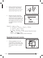
Stanley CL2i Manuel utilisateur
- Catégorie
- Niveaux laser
- Taper
- Manuel utilisateur
dans d''autres langues
- italiano: Stanley CL2i Manuale utente
- English: Stanley CL2i User manual
- español: Stanley CL2i Manual de usuario
- Deutsch: Stanley CL2i Benutzerhandbuch
- Nederlands: Stanley CL2i Handleiding
- português: Stanley CL2i Manual do usuário
- dansk: Stanley CL2i Brugermanual
- svenska: Stanley CL2i Användarmanual
Documents connexes
-
Stanley CL90i Le manuel du propriétaire
-
Stanley MultiLine 77-122 Le manuel du propriétaire
-
-
-
Stanley CL2XTi Le manuel du propriétaire
-
-
-
-
Stanley SML 77-322 Le manuel du propriétaire
-