
IMPORTANT DOCUMENTS ENCLOSED
CAUTION:
To reduce the risk of injury due to hot water
burns, make sure the enclosed labels are
applied where specified on the label.
DOCUMENTOS IMPORTANTES INCLUIDOS
AVISO:
Para reducir el riesgo de lesión por
quemaduras de agua caliente, asegúrese que
las etiquetas incluidas se han aplicado donde
se ha especificado en la etiqueta.
DOCUMENTS IMPORTANTS À L’INTÉRIEUR
MISE EN GARDE :
Pour réduire le risque d’ébouillantage, veuillez
apposer les étiquettes fournies aux endroits
indiqués sur celles-ci.
51975
51975

4/2/09 51975 Rev D
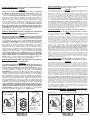
NOTICE TO INSTALLER: Place this label on the water heater next
to the temperature adjustment knob.
WARNING:
These series of tub/shower valves do not adjust automatically
for changes in temperature at the hot water heater or inlet. If the
temperature setting of the hot water heater or inlet is changed, the setting
on these valves must be adjusted manually! Failure to re-adjust the valve
may result in hot water burns or extreme cold resulting from variations in
line pressure (such as when a dishwasher or washing machine is in use
while you are taking a shower). After installation, verify that the rotational
limit stop (13/14/17 series) or temperature knob (17T series) on the valve
is set so that changes in line pressure or temperature do not result in
uncomfortable water temperature changes. If the temperature setting of
the hot water heater or inlet is changed after installation of the valve,
the setting of the rotational limit stop or temperature knob also must
be changed! Consult the installation instruction sheet for instructions on
how to make this setting, or call us at 1-800-345-DELTA.
AVISO AL INSTALADOR: Coloque esta etiqueta en el calentador
de agua al lado de la perilla para el ajuste de temperatura.
AVISO:
Esta serie de válvulas para bañeras/regaderas no se ajustan automáti-
camente a los cambios de temperatura en el calentador de agua o en
el agua de entrada. Si el ajuste de la temperatura del calentador de agua
o la temperatura del agua que entra cambia ¡El ajuste de estas válvulas
se debe hacer manualmente! El no reajustar la válvula puede resultar en
quemaduras por agua caliente o temperaturas de agua extremadamente
frías resultando en variaciones de presión y temperatura (como cuando el
fregador de platos o la lavadora están funcionando mientras que se baña).
Después de la instalación, verifique que el control o tope del límite rotacional
(series 13/14/17) o la perilla del control de temperatura (series 17T ) en la
válvula está ajustada para que los cambios de presión y de temperatura
en la línea no resulten en cambios incómodos de temperatura del agua. Si
el ajuste de la temperatura del calentador de agua o de la entrada de
agua se cambia después de la instalación de la válvula, el ajuste del
tope del límite rotacional o la perilla de ajuste ¡también se debe cam-
biar! Consulte con su hoja de instrucciones de instalación para saber como
se ajusta o cambia el ajuste, o llámenos al 1-800-345-DELTA.
AVIS À L’INSTALLATEUR: Fixez cette étiquette sur le chauffe-eau
près du bouton de réglage de température.
ATTENTION :
La soupape de robinet de baignoire ou de douche de cette série ne se
règle pas automatiquement en fonction des changements de température
de l’eau chaude au chauffe-eau ou de l’eau d’alimentation. En cas de
modification du réglage de température du chauffe-eau ou de la température
de l’eau d’alimentation, le réglage de cette soupape doit être modifié
manuellement! Si le réglage de la soupape n’est pas modifié, le robinet pourra
permettre l’écoulement d’eau très chaude susceptible de causer l’ébouillantage
ou d’eau très froide, sous l’effet des variations de pression et de température
dans la tuyauterie d’alimentation (lorsque la douche est utilisée en même temps
que le lave-vaisselle ou la machine à laver, par exemple). Après l’installation,
assurez-vous que la butée de température maximale (séries 13/14/17) ou le
bouton de température (séries 17T) sur la soupape est réglé de manière que
les fluctuations de pression et de température dans la tuyauterie d’alimentation
n’entraînent pas de changements de température de l’eau inconfortables. En
cas de modification du réglage de température du chauffe-eau ou de la
température de l’eau d’alimentation après l’installation de la soupape, le
réglage de la butée de température maximale ou du bouton de température
doit être modifié! Pour régler le bouton de température, consultez la feuille
d’instructions d’installation ou appelez-nous au 1-800-345-DELTA.
4/2/09 51975 Rev D
BY/POR/PAR _______________ COMPANY/COMPANIA/COMPAGNIE ________________
DATE/FECHA/LE ___________ PHONE/TELÉFONO/TELÉPHONE ____________________
NOTICE TO INSTALLER: Place this label close to the valve where the owner
will see it, such as inside the door of a cabinet or vanity.
WARNING:
Water temperature changes due to seasonal or other inlet variations, such as changing the setting
on the hot water heater may require adjustment of the rotational limit stop (13/14/17 Series) or
temperature knob (17T Series) on your tub/shower valve to ensure a safe maximum temperature.
These valve series do not automatically adjust for inlet temperature changes. If changes occur and
you are not sure how to make the necessary rotational limit stop or temperature knob adjustments,
please consult the installation instruction sheet provided with this valve or call 1-800-345-DELTA.
These valve series are designed to minimize the effects of outlet water temperature changes
due to inlet pressure changes, commonly caused by dishwashers, washing machines, toilets and
the like. They may not provide protection from hot water burns when there is a failure of
other temperature controlling devices elsewhere in the plumbing system. After making the
necessary adjustments please fill in the information below. This valve/system has been set by the
person listed below to ensure a safe maximum temperature. Any change in the setting may raise
the discharge temperature above the limit considered safe and could lead to hot water burns. If
this label has not been completed, you should verify that the rotational limit stop or temperature
knob has been properly adjusted to suit your individual installation. The installation instruction sheet
supplied with the valve provides information on how to make this setting.
AVISO AL INSTALADOR: Coloque esta etiqueta cerca de la válvula donde el
propietario la pueda ver, tal como dentro de la puerta del gabinete o el tocador.
AVISO:
Los cambios de temperatura del agua por variaciones estacionales u otras variaciones en el agua
de entrada, como el cambio por el ajuste en el calentador de agua, puede requerir el ajuste del
tope del límite rotacional (Series 13/14/17) o ajuste de la perilla para el control de la temperatura
(Series 17T) de la válvula de su unidad bañera/regadera para asegurar una temperatura máxima
segura. Esta serie de válvulas no se ajusta automáticamente para los cambios de temperatura del
agua de entrada. Si cambios ocurren y usted no está seguro como hacer los ajustes necesarios
con la perilla para controlar la temperatura, por favor consulte la hoja de instrucciones de
instalación proporcionada con esta válvula o llámenos al 1-800-345-DELTA. Las válvulas de esta
serie están diseñadas para minimizar los efectos por cambios de temperatura en el agua de
entrada por cambios en la presión del agua, comúnmente causados por el uso simultáneo de
fregadoras de platos, lavadoras, inodoros y aparatos similares. Estas pueden no proporcionar
protección de quemaduras por el agua caliente cuando hay una falla de otros mecanismos
que controlan la temperatura del agua en otro sitio del sistema de plomería. Después de
hacer los ajustes necesarios, por favor escriba la información suministrada a continuación. Esta
válvula/sistema ha sido ajustada por la persona indicada a continuación para ayudar a asegurar
una temperatura máxima segura. Cualquier cambio al ajuste puede aumentar la temperatura del
agua de descarga sobre el límite considerado seguro y puede resultar en quemaduras por agua
caliente. Si esta etiqueta no se ha llenado, debe verificar si el control o tope del límite rotacional o
la perilla que controla la temperatura han sido correctamente ajustadas al gusto de su instalación
individual. La hoja de instrucciones de instalación proporcionada con las válvulas le suministra
información sobre como hacer este ajuste.
AVIS À L’INSTALLATEUR: Fixez cette étiquette près du robinet, à la vue du
propriétaire, à l’intérieur de la porte du meuble ou de la coiffeuse, par exemple.
ATTENTION :
Les modifications de la température de l’eau attribuables au changement de saison ou à d’autres
facteurs, comme la modification du réglage du chauffe-eau, peuvent nécessiter un réglage de la
butée de température maximale (séries 13/14/17) ou du bouton de température (séries 17T) de la
soupape de votre robinet pour baignoire et de douche. La soupape de robinet de ces séries ne se
règle pas automatiquement en fonction des changements de température de l’eau chaude de l’eau
d’alimentation. En cas de modification de la température de l’eau d’alimentation, si vous ne savez
pas comment régler la butée de température maximale ou le bouton de température, veuillez con-
sulter le feuillet d’instructions d’installation fourni avec la soupape ou appeler au 1-800-345-DELTA.
La soupape de cette série est conçue pour limiter la variation de la température de l’eau pouvant
résulter des fluctuations de température et de pression dans la tuyauterie d’alimentation. Ces fluc-
tuations sont habituellement causées par une utilisation simultanée du lave-vaisselle, de la machine
à laver, d’un cabinet d’aisances ou d’un autre appareil qui consomme de l’eau. La soupape peut
ne pas protéger l’utilisateur contre l’ébouillantage en cas de défectuosité d’un autre dis-
positif de régulation de la température de l’eau situé ailleurs dans la tuyauterie. Après avoir
effectué les réglages nécessaires, veuillez inscrire l’information requise ci-dessous. Cet appareil
de robinetterie a été réglé par la personne dont le nom figure ci-dessous pour que la température
maximale de l’eau soit sans danger. Toute modification du réglage peut occasionner une élévation
de la température de l’eau à la sortie du robinet et l’eau qui s’écoulera pourra être suffisamment
chaude pour causer l’ébouillantage. Si la présente étiquette n’a pas été remplie, assurez-vous
que la butée de température maximale ou le bouton de température a bien été réglé en fonction
des caractéristiques de votre installation. La marche à suivre pour faire le réglage figure dans les
instructions d’installation fournies avec la soupape.
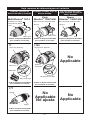
TO BE FILLED OUT BY THE INSTALLER / PARA SER LLENADO POR EL INSTALADOR /
A REMPLIR PAR L’INSTALLATEUR:
Rotational Limit Stop is
located behind the disc.
13 / 14 Series
17 Series
Hotter
Más
Caliente
Plus
Chaud
1st Position
Primera Posición
1ère Position
17T Series
Hotter
Más
Caliente
Plus
Chaud
Colder
Más
Fría
Plus
Froid
13 / 14 Series
17 Series
Hotter
Más
Caliente
Plus
Chaud
Hotter
Más
Caliente
Plus
Chaud
Colder
Más
Fría
Plus
Froid
1st Position
Primera Posición
1ère Position
Temperature Knob
Pomo para el ajuste
de temperatura
Bouton de Température
17T Series
Temperature Knob
Pomo para el ajuste
de temperatura
Bouton de Température
Rotational Limit Stop is
located behind the disc.

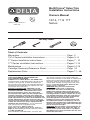
MultiChoice
®
Valve Trim
Installation Instructions
Owners Manual
13/14, 17 & 17T
Series
Write purchased model number here.
ASME A112.18.1 / CSA B125.1
ASSE 1016
®
®
U
P
C
Table of Contents:
Warranties .......................................................................... Page 2
13/14 Series Installation Instructions .................................. Pages 3 - 6
17 Series Installation Instructions ....................................... Pages 7 - 10
17T Series Installation Instructions ......................................Pages 11-14
Maintenance ....................................................................... Pages 14-15
Cartridge Summary Reference Sheet ................................. Page 16
Replacement Parts ............................................................. Pages 17 - 46
1
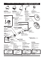
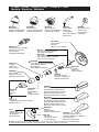
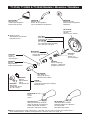
You May Need
T
E
F
L
O
N
4/2/09
51975 Rev. D
THIS VALVE MEETS OR EXCEEDS THE
FOLLOWING STANDARDS:
ASME A112.18.1/CSA B125.1 and ASSE 1016.
CAUTION: This system/device must be set by the
installer to ensure safe, maximum temperature.
Any change in the setting may raise the discharge
temperature above the limit considered safe and
may lead to hot water burns.
NOTICE TO INSTALLER: CAUTION!–As the
installer of this valve, it is your responsibility
to properly INSTALL and ADJUST this valve
per the instructions given. This valve does
not automatically adjust for inlet temperature
changes, therefore, someone must make the
necessary Rotational Limit Stop or temperature
knob adjustments at the time of installation and
further adjustments may be necessary due to
seasonal water temperature change. YOU MUST
inform the owner/user of this requirement by
following the instructions. If you or the owner/
user are unsure how to properly make
these adjustments, please refer to
page 5 (13 / 14 series), page 10 (17 series) or
page 14 (17T series) and if still uncertain, call us
at 1-800-345-DELTA.
After installation and adjustment, you must affix
your name, company name and the date you
adjusted the Rotational Limit Stop or temperature
knob to the caution label provided and apply or
attach the label to the back side of the closest
cabinet door and the warning label to the water
heater. Leave this Instruction Sheet for the
owner’s/user’s reference.
WARNING: This pressure balanced or
thermostatic bath valve is designed
to minimize the effects of outlet water
temperature changes due to inlet pressure
changes, commonly caused by dishwashers,
washing machines, toilets and the like. It may
not provide protection from hot water burns
when there is a failure of other temperature
controlling devices elsewhere in the
plumbing system, if the rotational limit stop
or temperature knob is not properly set or if
the hot water temperature is changed after the
settings are made or if the water inlet changes
due to seasonal changes.
WARNING: Do not install a shut-off device on
either outlet of this valve. When this type of
device shuts off the water flow, it can defeat
the ability of the valve to balance the hot and
cold water pressures.

All parts and finishes of the Delta® faucet are
warranted to the original consumer purchaser to
be free from defects in material & workmanship
for as long as the original consumer purchaser
owns their home. Delta Faucet Company
recommends using a professional plumber for all
installation & repair.
Delta will replace, FREE OF CHARGE, during
the warranty period, any part or finish that proves
defective in material and/or workmanship under
normal installation, use & service. Replacement
parts may be obtained by calling 1-800-345-
DELTA (in the U.S. and Canada) or by writing to:
In the United States:
Delta Faucet Company
Product Service
55 E. 111th Street
Indianapolis, IN 46280
In Canada:
Masco Canada
Technical Service Centre
420 Burbrook Place
London, ON N6A 4L6
This warranty is extensive in that it covers
replacement of all defective parts and even
finish, but these are the only two things that
are covered. LABOR CHARGES AND/OR
DAMAGE INCURRED IN INSTALLATION,
Lifetime Faucet and Finish Limited Warranty
REPAIR, OR REPLACEMENT AS WELL AS ANY
OTHER KIND OF LOSS OR DAMAGES ARE
EXCLUDED. Proof of purchase (original sales
receipt) from the original consumer purchaser
must be made available to Delta for all warranty
claims. THIS IS THE EXCLUSIVE WARRANTY
BY DELTA FAUCET COMPANY, WHICH DOES
NOT MAKE ANY OTHER WARRANTY OF ANY
KIND, INCLUDING THE IMPLIED WARRANTY
OF MERCHANTABILITY.
This warranty excludes all industrial, commercial
& business usage, whose purchasers are
hereby extended a five year limited warranty
from the date of purchase, with all other terms of
this warranty applying except the duration of the
warranty. This warranty is applicable to Delta®
faucets manufactured after January 1, 1995.
Some states/provinces do not allow the exclusion
or limitation of incidental or consequential
damages, so the above limitation or exclusion
may not apply to you. Any damage to this faucet
as a result of misuse, abuse, or neglect, or any
use of other than genuine Delta® replacement
parts WILL VOID THE WARRANTY.
This warranty gives you specific legal rights, and
you may also have other rights which vary from
state/province to state/province. It applies only for
Delta® faucets installed in the United States of
America, Canada, and Mexico.
© 2009 Masco Corporation of Indiana
All parts of the Delta HDF faucet are warranted to
the original consumer purchaser to be free
from defects in material and workmanship for a
period of five (5) years. This warranty is made
to the original consumer purchaser and shall be
effective from date of purchase as shown on
purchaser’s receipt.
Delta will replace, FREE OF CHARGE, during
the warranty period, any part which proves
defective in material and/or workmanship
under normal installation, use and service.
Replacement parts can be obtained from your
local dealer or distributor listed in the tele-
phone directory or by returning the part along
with the purchaser’s receipt to our factory,
TRANSPORTATION CHARGES PREPAID,
at the address listed. THIS WARRANTY IS THE
ONLY EXPRESS WARRANTY MADE BY DELTA.
ANY CLAIMS MADE UNDER THIS WARRANTY
MUST BE MADE DURING THE FIVE YEAR
PERIOD REFERRED TO ABOVE. ANY IMPLIED
WARRANTIES, INCLUDING THE IMPLIED
WARRANTY OF MERCHANTABILITY OR
FITNESS FOR A PARTICULAR PURPOSE, ARE
LIMITED IN DURATION TO THE DURATION OF
THIS WARRANTY. LABOR CHARGES AND/OR
DAMAGE INCURRED IN INSTALLATION,
REPAIR OR REPLACEMENT AS WELL AS
INCIDENTAL AND CONSEQUENTIAL
DAMAGES CONNECTED THEREWITH ARE
EXCLUDED AND WILL NOT BE PAID BY DELTA.
Some states do not allow limitations on how long
an implied warranty lasts, or the exclusion or
limitation of incidental or consequential damages,
so the above limitations or exclusions may not
apply to you.
This warranty gives you specific legal rights, and
you may also have other rights which vary from
state to state.
This warranty is void for any damage to this faucet
due to misuse, abuse, neglect, accident, improper
installation, any use violative of instructions
furnished by us or any use of replacement parts
other than genuine Delta parts.
Delta HDF Limited Warranty
© 2009 Masco Corporation of Indiana
2

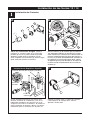
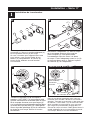
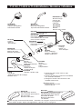
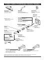
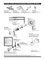
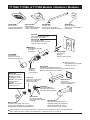
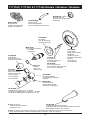
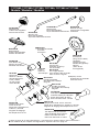
13 / 14 Series Installation
1
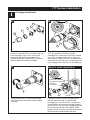
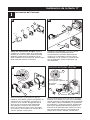
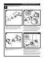
Cartridge Installation
A.
C.
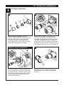
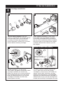
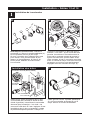
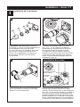
Turn off water supplies. Remove
cover (1), bonnet nut (2) and test cap (3)
from the body. If this is not a thin wall
mounting, the entire plasterguard (4)
may be removed. If screen (5) is in place,
remove before installing cartridge.
For back to back or reverse installations
(hot on right and cold on left) insert the
cartridge with the “hot side” on the right.
If you are not making a reverse or back
to back installation skip this step and
continue with step 1C.
Slide bonnet nut (1) over the cartridge
and thread onto the body. Hand tighten
securely.
B.
Rotate the cartridge (1) so the words
“hot side” (2) appear on the left. Insert
cartridge into valve body as shown. Make
sure the cartridge tubes and O-rings (3)
are properly seated in holes at the base of
the body. Ensure the keys on the body are
fully engaged with the slots in the body (4).
Back to back Installation
Normal Installation (changes not required)
Reverse
Installation
Cold
Hot
1
2
3
1
4
4
2
3
1
3
5
4

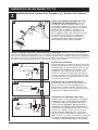
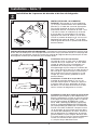
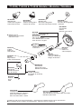
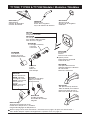
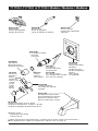
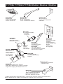
13 / 14 Series Installation
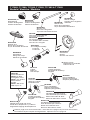
2
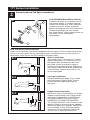
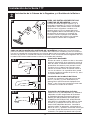
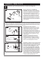
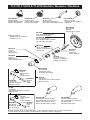
Showerhead and Tub Spout Installation
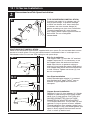
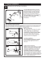
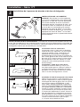
FOR SHOWERHEAD INSTALLATION:
Connect top outlet (1) to shower arm (2)
with proper fittings. To prevent damage
to finish on shower arm, insert wall end
of shower arm into shower flange (3)
before screwing arm into riser connection.
Thread showerhead (4) onto shower
arm. Apply Teflon
®
tape to pipe threads on
both ends. Do not overtighten
showerhead.
A.
3
2
1
Slip-On Installation
The copper tube (1) must be 1/2” nominal
copper. Important: If it is necessary to cut
the copper tube, the end must be cham-
fered free of burrs to prevent cutting or
nicking O-ring inside the spout. Slide spout
over copper tube flush with the finished tub
or wall surface. Tighten set screw (2), but
do not overtighten.
4
1
4
FOR TUB SPOUT INSTALLATION:
Refer to the installation instructions supplied with your spout. Do not connect deck mount
spouts to in-wall valves. Do not use hand showers connected in lieu of a tub spout to a
tub/shower valve. Do not use PEX tubing for tub spout drop.
B-1
B-2
B-3
Iron Pipe Installation
Install threaded pipe nipple (1) to extend
past finished wall. Apply Teflon
®
tape to
threads on pipe nipple and screw on
tub spout.
Copper Sweat Installation
Remove O-ring (1) from adapter (2). Solder
adapter to tube taking care to keep solder
away from O-ring groove. CAUTION: NO
SOLDER PERMITTED ON OUTSIDE
DIAMETER OF ADAPTER ADJACENT
TO O-RING GROOVE. Cut off tube (3) and
replace O-ring on groove of brass adapter.
Thread tub/spout onto adapter, taking care
not to damage O-ring, and hand tighten until
spout is firmly against finished wall and all
slack is taken up behind wall.
2
1
1
2
3

13 / 14 Series Installation
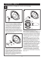
5
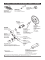
13 / 14 Series Installation
3
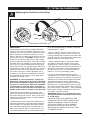
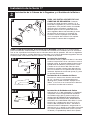
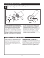
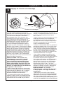
Adjusting the Rotational Limit Stop
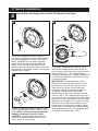
IMPORTANT:
The Rotational Limit Stop is used to limit the
amount of hot water available such that, if set
properly, the user will not be scalded if the han-
dle accidentally is rotated all the way to “hot”
when a person is showering or filling a tub. The
first position allows the LEAST amount of hot
water to mix with the cold water in the system.
In the first position the water will be the coldest
possible when the handle is turned all the way
to hot. As you move the Rotational Limit Stop
counterclockwise, you progressively add more
and more hot water in the mix. The last position
to the left will result in the greatest amount of
hot water to the mix, and the greatest risk of
scald injury if someone accidentally turns the
valve handle all the way to the hot side while
showering or filling a tub.
WARNING: In some instances, setting the
Rotational Limit Stop in the hottest position
(full counterclockwise) could result in scald
injury. It is necessary to adjust the Rotation-
al Limit Stop so that the water coming out
of the valve will not scald the user when the
handle of the valve is rotated to the hot side.
• According to the majority of industry stan-
dards, the maximum allowable temperature of
the water exiting the valve is 120°F (Your local
plumbing codes may require a water tempera-
ture less than 120°F).
• The Rotational Limit Stop may need to be re-
adjusted seasonally if the inlet water tempera-
ture changes. For example, during the winter,
the cold water temperature is colder than it is
during the summer which could result in vary-
ing outlet temperatures. A water temperature
for a comfortable bath or shower is typically
between 90°F - 110°F.
• Run the water so that the cold water is as
cold as it will get and hot water is as hot as
it will get. Place the handle on the stem (see
page 6, step 4D) and rotate the handle coun-
terclockwise until the handle stops.
• Place a thermometer in a plastic tumbler
and hold in the water stream. If the water
temperature is above 120°F, the Rotational
Limit Stop must be repositioned clockwise to
decrease valve outlet water temperature to
be less than 120°F or to meet the require-
ments of your local plumbing codes.
• To adjust the temperature of the water
coming out of the valve, pull the disc back to
a position where it is possible to remove the
Rotational Limit Stop and readjust the teeth
engagement position to the desired tem-
perature. Clockwise will decrease the outlet
temperature, counterclockwise will increase
the outlet temperature. Temperature change
per tooth (notch) could be 4° - 16°F based on
inlet water conditions. Repeat as necessary.
Push disc until fully seated.
WARNING: Failure to re-install Disc after
setting Rotational Limit Stop could result
in scald injury.
• MAKE SURE COLD WATER FLOWS
FROM THE VALVE FIRST. MAKE SURE
WATER FLOWING FROM THE VALVE
AT THE HOTTEST FLOW POSSIBLE
DOES NOT EXCEED 120°F OR THE
MAXIMUM ALLOWED BY YOUR LOCAL
PLUMBING CODE.
1st Position
Hotter
Rotational Limit Stop
Stem
Disc

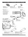
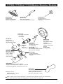
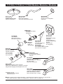
13 / 14 Series Installation
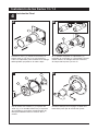
4
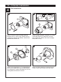
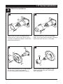
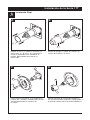
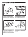
Trim Installation
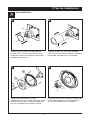
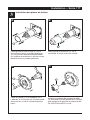
C.
D.
A.
B.
Slide O-ring (1) over cartridge and the
bonnet nut (2). The O-ring, which acts as
a spacer to steady the sleeve, should rest
behind the bonnet nut.
If your model requires a spacer (1), insert
it into the sleeve (2) and push it to the
front. Slide the sleeve over the cartridge,
body and O-ring.
Secure the escutcheon (1) and backplate
(2) (if your model has one) to the bracket
(3) using the 2 screws provided (4). Do not
overtighten escutcheon screws.
Using an Allen wrench to secure the set
screw, install the handle onto the stem.
1
2
1
2
1
1
2
3
4
6

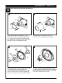
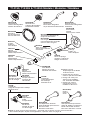
1
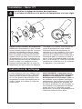
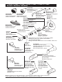
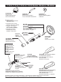
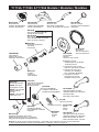
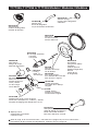
Cartridge Installation
A.
17 Series Installation
C.
Turn off water supplies. Remove
cover (1), bonnet nut (2) and test cap (3)
from the body. If this is not a thin wall
mounting, the entire plasterguard (4)
may be removed. If screen (5) is in place,
remove before installing cartridge.
B.
Rotate cartridge (1) so the words
“HOT SIDE” (2) appear on the left. Insert
cartridge assembly into valve body.
Make sure the key (3) on the cartridge is
fully engaged with the slot in the brass
body (4). Slide bonnet nut (5) over the
cartridge and thread onto the body.
Hand tighten securely.
1
2
3
1
2
1
3
4
7
5
2
3
Insert adapter assembly (1) into valve
body. Make sure the adapter assembly
is correctly positioned and is pressed all
the way down inside body. Secure adapter
with the screw (2) provided in the adapter
assembly. Remove the retainer (3) from
the adapter.
For back to back or reverse installations
(hot on right and cold on left): Rotate
cartridge (1) so the words “HOT SIDE” (2)
appear on the right. Install the cartridge
making sure that the key is fully engaged
with the slot in the brass body (See step C).
Slide bonnet nut (3) over the cartridge and
thread onto the body. Hand tighten securely.
Back to back Installation
Reverse
Installation
Cold
Hot
1
3
Normal Installation
(changes not required)
2
5
4

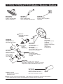
17 Series Installation
8
2
Showerhead and Tub Spout Installation
FOR SHOWERHEAD INSTALLATION:
Connect top outlet (1) to shower arm (2)
with proper fittings. To prevent damage
to finish on shower arm, insert wall end
of shower arm into shower flange (3)
before screwing arm into riser connection.
Thread showerhead (4) onto shower
arm. Apply Teflon
®
tape to pipe threads on
both ends. Do not overtighten
showerhead.
A.
3
2
1
Slip-On Installation
The copper tube (1) must be 1/2” nominal
copper. Important: If it is necessary to
cut the copper tube, the end must be
chamfered free of burrs to prevent cutting
or nicking O-ring inside the spout. Slide
spout over copper tube flush with the
finished tub or wall surface. Tighten set
screw (2), but do not overtighten.
4
1
FOR TUB SPOUT INSTALLATION:
Refer to the installation instructions supplied with your spout. Do not connect deck mount
spouts to in-wall valves. Do not use hand showers connected in lieu of a tub spout to a
tub/shower valve. Do not use PEX tubing for tub spout drop.
B-1
B-2
B-3
Iron Pipe Installation
Install threaded pipe nipple (1) to extend
past finished wall. Apply Teflon
®
tape to
threads on pipe nipple and screw on
tub spout.
Copper Sweat Installation
Remove O-ring (1) from adapter (2). Solder
adapter to tube taking care to keep solder
away from O-ring groove. CAUTION: NO
SOLDER PERMITTED ON OUTSIDE
DIAMETER OF ADAPTER ADJACENT
TO O-RING GROOVE. Cut off tube (3) and
replace O-ring on groove of brass adapter.
Thread tub/spout onto adapter, taking care
not to damage O-ring, and hand tighten until
spout is firmly against finished wall and all
slack is taken up behind wall.
2
1
1
2
3

C.
D.
A.
B.
Slide O-ring (1) over cartridge and the
bonnet nut (2). The O-ring, which acts as
a spacer to steady the sleeve, should rest
behind the bonnet nut.
Slide the sleeve (1) over the cartridge,
body and O-ring. Ensure sleeve is properly
positioned over the front of cartridge.
Secure the escutcheon (1) and
backplate (2) (if your model has one) to the
bracket (3) with the 2 screws provided (4).
Do not overtighten escutcheon screws.
Install volume control handle (1) with lever
to the right, then turn to the on position.
DO NOT SECURE WITH SCREW.
17 Series Installation
3
Trim Installation
1
2
1
1
2
3
4
1
9

4
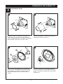
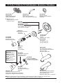
Installation and Adjustment of the Rotational Limit Stop
C.
A.
B.
Place the temperature control knob (1)
on volume handle and rotate to the mixed
position (if required). DO NOT SECURE
WITH SCREW. Turn on water supplies;
let the water run until both hot and cold
water is as hot/cold as possible. Place
thermometer in a plastic tumbler, and hold
the tumbler in the water stream. Record the
temperature reading.
If the water temperature is above 120°F,
remove the temperature control knob (1)
and rotate the limit stop (2) clockwise one
tooth for every 4°F - 6°F (approximate)
change in temperature. If water temperature
is cooler than desired, rotate the limit stop
counterclockwise.
IMPORTANT: The first position of the
Rotational Limit Stop (the Limiter) is that
position that restricts the rotation of the
stem the most and is at the maximum
clockwise setting. According to industry
standards, the maximum allowable
temperature of the water exiting from the
valve is 120
o
F. This temperature may vary
in your local area. The Rotational Limit Stop
may need to be readjusted if the inlet water
temperature changes. For instance, during
the winter, the cold water temperature is
colder than it is during the summer which
could result in varying outlet temperatures.
Typical temperature for a comfortable bath
or shower is between 90
o
–110
o
F.
Secure temperature control knob (1) with
screw (2) and snap control cover (3) onto
knob. NOTE: Secure screw until handle
wobble is reduced, DO NOT FULLY
TIGHTEN. Overtightening will result in
difficulty to operate temperature control
knob. Screw is self locking.
17 Series Installation
1
1
2
2
1
3
10
Hotter
Colder

B.
1
4
4
2
3
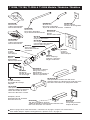
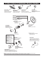
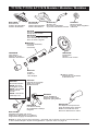
17T Series Installation
1
Cartridge Installation
A.
Turn off water supplies. Remove
cover (1), bonnet nut (2) and test cap (3)
from the body. If this is not a thin wall
mounting, the entire plasterguard (4)
may be removed. If screen (5) is in place,
remove before installing cartridge.
1
2
3
11
4
Rotate the cartridge (1) so the word
“UP” (2) appears on the top. Insert
cartridge into valve body as shown. Make
sure the cartridge tubes and O-rings (3)
are properly seated in holes at the base of
the body. Ensure the keys on the body are
fully engaged with the slots in the body (4).
For back to back or reverse installations
(hot on right and cold on left): Rotate
cartridge (1) so the word “UP” (2) appears
on the bottom. Install the cartridge making
sure that the keys are fully engaged with the
slot in the brass body (see step B). Slide
bonnet nut (3) over the cartridge and thread
onto the body. Hand tighten securely.
Back to back Installation
Normal Installation
(changes not required)
Reverse
Installation
Cold
Hot
1
3
2
C.
Slide bonnet nut (1) over the cartridge
and thread onto the body. Hand tighten
securely.
1
5

17T Series Installation
12
2
3
2
1
4
FOR SHOWERHEAD INSTALLATION:
Connect top outlet (1) to shower arm (2)
with proper fittings. To prevent damage
to finish on shower arm, insert wall end
of shower arm into shower flange (3)
before screwing arm into riser connection.
Thread showerhead (4) onto shower
arm. Apply Teflon
®
tape to pipe threads on
both ends. Do not overtighten
showerhead.
Slip-On Installation
The copper tube (1) must be 1/2” nominal
copper. Important: If it is necessary to cut
the copper tube, the end must be cham-
fered free of burrs to prevent cutting or
nicking O-ring inside the spout. Slide spout
over copper tube flush with the finished tub
or wall surface. Tighten set screw (2), but
do not overtighten.
1
FOR TUB SPOUT INSTALLATION:
Refer to the installation instructions supplied with your spout. Do not connect deck mount
spouts to in-wall valves. Do not use hand showers connected in lieu of a tub spout to a
tub/shower valve. Do not use PEX tubing for tub spout drop.
B-1
B-2
B-3
Iron Pipe Installation
Install threaded pipe nipple (1) to extend
past finished wall. Apply Teflon
®
tape to
threads on pipe nipple and screw on
tub spout.
Copper Sweat Installation
Remove O-ring (1) from adapter (2). Solder
adapter to tube taking care to keep solder
away from O-ring groove. CAUTION: NO
SOLDER PERMITTED ON OUTSIDE
DIAMETER OF ADAPTER ADJACENT
TO O-RING GROOVE. Cut off tube (3) and
replace O-ring on groove of brass adapter.
Thread tub/spout onto adapter, taking care
not to damage O-ring, and hand tighten
until spout is firmly against finished wall
and all slack is taken up behind wall.
2
1
1
2
3
Showerhead and Tub Spout Installation
A.

C.
D.
A.
B.
Slide O-ring (1) over cartridge and the
bonnet nut (2). The O-ring, which acts as
a spacer to steady the sleeve, should rest
behind the bonnet nut.
Slide the sleeve (1) over the cartridge,
body and O-ring. Ensure sleeve is properly
positioned over the front of cartridge.
Secure the escutcheon (1) to the bracket
(2) with the 2 screws provided (3).
Do not overtighten escutcheon screws.
Install volume control handle (1) with
lever to the right. DO NOT SECURE
WITH SCREW.
3
Valve Trim Installation
1
2
1
1
2
1
3
17T Series Installation
13

Cleaning and Care
4
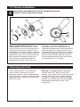
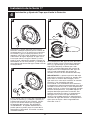
Installation and Adjustment of the Temperature Knob
Failure to do so may cause injury.
17T Series Installation
14
Adjust temperature limit stop! Turn on
water supplies; let the water run at both
full hot and full cold to ensure the water is
running as hot/cold as possible. Place a
thermometer in a plastic tumbler, and hold
the tumbler in the water stream. Place the
temperature knob (1) onto the splines (2),
then rotate the temperature knob until
you achieve your maximum desired
temperature from the outlet (not more
than 120° or the lower temperature
mandated by your local plumbing code).
Remove the temperature knob and replace
onto the splines (2), making sure that the
temperature knob limit stop (3) hits against
the volume handle limit stop (4) as shown.
Secure volume handle with set screw (5).
Secure the temperature knob using screw
(6) and place cap (7) on knob.
1
3
2
1
4
3
6
5
7
4
Care should be given to the cleaning
of this product. Although its finish is
extremely durable, it can be damaged by
harsh abrasives or polish. To clean, simply
wipe gently with a damp cloth and blot dry
with a soft towel.
Warning: Scrubbing Bubbles
®
Bathroom
Cleaner and Lysol
®
Basin Tub and Tile
Cleaner must not be used on the clear knob
handles and levers. Use of these cleaners
can result in cracked or severely damaged
handles. If overspray gets onto the handles,
immediately wipe them dry with a soft
cotton cloth

Cannot receive more than a trickle of water:
Both hot and cold supply lines must be pressurized.
If only one side is pressurized, the pressure balance
system will not allow adequate flow of water.
Volume control handle rotates 360
degrees or is not positioned correctly per
escutcheon, (sleeve is also loose). The keys of
the cartridge have not been properly placed in the
keyways in the brass body or keys on cartridge
have been sheared off due to improper installation.
BE SURE TO CORRECT THIS
SITUATION IMMEDIATELY.
Cannot receive enough hot water:
See step 3 and/or check water heater temperature.
Faucet leaks from tub spout/showerhead:
SHUT OFF WATER SUPPLIES. Replace Adapter
Assembly –Repair Kit RP46073.
If leak persists–
SHUT OFF WATER SUPPLIES
Replace cartridge assembly–RP46463.
Unable to maintain constant water temperature:
SHUT OFF WATER SUPPLIES. Remove cartridge
assembly, shake cartridge side to side. Spool
should rattle in sleeve. If rattle cannot be heard,
spool may be stuck. Spool may be freed up by
rapping cartridge briskly sideways into the palm
of your hand. If spool cannot be freed, replace
cartridge assembly–RP46463.
NOTE: If the water in your area has lime, rust,
sand, or other contaminants in it, your pressure
balance valve will require periodic inspection.
The frequency of the inspection will depend on
the amount of contaminants in the water. To
inspect cartridge, remove it from the body and
shake it rigorously. If there is a rattling sound,
the unit is functional and can be reinstalled in its
previous position. If there is no rattle, replace the
cartridge with RP46463.
17 Series Maintenance
Faucet leaks from tub spout/showerhead:
SHUT OFF WATER SUPPLIES.
Replace seats and springs–Repair
Kit RP4993. Check condition of lower O-rings and
replace if necessary RP14414. See Helpful Hints 1,
2, & 3.
If leak persists:
SHUT OFF WATER SUPPLIES.
Replace cap assembly RP46070 or valve cartridge
RP46074.
See Helpful Hints 1, 2, 3 & 5.
Unable to maintain constant
water temperature:
Replace housing assembly with RP46071 or follow
instructions in Helpful Hints 1, 2, 4 & 5.
Helpful Hints:
1. Before removing valve cartridge assembly for any
maintenance, be sure to note the position of the
rotational limit stop on the cap. The valve cartridge
assembly must always be put back in the same
position. BE SAFE! After you have finished the
installation, turn on valve to make sure COLD
WATER FLOWS FIRST.
2. To remove valve cartridge from body, shut off
water supplies and remove handle and bonnet nut.
Do not pry the valve cartridge out of the body with
a screwdriver. Place handle on stem and rotate
counterclockwise approximately 1/4 turn after the
stop has been contacted. Lift valve cartridge out
of body.
3. To remove seats and springs, remove valve
cartridge. Separate cap assembly from the
housing assembly by rotating the cap assembly
counterclockwise 90
o
(degrees). Separate cap
and housing assemblies. Remove seats and
springs and replace. Place the largest diameter
of the spring into the seat pocket first and then
press the tapered end of the seal over the spring.
Reassemble valve cartridge and replace in body
following instructions given in 1 above.
4. If the water in your area has lime, rust, sand
or other contaminants in it, your pressure
balance valve will require periodic inspection.
The frequency of the inspection will depend
on the amount of contaminants in the water. To
inspect valve cartridge remove it and follow the
steps in note 1 above. Turn the valve to the full
mix position and shake the cartridge vigorously.
If there is a rattling sound, the unit is functional
and can be reinstalled following instructions given
in note 1 above. If there is no rattle, replace the
housing assembly (RP46071).
5. Push disc until fully seated. See page 5 for
more details.
13/14 Series Maintenance
15
17T Series Maintenance
Faucet leaks from showerhead or tub spout:
SHUT OFF WATER SUPPLIES. Replace Cartridge
Assembly –Repair Kit RP47201.

16
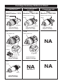
MultiChoice
®
13/14
Grey
Off White
Longer
Lower Housing
Order RP46074 to
Replace Cartridge.
Old
Monitor
®
1300/1400
White
Blue
or
Off White
Shorter Lower Housing
Order RP19804 to
Replace Cartridge.
White
Blue
Shorter Lower Housing
Order RP19804 to
Replace Cartridge.
New
Monitor
®
1300/1400
17
Grey Upper Cap
Shorter Tab
V Notch
Adapter
Order RP46463 to
Replace Cartridge.
1700
White Upper Cap
Longer Tab
Square Notch
Order RP32104 to
Replace Cartridge.
17T
Brass
Black
NA
Will Not Fit
Order RP47201 to
Replace Cartridge.
Cartridge Summary Reference Sheet
Units shipped in March
2006 and after.
Replacement cartridges
shipped in July 2006
and after.
Units shipped before
March 2006.
NA
NA

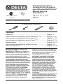
Instrucciones para la
Instalación del Accesorio
para Válvulas MultiChoice
®
Manual para los
Propietarios
13, 14, 17 y 17T
Series
Escriba aquí el número del modelo comprado.
ASME A112.18.1 / CSA B125.1
ASSE 1016
®
®
U
P
C
ESTA VÁLVULA CUMPLE O EXCEDE LAS
SIGUIENTES NORMAS:
ASME A112.18 1 / CSA B125.1 y ASSE 1016.
ADVERTENCIA: El instalador debe apostar
este systema/divisa para garantizar temperatura
maximo y seguro. Cualqueir cambio en el ajuste
puede subir la temperatura del agua de descarga
sobre el límite considerado seguro y puede
resultar en quemaduras de agua caliente.
AVISO PARA EL INSTALADOR: PRECAUCIÓN
– Como instalador de esta válvula, es su
responsabilidad de INSTALAR Y AJUSTAR
apropiadamente esta válvula como se describe
en las instrucciones, por lo tanto, debe haber
una persona para hacer los ajustes necesarios
del Tope del Límite Rotacional y del pomo
para la temperatura en el momento que se
haga la instalación y pueda necesitar ajustes
adicionales por los cambios estacionales
de la temperatura del agua. USTED DEBE
informarle al dueño/usuario sobre este
requisito siguiendo las instrucciones. Si usted
o el dueño/usuario no están seguros como
hacer estos ajustes apropiadamente, por favor
refiérase al Página 5 (series 13 / 14), Página 10
(serie 17) o Página 14 (serie 17T) y si todavía no
está seguro, llámenos al 1-800-345-DELTA.
Después de hacer la instalación y el ajuste,
usted puede agregarle a la etiqueta de aviso
proporcionada, su nombre, el nombre de la
compañía y la fecha cuando ajustó el Tope del
Límite Rotacional y el pomo para la temperatura y
aplicar o fijar la etiqueta al dorso de la puerta del
gabinete más cercano y la etiqueta de aviso al
calentador de agua. Deje la Hoja de Instrucciones
para referencia del dueño/usuario.
ADVERTENCIA: Esta válvula de presión
balanceada y termostática está diseñada
para minimizar los efectos de los cambios
de temperatura de agua por causa de los
cambios de presión en el agua de entrada,
comúnmente causados por lavadoras de
platos, lavadoras de ropa, inodoros, y otros
aparatos por el estilo. Puede no proporcionar
protección de quemaduras de agua caliente
cuando hay alguna falla de otros aparatos
para el control de temperatura en otro
sitio en el sistema de plomería. También
no proporcionará protección si el tope del
límite rotacional y el pomo para el ajuste de
la temperatura no está apropiadamente fijo
o si cambia la temperatura del agua caliente
después de hacer los ajustes o si los cambios
del agua de entrada son por los cambios
estacionales.
ADVERTENCIA: No instale un aparato de corte
o cierre en cualquiera de las tomas de esta
válvula. Cuando este tipo de aparato cierra el
flujo de agua, puede hacer fallar la habilidad
de la válvula de balancear las presiones del
agua caliente y fría.
Contenido:
Garantías ........................................................................... Página 2
Instrucciones de Instalación para la Series 13 / 14............. Páginas 3 -6
Instrucciones de Instalación para la Serie 17...................... Páginas 7-10
Instrucciones de Instalación para la Serie 17T ................... Páginas 11-14
Mantenimiento .................................................................... Páginas 14-15
Hoja resumen de referencia para el cartucho .................... Página 16
Piezas de Repuesto ............................................................Páginas 17-46
1
Usted puede necesitar
T
E
F
L
O
N
4/2/0951975 Rev. D

Todas las piezas y acabados de la llave Delta
®
están garantizados al consumidor comprador
original, de estar libres de defectos de material
y fabricación, por el tiempo que el consumidor
comprador original sea dueño de su casa. Delta
Faucet Company recomienda que use un
plomero profesional para todas las instalaciones
y zreparaciones.
Delta reemplazará, LIBRE DE CARGO, durante
el período de garantía, cualquier pieza o
acabado que pruebe tener defectos de material
y/o fabricación bajo instalación normal, uso y
servicio. Piezas de repuesto pueden ser
obtenidas llamando al 1-800-345-DELTA (en los
Estados Unidos y Canada) o escribiendo a:
En los Estados Unidos:
Delta Faucet Company
Product Service
55 E. 111th Street
Indianapolis, IN 46280
En Canada:
Masco Canada
Technical Service Centre
420 Burbrook Place
London, ON N6A 4L6
Esta garantía es extensiva en lo que cubre el
reemplazamiento de todas las piezas
defectuosas y hasta el acabado, pero éstas
son las únicas dos cosas que están cubiertas.
CARGOS DE LABOR Y/O DAÑOS INCURRIDOS
EN LA INSTALACIÓN, REPARACIÓN, O
REEMPLAZAMIENTO COMO TAMBIÉN
Garantía Limitada De Por Vida de la Llave y su Acabado
CUALQUIER OTRO TIPO DE PÉRDIDA O
DAÑOS ESTÁN EXCLUÍDOS. Prueba de
compra (recibo original de venta) del comprador
consumidor original debe de ser disponible a
Delta para todos los reclamos. ESTA ES LA
GARANTÍA EXCLUSIVA DE DELTA FAUCET
COMPANY, QUE NO HACE CUALQUIER
OTRA GARANTÍA DE CUALQUIER TIPO,
INCLUYENDO LA GARANTÍA IMPLÍCITA DE
COMERCIALIZACIÓN.
Esta garantía excluye todo uso industrial,
comercial y de negocio, a cuyos compradores
se les da una garantía limitada extendida de
cinco años desde la fecha de compra, con todos
los otros términos de esta garantía aplicados,
excepto el de duración de ésta. Esta garantía
es aplicable a las llaves de Delta
®
fabricadas
después de Enero 1, 1995.
Algunos estados/provincias no permiten la
exclusión o limitación de daños incidentales o
consecuentes, de manera que la limitación o
exclusión arriba escrita puede no aplicarle a
usted. Cualquier daño a esta llave, resultado del
mal uso, abuso, o descuido, o cualquier otro uso
de piezas de repuesto que no sean genuinas de
Delta
®
ANULARÁN LA GARANTÍA.
Esta garantía le da derechos legales específicos,
y usted puede, también tener otros derechos que
varían de estado/provincia a estado/provincia.
Es aplicable sólo a las llaves Delta
®
instaladas
en los Estados Unidos de America, Canada
y Mexico.
© 2009 Masco Corporación de Indiana
Todas las piezas de la llave Delta HDF están
garantizadas al dueño original de estar libres de
defectos en materiales y en la mano de obra por
un período de cinco (5) años. Esta garantía se
hace al dueño original y será efectiva el día de la
compra como se ve en el recibo de compra.
Delta reemplazará, LIBRE DE CARGO, durante
el período de la garantía, cualquier pieza que
resulte defectuosa en materiales y/o en la mano
de obra bajo instalación, uso y servicio
normal. Las piezas de repuesto pueden ser
obtenidas de su comerciante o distribuidor local
que se encuentran en la guía telefónica o si
usted devuelve la pieza con el recibo de compra
a nuestra fabrica, Y LOS CARGOS DE
TRANSPORTE PAGADOS CON ANTELACION,
a la dirección dada. ESTA GARANTIA ES LA
UNICA GARANTIA EXPRESA DE DELTA.
CUALQUIER RECLAMO HECHO BAJO ESTA
GARANTIA TIENE QUE SER HECHO
DURANTE EL PERIODO DE CINCO AÑOS A
QUE SE REFIERE ARRIBA. CUALQUIER
GARANTIA IMPLICITA, INCLUYENDO LA
GARANTIA IMPLICITA DE
COMERCIALIZACION O CONVENIENCIA
PARA UN PROPOSITO PARTICULAR, SON
LIMITADOS EN DURACION A LA DURACION
DE ESTA GARANTIA. LOS CARGOS PARA LA
MANO DE OBRA Y/O DAÑOS INCURRIDOS EN
LA INSTALACION, REPARACION O
REEMPLAZO, ASI COMO LOS DAÑOS
INCIDENTALES O CONSECUENTES
CONECTADOS CON ELLOS SON EXCLUIDOS
Y NO SERAN PAGADOS POR DELTA.
Algunos estados no permiten limitaciones al
tiempo que dura la garantía implícita, o la
exclusión o limitación de los daños incidentales o
consecuentes, así que la limitación o exclusión
expresada arriba puede no ser aplicable a usted.
Esta garantía le da a usted derechos legales
específicos y usted puede también tener otros
derechos que varían de estado a estado.
Esta garantía es nula por cualquier daño a esta
llave que sea el resultado del mal uso, abuso,
negligencia, accidente, instalación impropia,
cualquier uso en violación de las instrucciones
suministradas por nosotros o cualquier uso de
piezas de repuesto que no sean piezas
genuinas Delta.
Garantia Limitada de Delta HDF
2
© 2009 Masco Corporación de Indiana
La page charge ...
La page charge ...
La page charge ...
La page charge ...
La page charge ...
La page charge ...
La page charge ...
La page charge ...
La page charge ...
La page charge ...
La page charge ...
La page charge ...
La page charge ...
La page charge ...
La page charge ...
La page charge ...
La page charge ...
La page charge ...
La page charge ...
La page charge ...
La page charge ...
La page charge ...
La page charge ...
La page charge ...
La page charge ...
La page charge ...
La page charge ...
La page charge ...
La page charge ...
La page charge ...
La page charge ...
La page charge ...
La page charge ...
La page charge ...
La page charge ...
La page charge ...
La page charge ...
La page charge ...
La page charge ...
La page charge ...
La page charge ...
La page charge ...
La page charge ...
La page charge ...
La page charge ...
La page charge ...
La page charge ...
La page charge ...
La page charge ...
La page charge ...
La page charge ...
La page charge ...
La page charge ...
La page charge ...
La page charge ...
La page charge ...
La page charge ...
La page charge ...
La page charge ...
La page charge ...
La page charge ...
La page charge ...
-
 1
1
-
 2
2
-
 3
3
-
 4
4
-
 5
5
-
 6
6
-
 7
7
-
 8
8
-
 9
9
-
 10
10
-
 11
11
-
 12
12
-
 13
13
-
 14
14
-
 15
15
-
 16
16
-
 17
17
-
 18
18
-
 19
19
-
 20
20
-
 21
21
-
 22
22
-
 23
23
-
 24
24
-
 25
25
-
 26
26
-
 27
27
-
 28
28
-
 29
29
-
 30
30
-
 31
31
-
 32
32
-
 33
33
-
 34
34
-
 35
35
-
 36
36
-
 37
37
-
 38
38
-
 39
39
-
 40
40
-
 41
41
-
 42
42
-
 43
43
-
 44
44
-
 45
45
-
 46
46
-
 47
47
-
 48
48
-
 49
49
-
 50
50
-
 51
51
-
 52
52
-
 53
53
-
 54
54
-
 55
55
-
 56
56
-
 57
57
-
 58
58
-
 59
59
-
 60
60
-
 61
61
-
 62
62
-
 63
63
-
 64
64
-
 65
65
-
 66
66
-
 67
67
-
 68
68
-
 69
69
-
 70
70
-
 71
71
-
 72
72
-
 73
73
-
 74
74
-
 75
75
-
 76
76
-
 77
77
-
 78
78
-
 79
79
-
 80
80
-
 81
81
-
 82
82


Delta Hot Tub T17T282 Manuel utilisateur
- Catégorie
- Articles sanitaires
- Taper
- Manuel utilisateur
dans d''autres langues
- English: Delta Hot Tub T17T282 User manual
- español: Delta Hot Tub T17T282 Manual de usuario
Documents connexes
-
Delta 1700 Series Guide d'installation
-
-
-
Delta T14499-BL Manuel utilisateur
-
-
Delta T14474 Manuel utilisateur
-
Delta Faucet T13220-SHC Manuel utilisateur
-
Delta Faucet T14451-RBH2O Guide d'installation
-
-
Delta T14467-H2O Guide d'installation
Autres documents
-
Delta Faucet T13691 Manuel utilisateur
-
Peerless PTT14219-BN Information produit
-
Peerless PTT14023-BN Guide d'installation
-
-
American Standard 131531 Guide d'installation
-
 Lincoln Products 121160 Guide d'installation
-
-
-
Delta Faucet RP63135 Guide d'installation
-
