Bosch 1821 Manuel utilisateur
- Catégorie
- Outils électroportatifs
- Taper
- Manuel utilisateur

IMPORTANT: IMPORTANT : IMPORTANTE:
Read Before Using Lire avant usage Leer antes de usar
Operating/Safety Instructions
Consignes de fonctionnement/sécurité
Instrucciones de funcionamiento y seguridad
1821
1821D
For English Version Version française Versión en español
See page 2 Voir page 18 Ver la página 34
1-877-BOSCH99 (1-877-267-2499) www.boschtools.com
Call Toll Free for
Consumer Information
& Service Locations
Pour obtenir des informations
et les adresses de nos centres
de service après-vente,
appelez ce numéro gratuit
Llame gratis para
obtener información
para el consumidor y
ubicaciones de servicio
BM 1609929Y07 10-10:BM 1609929Y07 10-10 1/18/11 10:05 AM Page 1

-2-
Read all safety warnings
and all instructions. Failure
to follow the warnings and instructions may
result in electric shock, fire and/or serious
injury.
SAVE ALL WARNINGS AND
INSTRUCTIONS FOR FUTURE
REFERENCE
The term “power tool” in the warnings refers to
your mains-operated (corded) power tool or
battery-operated (cordless) power tool.
1) Work area safety
a) Keep work area clean and well lit.
Cluttered or dark areas invite accidents.
b) Do not operate power tools in explosive
atmospheres, such as in the presence of
flammable liquids, gases or dust. Power
tools create sparks which may ignite the
dust or fumes.
c) Keep children and bystanders away
while operating a power tool. Distractions
can cause you to lose control.
2) Electrical safety
a) Power tool plugs must match the outlet.
Never modify the plug in any way. Do not
use any adapter plugs with earthed
(grounded) power tools. Unmodified plugs
and matching outlets will reduce risk of
electric shock.
b) Avoid body contact with earthed or
grounded surfaces such as pipes,
radiators, ranges and refrigerators. There
is an increased risk of electric shock if your
body is earthed or grounded.
c) Do not expose power tools to rain or wet
conditions. Water entering a power tool will
increase the risk of electric shock.
d) Do not abuse the cord. Never use the
cord for carrying, pulling or unplugging
the power tool. Keep cord away from
heat, oil, sharp edges or moving parts.
Damaged or entangled cords increase the
risk of electric shock.
e) When operating a power tool outdoors,
use an extension cord suitable for
outdoor use. Use of a cord suitable for
outdoor use reduces the risk of electric
shock.
f) If operating a power tool in a damp
location is unavoidable, use a Ground
Fault Circuit Interrupter (GFCI) protected
supply. Use of an GFCI reduces the risk of
electric shock.
3) Personal safety
a) Stay alert, watch what you are doing and
use common sense when operating a
power tool. Do not use a power tool while
you are tired or under the influence of
drugs, alcohol or medication. A moment
of inattention while operating power tools
may result in serious personal injury.
b) Use personal protective equipment.
Always wear eye protection. Protective
equipment such as dust mask, non-skid
safety shoes, hard hat, or hearing protection
used for appropriate conditions will reduce
personal injuries.
c) Prevent unintentional starting. Ensure
the switch is in the off-position before
connecting to power source and / or
battery pack, picking up or carrying the
tool. Carrying power tools with your finger
on the switch or energizing power tools that
have the switch on invites accidents.
d) Remove any adjusting key or wrench
before turning the power tool on. A
wrench or a key left attached to a rotating
part of the power tool may result in personal
injury.
e) Do not overreach. Keep proper footing
and balance at all times. This enables
better control of the power tool in
unexpected situations.
f) Dress properly. Do not wear loose
clothing or jewelry. Keep your hair,
clothing and gloves away from moving
parts. Loose clothes, jewelry or long hair
can be caught in moving parts.
g) If devices are provided for the
connection of dust extraction and
collection facilities, ensure these are
connected and properly used. Use of dust
collection can reduce dust-related hazards.
4) Power tool use and care
a) Do not force the power tool. Use the
correct power tool for your application.
The correct power tool will do the job better
and safer at the rate for which it was designed.
!
WARNING
General Power Tool Safety Warnings
BM 1609929Y07 10-10:BM 1609929Y07 10-10 1/18/11 10:05 AM Page 2

Power Tool-Specific Safety Warnings
Safety Warnings Common for Grinding,
Sanding, Wire Brushing, and Abrasive
Cutting-Off Operations:
a) This power tool is intended to function
as a grinder, sander, wire brush or cut-
off tool. Read all safety warnings,
instructions, illustrations and
specifications provided with this power
tool. Failure to follow all instructions listed
below may result in electric shock, fire
and/or serious injury.
b) This power tool is not recommended for
polishing. Operations for which the power
tool was not designed may create a hazard
and cause personal injury.
c) Do not use accessories which are not
specifically designed and recommended
by the tool manufacturer. Just because
the accessory can be attached to your
power tool, it does not assure safe
operation.
d) The rated speed of the accessory must
be at least equal to the maximum speed
marked on the power tool. Accessories
running faster than their RATED SPEED
can break and fly apart.
e) The outside diameter and the thickness
of your accessory must be within the
capacity rating of your power tool.
Incorrectly sized accessories cannot be
adequately guarded or controlled.
f) The arbor size of wheels, flanges,
backing pads or any other accessory
must properly fit the spindle of the
power tool. Accessories with arbor holes
that do not match the mounting hardware of
the power tool will run out of balance,
vibrate excessively and may cause loss of
control.
g) Do not use a damaged accessory. Before
each use inspect the accessory such as
abrasive wheels for chips and cracks,
backing pad for cracks, tear or excess
wear, wire brush for loose or cracked
wires. If power tool or accessory is
dropped, inspect for damage or install an
undamaged accessory. After inspecting
and installing an accessory, position
yourself and bystanders away from the
plane of the rotating accessory and run
the power tool at maximum no-load
speed for one minute. Damaged
accessories will normally break apart during
this test time.
b) Do not use the power tool if the switch
does not turn it on and off. Any power tool
that cannot be controlled with the switch is
dangerous and must be repaired.
c) Disconnect the plug from the power
source and/or the battery pack from the
power tool before making any
adjustments, changing accessories, or
storing power tools. Such preventive
safety measures reduce the risk of starting
the power tool accidentally.
d) Store idle power tools out of the reach of
children and do not allow persons
unfamiliar with the power tool or these
instructions to operate the power tool.
Power tools are dangerous in the hands of
untrained users.
e) Maintain power tools. Check for
misalignment or binding of moving parts,
breakage of parts and any other
condition that may affect the power
tool’s operation. If damaged, have the
power tool repaired before use. Many
accidents are caused by poorly maintained
power tools.
f) Keep cutting tools sharp and clean.
Properly maintained cutting tools with sharp
cutting edges are less likely to bind and are
easier to control.
g) Use the power tool, accessories and tool
bits etc. in accordance with these
instructions, taking into account the
working conditions and the work to be
performed. Use of the power tool for
operations different from those intended
could result in a hazardous situation.
5) Service
a) Have your power tool serviced by a
qualified repair person using only
identical replacement parts. This will
ensure that the safety of the power tool is
maintained.
-3-
BM 1609929Y07 10-10:BM 1609929Y07 10-10 1/18/11 10:05 AM Page 3

h) Wear personal protective equipment.
Depending on application, use face
shield, safety goggles or safety glasses.
As appropriate, wear dust mask, hearing
protectors, gloves and workshop apron
capable of stopping small abrasive or
workpiece fragments. The eye protection
must be capable of stopping flying debris
generated by various operations. The eye
protection must be capable of stopping flying
debris generated by various operations. The
dust mask or respirator must be capable of
filtrating particles generated by your
operation. Prolonged exposure to high
intensity noise may cause hearing loss.
i) Keep bystanders a safe distance away
from work area. Anyone entering the
work area must wear personal protective
equipment. Fragments of workpiece or of a
broken accessory may fly away and cause
injury beyond immediate area of operation.
j) Hold power tool by insulated gripping
surfaces only, when performing an
operation where the cutting accessory
may contact hidden wiring or its own
cord. Cutting accessory contacting a “live”
wire may make exposed metal parts of the
power tool “live” and shock the operator.
k) Position the cord clear of the spinning
accessory. If you lose control, the cord may
be cut or snagged and your hand or arm
may be pulled into the spinning accessory.
l) Never lay the power tool down until the
accessory has come to a complete stop.
The spinning accessory may grab the
surface and pull the power tool out of your
control.
m)Do not run the power tool while carrying
it at your side. Accidental contact with the
spinning accessory could snag your
clothing, pulling the accessory into your
body.
n) Regularly clean the power tool’s air
vents. The motor’s fan will draw the dust
inside the housing and excessive
accumulation of powdered metal may cause
electrical hazards.
o) Do not operate the power tool near
flammable materials. Sparks could ignite
these materials.
p) Do not use accessories that require
liquid coolants. Using water or other liquid
coolants may result in electrocution or
shock.
Kickback and Related Warnings
Kickback is a sudden reaction to a pinched or
snagged rotating wheel, backing pad, brush or
any other accessory. Pinching or snagging
causes rapid stalling of the rotating accessory
which in turn causes the uncontrolled power
tool to be forced in the direction opposite of the
accessory’s rotation at the point of the binding.
For example, if an abrasive wheel is snagged
or pinched by the workpiece, the edge of the
wheel that is entering into the pinch point can
dig into the surface of the material causing the
wheel to climb out or kickout. The wheel may
either jump toward or away from the operator,
depending on direction of the wheel’s
movement at the point of pinching. Abrasive
wheels may also break under these conditions.
Kickback is the result of power tool misuse
and/or incorrect operating procedures or
conditions and can be avoided by taking proper
precautions as given below.
a) Maintain a firm grip on the power tool
and position your body and arm to allow
you to resist kickback forces. Always use
auxiliary handle, if provided, for
maximum control over kickback or
torque reaction during start-up. The
operator can control torque reactions or
kickback forces, if proper precautions are
taken.
b) Never place your hand near the rotating
accessory. Accessory may kickback over
your hand.
c) Do not position your body in the area
where power tool will move if kickback
occurs. Kickback will propel the tool in
direction opposite to the wheel’s movement
at the point of snagging.
d) Use special care when working corners,
sharp edges etc. Avoid bouncing and
snagging the accessory. Corners, sharp
edges or bouncing have a tendency to snag
the rotating accessory and cause loss of
control or kickback.
e) Do not attach a saw chain woodcarving
blade or toothed saw blade. Such blades
create frequent kickback and loss of control.
Safety Warnings Specific for Grinding and
Abrasive Cutting-Off Operations:
a) Use only wheel types that are
recommended for your power tool and
the specific guard designed for the
selected wheel. Wheels for which the
-4-
BM 1609929Y07 10-10:BM 1609929Y07 10-10 1/18/11 10:05 AM Page 4

power tool was not designed cannot be
adequately guarded and are unsafe.
b) The guard must be securely attached to
the power tool and positioned for
maximum safety, so the least amount of
wheel is exposed towards the operator.
The guard helps to protect operator from
broken wheel fragments and accidental
contact with wheel.
c) Wheels must be used only for
recommended applications. For
example: do not grind with the side of
cut-off wheel. Abrasive cut-off wheels are
intended for peripheral grinding, side forces
applied to these wheels may cause them to
shatter.
d) Always use undamaged wheel flanges
that are of correct size and shape for
your selected wheel. Proper wheel flanges
support the wheel thus reducing the
possibility of wheel breakage. Flanges for
cut-off wheels may be different from grinding
wheel flanges.
e) Do not use worn down wheels from
larger power tools. Wheel intended for
larger power tool is not suitable for the
higher speed of a smaller tool and may
burst.
Additional Safety Warnings Specific for
Abrasive Cutting-Off Operations:
Do not attempt to cut large stock or sheets
of metal as this machine is not designed to
be a dedicated cut-off machine.
a) Do not “jam” the cut-off wheel or apply
excessive pressure. Do not attempt to
make an excessive depth of cut.
Overstressing the wheel increases the
loading and susceptibility to twisting or
binding of the wheel in the cut and the
possibility of kickback or wheel breakage.
b) Do not position your body in line with
and behind the rotating wheel. When the
wheel, at the point of operation, is moving
away from your body, the possible kickback
may propel the spinning wheel and the
power tool directly at you.
c) When wheel is binding or when
interrupting a cut for any reason, switch
off the power tool and hold the power
tool motionless until the wheel comes to
a complete stop. Never attempt to
remove the cut-off wheel from the cut
while the wheel is in motion otherwise
kickback may occur. Investigate and take
corrective action to eliminate the cause of
wheel binding.
d) Do not restart the cutting operation in the
workpiece. Let the wheel reach full speed
and carefully reenter the cut. The wheel
may bind, walk up or kickback if the power
tool is restarted in the workpiece.
e) Support panels or any oversized
workpiece to minimize the risk of wheel
pinching and kickback. Large workpieces
tend to sag under their own weight.
Supports must be placed under the
workpiece near the line of cut and near the
edge of the workpiece on both sides of the
wheel.
f) Use extra caution when making a
“pocket cut” into existing walls or other
blind areas. The protruding wheel may cut
gas or water pipes, electrical wiring or
objects that can cause kickback.
Do not use type 1 abrasive wheels designed
for straight grinding.
Safety Warnings Specific for Sanding
Operations:
a) Do not use excessively oversized sanding
disc paper. Follow manufacturer’s
recommendations, when selecting
sanding paper. Larger sanding paper
extending beyond the sanding pad presents
a laceration hazard and may cause
snagging, tearing of the disc or kickback.
Safety Warnings Specific for Wire Brushing
Operations:
a) Be aware that wire bristles are thrown by
the brush even during ordinary
operation. Do not overstress the wires
by applying excessive load to the brush.
The wire bristles can easily penetrate light
clothing and/or skin.
b) If the use of a guard is recommended for
wire brushing, do not allow any
interference of the wire wheel or brush
with the guard. Wire wheel or brush may
expand in diameter due to work load and
centrifugal forces.
-5-
BM 1609929Y07 10-10:BM 1609929Y07 10-10 1/18/11 10:05 AM Page 5

GFCI and personal protection devices like
electrician’s rubber gloves and footwear will
further enhance your personal safety.
Do not use AC only rated tools with a DC
power supply. While the tool may appear to
work, the electrical components of the AC
rated tool are likely to fail and create a hazard
to the operator.
Keep handles dry, clean and free from oil
and grease. Slippery hands cannot safely
control the power tool.
Use clamps or other practical way to secure
and support the workpiece to a stable
platform. Holding the work by hand or against
your body is unstable and may lead to loss of
control.
Develop a periodic maintenance schedule
for your tool. When cleaning a tool be
careful not to disassemble any portion of
the tool since internal wires may be
misplaced or pinched or safety guard return
springs may be improperly mounted.
Certain cleaning agents such as gasoline,
carbon tetrachloride, ammonia, etc. may
damage plastic parts.
Risk of injury to user. The power cord must only
be serviced by a Bosch Factory Service Center
or Autho rized Bosch Service Station.
Use hand guard when sanding and
brushing.
Do not use type 1 wheels for face grinding.
Side forces applied to type 1 wheels may cause
them to shatter or burst.
Some dust created by power
sanding, sawing, grinding,
drilling, and other construction activities
contains chemicals known to cause cancer,
birth defects or other reproductive harm.
Some examples of these chemicals are:
• Lead from lead-based paints,
• Crystalline silica from bricks and cement and
other masonry products, and
• Arsenic and chromium from chemically-
treated lumber.
Your risk from these exposures varies,
depending on how often you do this type of
work. To reduce your exposure to these
chemicals: work in a well ventilated area, and
work with approved safety equipment, such as
those dust masks that are specially designed
to filter out microscopic particles.
-6-
Additional Safety Warnings
!
WARNING
BM 1609929Y07 10-10:BM 1609929Y07 10-10 1/18/11 10:05 AM Page 6

-7-
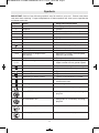
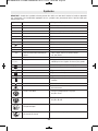
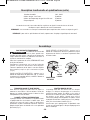
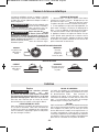
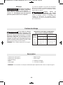
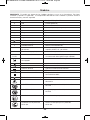
IMPORTANT: Some of the following symbols may be used on your tool. Please study them
and learn their meaning. Proper interpretation of these symbols will allow you to operate the
tool better and safer.
Symbol Name Designation/Explanation
V Volts Voltage (potential)
A Amperes Current
Hz Hertz Frequency (cycles per second)
W Watt Power
kg Kilograms Weight
min Minutes Time
s Seconds Time
Diameter Size of drill bits, grinding wheels, etc.
n
0
No load speed Rotational speed, at no load
n Rated speed Maximum attainable speed
.../min Revolutions or reciprocation Revolutions, strokes, surface speed,
per minute orbits etc. per minute
0 Off position Zero speed, zero torque...
1, 2, 3, ... Selector settings Speed, torque or position settings.
I, II, III, Higher number means greater speed
Infinitely variable selector with off Speed is increasing from 0 setting
Arrow Action in the direction of arrow
Alternating current Type or a characteristic of current
Direct current Type or a characteristic of current
Alternating or direct current Type or a characteristic of current
Class II construction Designates Double Insulated
Construction tools.
Earthing terminal Grounding terminal
Warning symbol Alerts user to warning messages
Li-ion RBRC seal Designates Li-ion battery recycling
program
Ni-Cad RBRC seal Designates Ni-Cad battery recycling
program
Read manual symbol Alerts user to read manual
Wear eye protection symbol Alerts user to wear eye protection
Symbols
0
BM 1609929Y07 10-10:BM 1609929Y07 10-10 1/18/11 10:05 AM Page 7

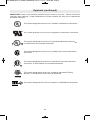
-8-
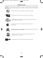
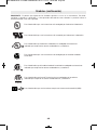
This symbol designates that this tool is listed by Underwriters Laboratories.
This symbol designates that this tool is listed by the Canadian Standards
Association.
This symbol designates that this tool is listed by the Canadian Standards
Association, to United States and Canadian Standards.
This symbol designates that this tool complies to NOM Mexican Standards.
This symbol designates that this tool is listed by Underwriters Laboratories,
to United States and Canadian Standards.
This symbol designates that this tool is listed by the Intertek Testing
Services, to United States and Canadian Standards.
Symbols (continued)
IMPORTANT: Some of the following symbols may be used on your tool. Please study them
and learn their meaning. Proper interpretation of these symbols will allow you to operate the
tool better and safer.
This symbol designates that this tool is recognized by Underwriters Laboratories.
BM 1609929Y07 10-10:BM 1609929Y07 10-10 1/18/11 10:06 AM Page 8

-9-
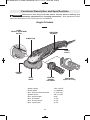
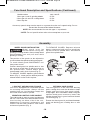
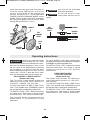
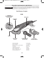
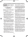
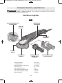
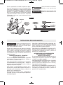
Functional Description and Specifications
Disconnect the plug from the power source before making any
assembly, adjustments or changing accessories. Such preventive safety
measures reduce the risk of starting the tool accidentally.
!
WARNING
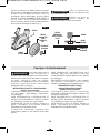
Angle Grinders
Model number 1821, 1821D
* Rated speed n 11,000/min
* Max. abrasive wheel diameter 5" (125 mm)
Spindle thread 5/8"-11 UNC
Max. spindle length 9/16"
Max. wire wheel 4" Dia.
Max. wire cup brush 3" Dia.
* Max. sanding disc 5" Dia.
GUARD
RELEASE / ADJUSTMENT
BUTTON
VENTILATION
OPENINGS
GRINDING
WHEEL
WHEEL
GUARD
HAND GUARD
(Optional Accessory)
VIBRATION
CONTROL
SIDE HANDLE
SPINDLE LOCK
FIG. 1
PADDLE
SWITCH
BM 1609929Y07 10-10:BM 1609929Y07 10-10 1/18/11 10:06 AM Page 9

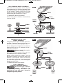
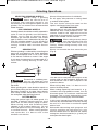
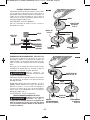
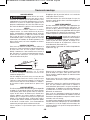
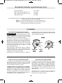
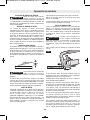
WHEEL GUARD INSTALLATION
Wheel guard must be
attached when using disc
grinding or cutting wheels. Always keep wheel
guard be tween you and your work while
grinding or cutting.
The position of the guard can be adjusted to
accommodate the operation being performed.
To attach wheel guard DISCONNECT tool
from power source.
Position wheel guard on spindle neck so that
the arrow on guard lines up with the arrow on
the spindle neck. Rotate wheel guard
clockwise 90º until it clicks in place (Fig. 2).
TO ADJUST GUARD: depress guard release
button (Fig. 1), rotate guard to desired position,
release button and let it click in place.
TO REMOVE GUARD: Depress release
button, rotate guard until arrow on guard lines
up with arrow on spindle neck, and remove
guard from spindle neck.
Assembly
-10-
LOCK NUT AND BACKING FLANGE
Your tool is equipped with a threaded spindle
for mounting ac ces sories. Always use the
supplied lock nut (and backing flange) that
has same thread size as spindle.
VIBRATION CONTROL SIDE HANDLE
The side handle is used to control and balance
the tool. The handle must be thread ed into the
front housing on either side of the tool,
depending on per sonal preference and
comfort. Use the side handle for safe control
and ease of operation (Fig. 1).
OPTIONAL HAND GUARD
The hand guard is to be used with backing
pads, sanding discs and wire brushes to keep
fingers and hand away from work surface,
sharp edges, burrs and debris. When using the
optional hand guard accessory insert side
handle through hole in guard and then thread
into housing (Fig. 1).
Ensure that hand guard is positioned between
hand and backing pad, sanding disc or wire
brush.
!
WARNING
WHEEL
GUARD
SPINDLE
NECK
FIG. 2
* NOTE: For tool specifications refer to the nameplate on your tool.
Accessory speed rating must be equal to or greater than the tool’s speed rating. Do not
exceed the recommended wheel diameter.
NOTE: Not recommended for use with type 11 cup wheels.
Model number 1821, 1821D
Max. type 1 and 27 grinding wheels 5" Dia.
* Max. type 1A and 27A cutting wheel 5" Dia.
* Max. flap disc 5" Dia.
Functional Description and Specifications (Continued)
BM 1609929Y07 10-10:BM 1609929Y07 10-10 1/18/11 10:06 AM Page 10

-11-
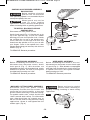
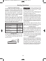
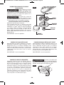
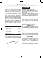
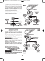
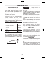
DISC GRINDING WHEEL ASSEMBLY
Disconnect tool from power source. Be sure
that wheel guard is in place for grinding. Place
BACKING FLANGE and GRINDING WHEEL
on the spindle. Thread on the lock nut and
tighten nut using the supplied lock nut wrench,
while holding the spindle lock in (Fig. 3).
TO REMOVE: Reverse procedure.
When using spin-on wheels, thread directly
onto the spindle.
LOCK NUT
TYPE 27
GRINDING
WHEEL
BACKING
FLANGE
SPINDLE
TYPE 27
GRINDING
WHEEL
LOCK NUT
SPINDLE
TYPE 27
WHEEL GUARD
BACKING
FLANGE
FIG. 3
TYPE 27 SPIN-ON
GRINDING WHEEL
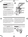
ABRASIVE TYPE 1A & 27A
WHEEL ASSEMBLY
Using the optional type 1A wheel guard, it is
possible to perform limited cutting on small
stock such as metal tubes, piping or rebar.
Do not attempt to cut large stock or sheets of
metal as this tool is not designed to be a
dedicated cutting tool.
Always use type 1A protection
guard for cutting.
Disconnect tool from power source. Be sure
that wheel guard is in place for cutting.
When using mounting wheels, thread
BACKING FLANGE onto spindle, then place
WHEEL on the spindle. Thread on the lock
nut and tighten nut using a lock nut wrench
provided with adapter kit, while holding the
spindle lock in (Fig. 4).
TO REMOVE: Reverse procedure.
TYPE 1 ABRASIVE
STRAIGHT GRINDING WHEELS
Do not use type 1 abrasive
wheels designed for
straight/die grinding. This tool is not
designed for use with type 1 abrasive
straight/die grinding wheels.
!
WARNING
!
WARNING
TYPE 1A
WHEEL GUARD
SPINDLE
BACKING
FLANGE
TYPE 1A
(ISO41)
CUTTING
WHEEL
FIG. 4
LOCK NUT
TYPE 27A
CUTOFF
WHEEL
BM 1609929Y07 10-10:BM 1609929Y07 10-10 1/18/11 10:06 AM Page 11

MASONRY CUTTING WHEEL ASSEMBLY
Disconnect plug from power source.
Completely unscrew the four screws and
rotate the tool head carefully to the new
position without removing it from the housing.
For paddle switch tools, switch should face
“down” towards work surface. For slide switch
tools, slide should face “up” towards user, so
the tool can be used for long masonry cutting
applications. Screw in and tighten the four
screws again. (Fig. 6)
Return tool head to original
position when returning to
grinding, sanding, brushing or metal cutting
applications.
FIG. 6
SANDING ACCESSORIES ASSEMBLY
BACKING PAD
Before attaching a backing
pad be sure its maximum
safe operating speed is not exceeded by the
nameplate speed of the tool.
Wheel guard may not be
used for most sanding
operations. Always reinstall wheel guard
when converting back to grinding operations.
TO INSTALL BACKING PAD AND
SANDING DISC
Disconnect tool from power source.
Attach hand guard (Fig. 1). Set the tool on its
top side (spindle up). Place the rubber
backing pad onto the spindle shaft. Center
the sanding disc on top of the backing pad.
Insert the lock nut through the disc and
thread onto the spindle as far as you can with
your fingers. Press in the spindle lock, then
tighten the backing pad securely with lock nut
wrench (Fig. 5).
TO REMOVE: Reverse procedure.
-12-
!
WARNING
!
WARNING
WIRE BRUSH ASSEMBLY
Before assembling wire brush to this tool,
disconnect from the power source. Attach
hand guard (Fig. 1). Wire brushes are
equipped with their own threaded hub, simply
thread on to spindle. Be sure to seat against
shoulder before turning tool “ON”.
TO REMOVE: Reverse procedure.
WIRE WHEEL ASSEMBLY
Before assembling wire wheel to this tool,
disconnect from the power source. Attach type
27 guard (Fig. 2). Wire wheeels are equipped
with their own threaded hub, simply thread on
to spindle. Be sure to seat against shoulder
before turning tool “ON”.
TO REMOVE: Reverse procedure.
!
WARNING
SANDING
DISC
BACKING
PAD
LOCK NUT
WIRE
BRUSH
SPINDLE
FIG. 5
BM 1609929Y07 10-10:BM 1609929Y07 10-10 1/18/11 10:06 AM Page 12

Operating Instructions
-13-
Install dust extraction guard with foot plate for
masonry cutting applications so that the
rotation of the wheel will be towards the
vacuum extraction port. Place BACKING
FLANGE and DRY DIAMOND WHEEL on the
spindle. Thread on the LOCK NUT and tighten
nut using the supplied lock nut wrench, while
holding the spindle lock in. (Fig. 7)
Use only lock nut and flange
with equal diameters.
Do not use water or other
cooling fluid with this tool for
cutting.
FIG. 7
SPINDLE
LOCK
NUT
BACKING
FLANGE
DRY
DIAMOND
WHEEL
LOCK NUT
BACKING
FLANGE
SPINDLE
DRY
DIAMOND
WHEEL
!
WARNING
!
WARNING
Hold the tool with both hands
while starting the tool, since
torque from the motor can cause the tool to twist.
Start the tool before applying to work and let
the tool come to full speed before contacting
the workpiece. Lift the tool from the work
before releasing the switch. DO NOT turn the
switch “ON” and “OFF” while the tool is under
load; this will greatly decrease the switch life.
"TRI-CONTROL" PADDLE SWITCH
(Models 1821 only)
The “Tri-Control” Paddle Switch enables the
operator to control the switch functions of
"Lock-OFF", "ON/OFF" and "Lock-ON".
TO UNLOCK SWITCH AND TURN TOOL
"ON": Push paddle lever FORWARD (toward
the spindle) then squeeze the paddle lever.
TO SWITCH TOOL "OFF": Release pressure
on paddle lever. The switch is spring loaded
and will return to "OFF" position automatically.
The "Lock-ON" feature, incorporated into the
paddle switch, is a convenience for long
operations.
TO LOCK SWITCH "ON": After paddle switch
has been activated push paddle lever completely
FORWARD and release paddle lever.
TO SWITCH TOOL "OFF": Squeeze and then
release paddle lever. The switch is spring
loaded and will return to "OFF" position
automatically.
PADDLE SWITCH WITH
"LOCK-OFF "FEATURE
(Model 1821D only
The Paddle switch enables the operator to
control the switch functions of "Lock-OFF",
and "ON/OFF".
TO UNLOCK SWITCH AND TURN TOOL
"ON": Push paddle lever FORWARD (toward
the spindle) then squeeze the paddle lever.
TO SWITCH TOOL "OFF": Release pressure
on paddle lever. The switch is spring loaded
and will return to "OFF" position automatically.
!
WARNING
BM 1609929Y07 10-10:BM 1609929Y07 10-10 1/18/11 10:06 AM Page 13

-14-
SELECTING GRINDING WHEELS
Before using a grinding
wheel, be certain that its
maximum safe operating speed is not
exceeded by the nameplate speed of the
grinder. Do not exceed the recom mended
wheel diameter.
DISC GRINDING WHEELS
Grinding wheels should be carefully selected in
order to use the grinder most efficiently.
Wheels vary in type of abrasive, bond,
hardness, grit size and structure. The correct
type of wheel to use is determined by the job.
Use disc grinding wheels for fast grinding of
structural steel, heavy weld beads, steel
casting, stainless steel and other ferrous
metals.
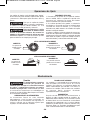
GRINDING TIPS
Efficient grinding is achieved by controlling the
pressure and keep ing the angle between
wheel and workpiece at 10° to 15°. If the wheel
is flat, the tool is difficult to control. If the angle
is too steep, the pressure is concentrated on a
small area causing burning to the work
surface.
Excessive or sudden pres-
sure on the wheel will slow
grinding action and put dangerous stresses on
the wheel.
When grinding with a new wheel be certain to
grind while pulling tool backwards until wheel
becomes rounded on its edge. New wheels
have sharp corners which tend to “bite” or cut
into work piece when pushing forward.
CUTTING METAL
Using the optional type 1A wheel guard, it is
possible to perform limited cutting on small
stock such as metal tubes, piping or rebar.
When cutting, work with moderate feed,
adapted to the material being cut. Do not
exert side pressure onto the cutting disc, tilt
or oscillate the tool. When cutting profiles
and square bar, it is best to start at the
smallest cross section.
Always follow precautions for kickback.
Do not apply side pressure to cutting wheel
to reduce wheel speed.
The tool should always be used so that
sparks are directed away from user.
CUTTING MASONRY
Operate the tool only with dust extraction and
additionally wear a dust protection mask. The
vacuum used for this application must be
approved for the extraction of masonry dust.
Bosch sells suitable vacuum cleaners.
When cutting masonry always
use dust extraction with foot
plate. The tool may be used only for dry
cutting. When cutting masonry use a dry
diamond wheel.
Always cut towards the dust extraction port
(Fig. 8).
Turn the tool on and place the front part of the
cutting guide on the workpiece. Slide the tool
with moderate rate of feed, adapted to the
material to be cut.
When doing deep cuts, it is best to cut in
several shallow passes.
When cutting especially hard material, e. g.,
concrete with high pebble content, the dry
diamond wheel can overheat and become
damaged. This is clearly indicated by circular
sparking of the rotating dry diamond wheel.
In this case, interrupt the cutting process and
allow the dry diamond wheel to cool by running
the tool for a short time at maximum speed
with no load.
Noticeable decreasing work progress and
circular sparking are indications of a dry
diamond wheel that has become dull. Briefly
cutting into abrasive materials (e. g. brick) can
resharpen the wheel again.
!
WARNING
Grinding Operations
!
WARNING
!
WARNING
FIG. 8
BM 1609929Y07 10-10:BM 1609929Y07 10-10 1/18/11 10:06 AM Page 14

SELECTING SANDING DISC
Sanding discs are made of extremely hard
and sharp aluminum oxide grits, phenol-resin
bonded to a sturdy fiber backing for fast
heavy-duty service and long life. The discs
vary as to size and spacing of the abrasive
grits. OPEN COAT (type H) — used for soft
materials and on paint or varnish. CLOSED
COAT (type K) —used for metal, hardwood,
stone, marble and other materials.
Sanding discs range in grit from 16 (very
coarse) to 180 (very fine). To obtain best
results, select sanding discs carefully. Many
jobs require the use of several grit sizes and
at times both “open coat and closed coat”
discs are required to get the job done faster.
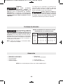
See chart for application examples.
Operation: Refinishing painted wood or metal surfaces.
REMARKS GRIT
To remove paint and to smooth Coarse
surface irregularities. 16-24-30
To smooth Medium
the rough sanding. 36-50-80
To remove scratches left by Fine
previous discs. 100-120
To smooth surfaces for painting, Very Fine
polishing or waxing. 150-180
SANDING TIPS
For best results, tilt the Disc Sander at a 10°
to 15° angle while sanding so that only about
1" of the surface around the edge of the disc
contacts the work.
If the disc (accessory) is held
flat or the back edge of the
disc comes in contact with the work, a violent
thrust to the side may result.
If sander is tilted too much, sanding action will
be too great and a rough cut surface or
gouging and snagging will result.
Guide the Disc Sander with crosswise strokes.
Be careful not to hold the sander in one spot
too long. Do not use a circular motion, as this
makes swirl marks. Test before use on scrap stock.
Do not force or apply pressure when sanding.
Use only the weight of the tool for pressure.
Excess pressure actually slows the tool down.
If faster stock removal is desired, change to a
coarser grit disc.
Remove gummy paint from metal with an
“open coat” disc. Sand until sparks start to
appear, then stop and change to a “closed
coat” disc to remove any remaining paint.
SANDING WOOD
When sanding wood the direction of the disc
motion at the contact point should parallel the
grain as much as possible. The rapid cut of
discs and the swirl type scratch pattern they
occasionally create generally prohibit their use
for producing the final finish.
Scratches and circular marks are usually the
result of using too coarse a grit. When changing
to a finer grit, move across the sand ing lines that
were made by a previous coarser disc.
SANDING METAL
When sanding automobiles or appliances,
wipe the metal clean with a non-flammable
solvent or commercial cleaner to remove all
wax and grease. By doing this first, the
sanding discs will sand better and last longer.
For heavy duty work, use a coarse grit disc first.
Follow-up with a medium grit to remove scratches.
To produce smooth finish, use fine grit disc.
-15-
Sanding Operations
!
WARNING
BM 1609929Y07 10-10:BM 1609929Y07 10-10 1/18/11 10:06 AM Page 15

Service
Preventive maintenance
performed by unauth-orized
per so n nel may result in misplacing of
internal wires and components which could
cause serious hazard. We recommend that
all tool service be performed by a Bosch
Factory Service Center or Autho rized Bosch
Service Station.
TOOL LUBRICATION
Your Bosch tool has been properly lubricated
and is ready to use. It is recommended that
tools with gears be regreased with a special
gear lubricant at every brush change.
CARBON BRUSHES
The brushes and commutator in your tool have
been engineered for many hours of
dependable service. To maintain peak
efficiency of the motor, we recommend every
two to six months the brush es be examined.
Only genuine Bosch replace ment brushes
specially designed for your tool should be used.
BEARINGS
After about 300-400 hours of operation, or at
every second brush change, the bearings
should be replaced at Bosch Factory Service
Center or Au thorized Bosch Service Station.
Bearings which become noisy (due to heavy
load or very abrasive material cut ting) should
be replaced at once to avoid overheating or
motor failure.
Maintenance
!
WARNING
-16-
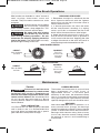
Wire brushes are intended to “clean” structural
steel, castings, sheet metal, stone and
concrete. They are used to remove rust, scale
and paint.
Avoid bouncing and snagging
the wire brush, especially
when working corners, sharp edges etc. This
can cause loss of control and kick-back.
Be aware that wire bristles
are thrown by the brush
even during ordinary operation. Do not
overstress the wires by applying excessive
load to the brush. The wire bristles can easily
penetrate light clothing and/or skin.
BRUSHING PRESSURE
1. Remember, the tips of a wire brush do the
work. Operate the brush with the lightest
pressure so only the tips of the wire come in
contact with the work.
2. If heavier pressures are used, the wires
will be overstressed, resulting in a wiping
action; and if this is continued, the life of the
brush will be shortened due to wire fatigue.
3. Apply the brush to the work in such a way
that as much of the brush face as possible is
in full contact with the work. Applying the side
or edge of the brush to the work will result in
wire breakage and shortened brush life.
!
WARNING
!
WARNING
CORRECT:
Wire tips doing
the work.
INCORRECT:
Excessive
pressure can
cause wire
breakage.
CORRECT:
Wire tips doing
the work.
INCORRECT:
Excessive
pressure can
cause wire
breakage.
WIRE WHEEL BRUSH
WIRE CUP BRUSH
Wire Brush Operations
BM 1609929Y07 10-10:BM 1609929Y07 10-10 1/18/11 10:06 AM Page 16

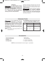
* Type 27 wheel guard
** Type 1A wheel guard
* Lock nut
* Grinding wheel
* Backing flange
* Side handle
* Lock nut wrench
(*= standard equipment)
(**= optional accessories)
Accessories
Extension Cords
NOTE: Not recommended for use with type 11 cup wheels.
If an extension cord is
necessary, a cord with
adequate size conductors that is capable
of carrying the current necessary for your
tool must be used. This will prevent
excessive voltage drop, loss of power or
overheating. Grounded tools must use 3-
wire extension cords that have 3-prong plugs
and receptacles.
NOTE: The smaller the gauge number, the
heav i er the cord.
RECOMMENDED SIZES OF EXTENSION CORDS
120 VOLT ALTERNATING CURRENT TOOLS
!
WARNING
-17-
Tool’s
Ampere
Rating
Cord Size in A.W.G.
Wire Sizes in mm
2
3-6
6-8
8-10
10-12
12-16
18 16 16 14 0.75 0.75 1.5 2.5
18 16 14 12 0.75 1.0 2.5 4.0
18 16 14 12 0.75 1.0 2.5 4.0
16 16 14 12 1.0 2.5 4.0 —
14 12 —— ————
25 50 100 150 15 30 60 120
Cord Length in Feet Cord Length in Meters
Cleaning
To avoid accidents always
dis connect the tool from
the power supply before cleaning or
performing any main tenance. The tool may
be cleaned most effectively with compressed
dry air. Always wear safety gog gles when
cleaning tools with compressed air.
Ventilation openings and switch levers must be
kept clean and free of foreign matter. Do not
at tempt to clean by inserting pointed objects
through openings.
Certain cleaning agents
and sol vents damage
plastic parts. Some of these are: gasoline,
carbon tetrachlo ride, chlo rinated cleaning
solvents, ammonia and house hold detergents
that contain ammonia.
!
WARNING
!
CAUTION
BM 1609929Y07 10-10:BM 1609929Y07 10-10 1/18/11 10:06 AM Page 17

-18-
Avertissements généraux concernant la sécurité des outils électroportatifs
Veuillez lire tous les
avertissements et toutes les
consignes de sécurité. Si l'on n'observe pas ces
avertissements et ces consignes de sécurité, il existe un
risque de choc électrique, d'incendie et/ou de blessures
corporelles graves.
CONSERVEZ TOUS LES AVERTISSEMENTS ET
TOUTES LES CONSIGNES DE SÉCURITÉ POUR
RÉFÉRENCE FUTURE.
Dans les avertissements, le terme « outil électroportatif
» se rapporte à votre outil branché sur le secteur (avec
fil) ou à votre outil alimenté par piles (sans fil).
1) Sécurité du lieu de travail
a) Maintenez le lieu de travail propre et bien éclairé.
Les risques d’accident sont plus élevés quand on
travaille dans un endroit encombré ou sombre.
b) N’utilisez pas d’outils électroportatifs dans des
atmosphères explosives, comme par exemple en
présence de gaz, de poussières ou de liquides
inflammables. Les outils électroportatifs
produisent des étincelles qui risquent d’enflammer
les poussières ou les vapeurs.
c) Éloignez les enfants et les visiteurs quand vous
vous servez d’un outil électroportatif. Vous
risquez une perte de contrôle si on vous distrait.
2) Sécurité électrique
a) Les fiches des outils électroportatifs doivent
correspondre à la prise. Il ne faut absolument
jamais modifier la fiche. N’utilisez pas
d’adaptateur de prise avec des outils
électroportatifs munis d’une fiche de terre. Le
risque de choc électrique est moindre si on utilise
une fiche non modifiée sur une prise qui lui
correspond.
b) Évitez tout contact du corps avec des surfaces
reliées à la terre tels que tuyaux, radiateurs,
gazinières ou réfrigérateurs. Le risque de choc
électrique augmente si votre corps est relié à la
terre.
c) N’exposez pas les outils électroportatifs à la pluie
ou à l’humidité. Si de l’eau pénètre dans un outil
électroportatif, le risque de choc électrique
augmente.
d) Ne maltraitez pas le cordon. Ne vous en servez
jamais pour transporter l’outil électroportatif, pour
le tirer ou pour le débrancher. Éloignez le cordon
de la chaleur, des huiles, des arêtes coupantes ou
des pièces mobiles. Les cordons abîmés ou
emmêlés augmentent les risques de choc électrique.
e) Si vous utilisez un outil électroportatif à
l’extérieur, employez une rallonge conçue pour
l’extérieur. Ces rallonges sont faites pour
l’extérieur et réduisent le risque de choc électrique.
f) S'il est absolument nécessaire d'utiliser l'outil
électroportatif dans un endroit humide, utilisez
une alimentation protégée par un disjoncteur de
fuite de terre (GFCI). L'utilisation d'un disjoncteur
GFCI réduit les risques de choc électrique.
3) Sécurité personnelle
a) Restez concentré, faites attention à ce que vous
faites, et servez-vous de votre bon sens lorsque
vous utilisez un outil électroportatif. N'employez
pas d’outils électroportatifs quand vous êtes
fatigué ou sous l’emprise de drogues, d’alcool ou
de médicaments. Quand on utilise des outils
électroportatifs, il suffit d’un moment d’inattention
pour causer des blessures corporelles graves.
b) Utilisez des équipements de sécurité personnelle.
Portez toujours une protection oculaire. Le port
d'équipements de sécurité tels que des masques
antipoussières, des chaussures de sécurité
antidérapantes, des casques de chantier et des
protecteurs d'oreilles dans des conditions
appropriées réduira le risque de blessure corporelle.
c) Évitez les démarrages intempestifs. Assurez-vous
que l'interrupteur est dans la position arrêt (Off)
avant de brancher l'outil dans une prise de
courant et/ou un bloc-piles, de le ramasser ou de
le transporter. Le transport d'un outil électroportatif
avec le doigt sur la gâchette ou le branchement de
cet outil quand l'interrupteur est en position de
marche (ON) est une invite aux accidents.
d) Enlevez toutes les clés de réglage avant de mettre
l’outil électroportatif en marche. Si on laisse une
clé sur une pièce tournante de l’outil électroportatif,
il y a risque de blessure corporelle.
e) Ne vous penchez pas. Conservez toujours une
bonne assise et un bon équilibre. Ceci vous
permettra de mieux maîtriser l’outil électroportatif
dans des situations inattendues.
f) Habillez-vous de manière appropriée. Ne portez
pas de vêtements amples ou de bijoux. Attachez
les cheveux longs. N’approchez pas les cheveux,
les vêtements ou les gants des pièces en
mouvement. Les vêtements amples, les bijoux ou
les cheveux longs risquent d’être happés par les
pièces en mouvement.
g) Si l’outil est muni de dispositifs permettant le
raccordement d’un système d’aspiration et de
collecte des poussières, assurez-vous que ces
dispositifs sont raccordés et utilisés correctement.
L'utilisation d'un dépoussiéreur peut réduire les
dangers associés à l'accumulation de poussière.
4) Utilisation et entretien des outils électroportatifs
a) Ne forcez pas sur l’outil électroportatif. Utilisez
l’outil électroportatif qui convient à la tâche à
effectuer. L’outil qui convient à la tâche fait un
AVERTISSEMENT
!
BM 1609929Y07 10-10:BM 1609929Y07 10-10 1/18/11 10:06 AM Page 18

-19-
meilleur travail et est plus sûr à la vitesse pour
lequel il a été conçu.
b) Ne vous servez pas de l’outil électroportatif si son
interrupteur ne parvient pas à le mettre en marche
ou à l’arrêter. Tout outil électroportatif qui ne peut
pas être commandé par son interrupteur est
dangereux et doit être réparé.
c) Débranchez la fiche de la prise ou enlevez le bloc-
pile de l’outil électroportatif avant tout réglage,
changement d’accessoires ou avant de ranger
l’outil électroportatif. De telles mesures de sécurité
préventive réduisent le risque de démarrage
intempestif de l’outil électroportatif.
d) Rangez les outils électroportatifs dont vous ne
vous servez pas hors de portée des enfants et ne
permettez pas à des personnes qui ne connaissent
pas l’outil électroportatif ou qui ignorent ces
consignes de s’en servir. Les outils électroportatifs
sont dangereux dans les mains d’utilisateurs
inexpérimentés.
e) Entretenez les outils électroportatifs. Vérifiez que
les pièces mobiles sont alignées correctement et
ne coincent pas. Vérifiez qu’il n’y a pas de pièces
cassées ou d’autre circonstance qui risquent
d’affecter le fonctionnement de l’outil
électroportatif. Si l’outil est abîmé, faites-le
réparer avant de l’utiliser. De nombreux accidents
sont causés par des outils électroportatifs mal
entretenus.
f) Maintenez les outils coupants affûtés et propres.
Les outils coupants entretenus correctement et
dotés de bords tranchants affûtés sont moins
susceptibles de coincer et sont plus faciles à
maîtriser.
g) Utilisez l'outil électroportatif, les accessoires et
les embouts d'outil, etc. conformément à ces
instructions, en tenant compte des conditions de
travail et des travaux à réaliser. L'emploi d’outils
électroportatifs pour des tâches différentes de celles
pour lesquelles ils ont été prévus peut résulter en
une situation dangereuse.
Entretien
a) Faites réparer votre outil électroportatif par un
agent de service qualifié n’utilisant que des
pièces de rechange identiques. Ceci assure que la
sécurité de l’outil électroportatif est préservée.
Avertissements spécifiques à la sécurité des outils électroportatifs
Avertissements habituels concernant la sécurité des
opérations de rectification, de ponçage, de brossage
métallique et de tronçonnage à la meule abrasive :
a) Cet outil électroportatif a été conçu pour
fonctionner comme un outil de rectification, de
ponçage, de brossage métallique ou de
tronçonnage. Veuillez lire toute la documentation
relative à la sécurité qui a été fournie avec cet
outil électroportatif, notamment, les
avertissements, les consignes, les illustrations et
les spécifications. Si l'on n'observe pas toutes les
consignes indiquées ci-dessous, il existe un risque
de choc électrique, d'incendie et/ou de blessures
corporelles graves.
b) Cet outil électroportatif n'est pas recommandé
pour le polissage. L'usage de l'outil au cours de
travaux pour lesquels il n'a pas été conçu risque de
présenter un danger et de causer des blessures
corporelles.
c) N'utilisez pas d'accessoires qui n'ont pas été
spécifiquement conçus et recommandés par le
fabricant de l'outil. Le simple fait qu'un accessoire
puisse être attaché à votre outil électroportatif ne
garantit pas un fonctionnement sans danger.
d) La vitesse nominale de l'accessoire doit être au
moins égale à la vitesse maximum indiquée sur
l'outil électroportatif. Les accessoires que l'on fait
tourner à une vitesse supérieure à leur VITESSE
NOMINALE peuvent se casser et voler en éclats.
e) Le diamètre externe et l'épaisseur de votre
accessoire doivent être dans les limites de
capacité de votre outil électroportatif. Des
accessoires de la mauvaise taille ne peuvent pas être
adéquatement protégés ou contrôlés.
f) Les arbres des meules, des brides, des disques
d'appui ou de tous les autres accessoires doivent
être d'une taille qui leur permet d'être ajustés
correctement sur la broche de l'outil
électroportatif. Les accessoires qui ont des orifices
d'arbre n'étant pas compatibles avec la quincaillerie
de montage de l'outil électroportatif seront
déséquilibrés, vibreront de manière excessive et
risquent de causer une perte de contrôle.
g) N'utilisez pas d'accessoires endommagés.
Inspectez vos accessoires avant chaque utilisation
: vérifiez par exemple que votre meule abrasive
n'est ni fêlée, ni ébréchée, que votre disque
d'appui n'est ni fêlé, ni déchiré, ni trop usé et que
votre brosse métallique ne contient pas de fils
cassés ou détachés. Si vous laissez tomber l'outil
ou l'accessoire, vérifiez que ce dernier n'est pas
endommagé ou remplacez-le par un accessoire en
bon état. Après l'inspection et l'installation d'un
accessoire, tenez-vous à distance du plan de
l'accessoire en mouvement et demandez à toute
personne présente de faire de même, et faites
fonctionner l'outil à sa vitesse à vide maximale
pendant une minute. Si un accessoire est
endommagé, il se cassera habituellement en
plusieurs morceaux pendant cette période de test.
BM 1609929Y07 10-10:BM 1609929Y07 10-10 1/18/11 10:06 AM Page 19

-20-
h) Portez des équipements de protection personnelle.
Suivant le travail effectué, portez un masque de
protection, des lunettes à coques ou des lunettes
de sécurité. S'il y a lieu, portez un masque
antipoussières, des dispositifs de protection de
l'ouïe, des gants et un tablier d'atelier capable
d'arrêter des petits fragments abrasifs ou des
fragments de la pièce. Les dispositifs de protection
des yeux doivent pouvoir arrêter des débris volants
produits par diverses opérations. Le masque
antipoussières ou le respirateur doit être capable de
filtrer des particules générées par votre travail. Une
exposition prolongée à un bruit de haute intensité
peut entraîner une perte de l'ouïe.
i) Gardez toute personne présente à une distance
sûre de l'aire de travail. Toute personne qui entre
dans l'aire de travail doit porter des équipements
de protection personnelle. Des fragments d'une
pièce ou d'un accessoire peuvent être projetés et
causer des blessures au-delà de l'aire d'opération
immédiate.
j) Tenez l'outil électroportatif exclusivement au
niveau de ses surfaces de préhension isolées
quand vous réalisez une opération au cours de
laquelle l'accessoire de coupe risque d'entrer en
contact avec des fils électriques dissimulés ou
avec son propre cordon d'alimentation. Quand un
accessoire de coupe entre en contact avec un fil «
sous tension », cela peut mettre des parties
métalliques exposées de l'outil électroportatif « sous
tension » et électrocuter l'utilisateur.
k) Positionnez le cordon hors de la trajectoire de
l'accessoire en mouvement. Si vous perdez
contrôle de l'outil, le cordon d'alimentation risque
d'être coupé ou de s'accrocher et votre main ou
votre bras risque d'être tiré jusqu'à ce qu'il entre en
contact avec l'accessoire en mouvement.
l) Ne posez jamais l'outil électroportatif tant que
l'accessoire n'a pas complètement cessé de
tourner. L'accessoire en mouvement risque
d'accrocher la surface sur laquelle il est posé et de
vous faire perdre contrôle de l'outil.
m) Ne laissez pas l'outil électroportatif en marche
quand vous le portez sur le côté. Un contact
accidentel avec l'accessoire en mouvement risquerait
d'accrocher vos vêtements et d'attirer l'accessoire
vers votre corps.
n) Nettoyez régulièrement les prises d'air de l'outil
électroportatif. Le ventilateur du moteur attirera de
la poussière à l'intérieur du boîtier de l'outil et une
accumulation excessive de poudre métallique risque
de causer des dangers électriques.
o) Ne faites pas fonctionner l'outil électroportatif à
proximité de matériaux inflammables. Des
étincelles pourraient enflammer ces matériaux.
p) N'utilisez pas d'accessoires qui exigent des
liquides de refroidissement. L'utilisation d'eau ou
d'autres liquides de refroidissement peut entraîner
une électrocution ou un choc électrique.
Avertissements sur les rebonds et effets associés
L'effet de rebond est une réaction soudaine au
pincement ou à l'accrochage d'une meule, d'un disque
d'appui, d'une brosse ou de tout autre accessoire
pivotant. Un tel pincement ou accrochage fait
rapidement caler l'accessoire en mouvement, ce qui
force l'outil électroportatif hors de contrôle à aller dans la
direction opposée à celle de la rotation de l'accessoire à
l'emplacement du blocage.
Par exemple, si une meule abrasive est accrochée ou
pincée par la pièce, le bord de la meule à l'emplacement
du pinçage peut creuser la surface du matériau et forcer
la meule à se « hisser » sur la pièce ou à être éjectée. La
meule peut alors sauter soit en direction de l'utilisateur,
soit dans la direction opposée, en fonction de la direction
du mouvement de la meule à l'emplacement du
pincement. Les meules abrasives peuvent également se
briser dans de telles conditions.
Les rebonds résultent d'une mauvaise utilisation de
l'outil électroportatif et/ou de procédures ou de
conditions d'utilisation incorrectes, et ils peuvent être
évités en prenant les précautions nécessaires indiquées
ci-dessous :
a) Maintenez une prise ferme sur l'outil
électroportatif et positionnez votre bras et le reste
de votre corps de façon à vous permettre de
résister aux forces de rebond. Utilisez toujours la
poignée auxiliaire, quand elle vous a été fournie,
pour un contrôle maximum du rebond ou de la
réaction de couple qui se produit pendant la mise
en marche de l'outil. L'utilisateur peut contrôler les
réactions de couple ou les forces de rebond en
prenant les précautions nécessaires.
b) Ne placez jamais votre main à proximité de
l'accessoire en mouvement. L'accessoire risquerait
de rebondir sur votre main.
c) Ne vous placez jamais dans la zone où l'outil
électroportatif se dirigerait si un rebond se
produisait. L'effet de rebond projetterait l'outil dans
la direction opposée à celle du mouvement de la
meule à l'emplacement de l'accrochage.
d) Faites particulièrement attention quand vous
travaillez des coins ou des arêtes tranchantes, etc.
Évitez de faire rebondir ou d'accrocher
l'accessoire. Les coins, les arêtes tranchantes et les
rebondissements ont tendance à faire accrocher
l'accessoire en mouvement et à entraîner une perte
de contrôle ou un rebond.
e) Ne fixez pas une lame à sculpter le bois de chaîne
coupante ou une lame de scie dentée sur l'outil. De
telles lames causent fréquemment des rebonds et
des pertes de contrôle.
BM 1609929Y07 10-10:BM 1609929Y07 10-10 1/18/11 10:06 AM Page 20
La page charge ...
La page charge ...
La page charge ...
La page charge ...
La page charge ...
La page charge ...
La page charge ...
La page charge ...
La page charge ...
La page charge ...
La page charge ...
La page charge ...
La page charge ...
La page charge ...
La page charge ...
La page charge ...
La page charge ...
La page charge ...
La page charge ...
La page charge ...
La page charge ...
La page charge ...
La page charge ...
La page charge ...
La page charge ...
La page charge ...
La page charge ...
La page charge ...
La page charge ...
La page charge ...
La page charge ...
La page charge ...
-
 1
1
-
 2
2
-
 3
3
-
 4
4
-
 5
5
-
 6
6
-
 7
7
-
 8
8
-
 9
9
-
 10
10
-
 11
11
-
 12
12
-
 13
13
-
 14
14
-
 15
15
-
 16
16
-
 17
17
-
 18
18
-
 19
19
-
 20
20
-
 21
21
-
 22
22
-
 23
23
-
 24
24
-
 25
25
-
 26
26
-
 27
27
-
 28
28
-
 29
29
-
 30
30
-
 31
31
-
 32
32
-
 33
33
-
 34
34
-
 35
35
-
 36
36
-
 37
37
-
 38
38
-
 39
39
-
 40
40
-
 41
41
-
 42
42
-
 43
43
-
 44
44
-
 45
45
-
 46
46
-
 47
47
-
 48
48
-
 49
49
-
 50
50
-
 51
51
-
 52
52


Bosch 1821 Manuel utilisateur
- Catégorie
- Outils électroportatifs
- Taper
- Manuel utilisateur
dans d''autres langues
- English: Bosch 1821 User manual
- español: Bosch 1821 Manual de usuario
Documents connexes
-
Bosch GWS8-45 Manuel utilisateur
-
Bosch Power Tools 1380SLIM-2P Manuel utilisateur
-
Skil 9295-02 Manuel utilisateur
-
Bosch CAG180-01 Mode d'emploi
-
-
Bosch Power Tools 1853-6 Manuel utilisateur
-
-
Bosch Power Tools 1994-6 Manuel utilisateur
-
-
Bosch Power Tools 1873-8F Manuel utilisateur
Autres documents
-
-
Skil 9781MA Manuel utilisateur
-
-
 Total TG1252306 Le manuel du propriétaire
-
 Total TP1141806 Le manuel du propriétaire
-
-
Skil 9296 Le manuel du propriétaire
-
Milwaukee 6117-33S Manuel utilisateur
-
Milwaukee 6146-30 Manuel utilisateur

