Signature Kitchen Suite SKSFD3604P Guide d'installation
- Taper
- Guide d'installation

Integrated Refrigeration Installation Guide
BUILT-IN REFRIGERATION
SKSFD3604P
ENGLISH FRANÇAIS ESPAÑOL
Copyright © 2018 - 2020 SIGNATURE KITCHEN SUITE. All Rights Reserved.
www.signaturekitchensuite.com (USA)
www.signaturekitchensuite.ca (CANADA)
MFL67410815_Rev.05

2
Table of Contents
SAFETY INSTRUCTIONS ......................... 3
Before Installation ................................. 6
Choosing the Install Location ......................... 6
SKSFD3604P – 36” INTEGRATED FRENCH
DOOR REFRIGERATOR ................................. 9
Required Accessories and Tools ................... 13
Installation ........................................... 14
Unpacking ...................................................... 14
Moving the Appliance .................................... 15
Special Circumstances .................................... 15
Product Dimensions ....................................... 16
A
Installing the Anti-tip Brackets ........................ 17
Protecting Edges of Enclosure ........................ 18
Installing Appliance in Enclosure ................... 19
B
Aligning and Leveling the Appliance .............. 20
Attaching the Appliance to the Enclosure ........ 22
Attaching the Toe Kick Panel .......................... 23
Loading the Appliance Door .......................... 24
C
Installing Door Panels ................................... 25
Adjusting Door Panels ................................... 26
Installing Door Trim ...................................... 26
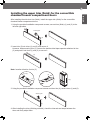
Installing the upper trim (finish) for
the convertible chamber/freezer
compartment doors ......................................... 27
Attaching Air Separator .................................. 29
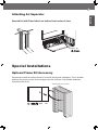
◆ Special Installations
Optional Frame Kit Accessory .......................... 29
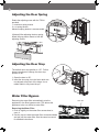
Adjusting the Door Spring ............................. 30
Adjusting the Door Stop ................................ 30
Water Filter Bypass ....................................... 30
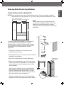
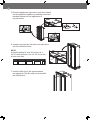
Side-by-Side Flush Installation .......................... 31
Precautions for Panel Installation ...................... 33
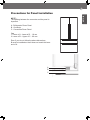
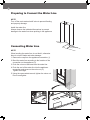
Preparing to Connect the Water Line .............. 34
Connecting the Water Line ............................ 34
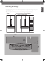
Attaching the Badge ...................................... 35

3
ENGLISH
SAFETY INSTRUCTIONS
WARNING
TIP-OVER HAZARD
Use two or more people to move and install the refrigerator.
To prevent the refrigerator from tipping over, install anti-tip brackets
(provided). Failure to follow the refrigerator installation instructions
can result in serious injury or death.
WARNING You may be killed or seriously injured if you don’t follow instructions.
WARNING To reduce the risk of re, electric shock, or personal injury when using
the product, basic safety precautions should be followed, including the
following. Read all instructions before using this appliance.
CAUTION Indicates an imminently hazardous situation which, if not avoided, may
result in minor or moderate injury, or product damage.
WARNING This product contains chemicals known to the State of California to
cause cancer and birth defects or other reproductive harm.
Wash hands after handling.
IMPORTANT SAFETY INSTRUCTIONS
This guide contains many important safety messages.
Always read and obey all safety messages.
This is the safety alert symbol. It alerts you to safety messages that inform you of hazards
that can kill or hurt you or others or cause damage to the product.
All safety messages will be preceded by the safety alert symbol and the hazard signal word
WARNING, or CAUTION. These words mean:
All safety messages will identify the hazard, tell you how to reduce the chance of injury, and
tell you what can happen if the instructions are not followed.
Installation
• These products are not designed to be used as freestanding units. Doing so will result in a
risk of tipover, personal injury, and product or property damage.
• Do not install the refrigerator near a gas stove, water heater or other source of ignition that
may possibly leak gas. Do not install product in direct sunlight. Install the product in a well-
ventilated area.
• Ensure that enclosure dimensions allow for sufcient air circulation at the sides and back of
the product. Do not block the front air inlet. Failure to follow these instructions may cause
product malfunction.
• Enclosure must be constructed of materials which are strong enough to avoid damage
during installation and frequent use.

4
• Cabinet materials must be able to withstand the heat and humidity produced during product
operation and use without twisting or deforming.
• Install the product on a rm, level surface that can support the weight of the product without
bending. The product must be level both horizontally and vertically.
• Keep children away from area during installation.
• Do not use an extension cord or power strip with this product.
• Do not install the refrigerator in a damp location or where it will be exposed to running water.
Deterioration of the insulation on electrical parts may result, causing risk of electric shock.
• Connect to potable water only. Non-potable water can cause health risks.
• If connected to a circuit protected by fuses, use time delay fuse.
Electrical Connection
Use a dedicated outlet.
• Plugging several devices into one outlet may cause a re.
Plug in the power plug with the power cord facing downward.
Failure to do so could damage the plug or cord, resulting in re or electric shock.
When installing or moving the refrigerator, be careful not to roll over or damage the
power cord. Do not squeeze or crush the cord or plug when pushing the refrigerator in.
Doing so could result in re or electric shock.
Do not allow the power cord to be bent, crushed, or damaged. Do not run the power
cord under heavy objects like furniture, other appliances, or through high-trafc areas.
Doing so may damage the power cord and result in re or electric shock.
Do not extend or modify the length of the power cord.
Use only an exact factory replacement part to avoid electrical issues, re, or electric shock.
Turn off the power before cleaning or moving the refrigerator.
• Failure to do so may cause electric shock or injury.
• Press the POWER button for 3 seconds to turn off the power at display panel.
Do not pull out the cord or touch the power plug with wet hands.
Doing so may cause electric shock or injury.
Remove water or dust from the power plug and insert it securely into the wall socket.
Dust, water, or a loose connection may cause a re or electric shock.
Do not unplug the refrigerator by pulling on the cord.
Doing so may cause electric shock or short circuit resulting in a re.
Do not use the power cord or the power plug if it is damaged or if the outlet is damaged.
Doing so may cause electric shock or short circuit resulting in a re.
Wait for 5 minutes or longer when reconnecting the plug or turning the power back on.
Give the compressor time to cycle before restarting.

5
ENGLISH
General
These installation instructions are intended for use by qualied installers. All connections for water,
electrical power and grounding must comply with local codes and ordinances and be made by
licensed personnel when required. In the absence of a local code:
✓ In the U.S.A., in accordance with the National Electric Code, ANSI/NFPA70 – latest edition/
State and Municipal codes and/or local codes.
✓ In Canada, in accordance with the Canadian Electric Code C22.1 – latest edition/Provincial and
Municipal codes and/or local codes.
French Door Refrigerator 36” approx. 532 lbs / 241 kg
CAUTION
Do not remove the cover of the automatic ice dispenser.
The internal mechanism of the icemaker can cause injury if handled.
Do not stick your hands under the refrigerator.
Sharp edges, fans, and wires may cause an injury
Save these instructions for the local inspector's use.
Observe all governing codes and ordinances.
Installer: Leave these instructions with the consumer.
Consumer: Keep these instructions with the owner's manual for future reference.
If the power supply cord is damaged, it must be replaced by the manufacturer or its
service agent or a similarly qualied person in order to avoid a hazard.

6
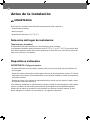
Before Installation
Choosing the Install Location
Anti-tip Devices
WARNING
Do not store or install the appliance where it will be exposed to:
• outside weather
• water damage
• temperatures under 32°F (0°C)
Temperature and Humidity
The appliance should be installed in a dry, well ventilated area.
The ambient temperature should stay between 55 °F(13 °C) and 110 °F (43 °C), to avoid
malfunctions.
Do not install product where it will be exposed to direct sunlight or near a heat source, such as an
oven or radiator.
WARNING: Tip Hazard
• The appliance is very heavy and may tip over if the door is opened before the appliance is
securely installed.
• Install the supplied anti-tip brackets to prevent the appliance from tipping.The safest method of
installing the appliance in a stable position is to use the supplied anti-tip devices.
• Do not open the appliance door or drawers unless it is still on the pallet or the anti-tip brackets
are engaged.
If the enclosure is sturdy enough, attaching the appliance to the upper and side walls of the
enclosure may provide additional stability, as long as the enclosure is rmly connected to the back
wall. If in doubt, contact an architect or structural engineer.

7
ENGLISH
Enclosure
•The panel above the appliance must be made from a solid material (not MDF) that is at
least 5/8" (16 mm) thick.
•The side walls of the cavity or enclosure must be ush.
•The front 4 inches (100 mm) of the interior surface (furniture return) will be visible when
doors are open. Make sure this area is nished to at least 4 inches deep.
•Follow the specications for the installation enclosure to ensure a trouble free installation.
•Above all, the enclosure cannot be out of square. Use a spirit level or measure the
diagonals of the opening to make sure corners are square.
•The appliance is attached at the sides and the top to either the enclosure or to adjacent
cabinets. Make sure the enclosure or the adjacent cabinets are securely connected to the
oor or wall structures.
Floor
WARNING
•The oor in the installation area must be rm, level, and rigid for safe installation and best
performance.
•Do not install the appliance on a platform or raised structure.
•The structure underneath the appliance must be able to support the weight of the
appliance without tilting or exing.
•For best performance and to avoid leakage, level the appliance.
Electrical Requirements
WARNING
Electrical Shock Hazard
✓ Plug into a grounded 3 prong outlet.
✓ Do not remove ground prong.
✓ Do not use an adapter.
✓ Do not use an extension cord.
Failure to follow these instructions can result in death, re, or electrical shock.
Follow all state and local codes or NEC.
The appliance comes with a UL listed 3 wire power supply cord.
The appliance requires a 3-wire receptacle.
The receptacle must be installed by a licensed electrician only.

8
Grounding
This appliance must be grounded. In the event of a malfunction or breakdown, grounding will
reduce the risk of electric shock by providing a path of least resistance for the electric current.
WARNING
Improper connection of the equipment grounding conductor may result in electric shock. Have
the appliance checked by a qualied electrician or service technician if you are in doubt as to
whether the appliance has been properly grounded.
NOTE
Some local regulations may require a separate ground. In such cases, the required ground
wire, clamp and screw are available as a separate accessory and must be purchased
separately.
Never ground the appliance to plastic plumbing lines, gas lines or water pipes.
Water Connection
CAUTION
•Connect the appliance to potable water only.
•A cold water connection is required for operation of the automatic ice maker. The water
pressure must be between 20 and 120 psi. (138 - 827 kPa).
•The installation must comply with local plumbing regulations.
•A separate shut-off valve must be installed for the appliance water connection.
•Do not use a self-piercing valve.
•Do not install the shutoff valve for the water behind the appliance. The shutoff valve must be
easily accessible.
•Install the water connection in the area shown in the diagram under Dimensions and
Clearances. The water supply line can be located on the right side, on the left side, or in the
oor. The maximum outer diameter of the supply line (without ttings) is 3/8" (9.5 mm).

9
ENGLISH
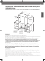
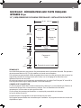
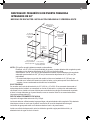
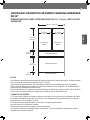
SKSFD3604P – 36” INTEGRATED FRENCH DOOR REFRIGERATOR
NOTE
Refrigerator can be installed ush or proud.
Flush – With a 25" (635 mm) cutout depth, the front face of the freezer ts ush with 25" (635 mm)
depth adjacent cabinets.
Proud – With a 24" (610 mm) depth cutout, the front face of the freezer extends approximately 3/4"
(19 mm) beyond 24" (610 mm) depth adjacent cabinets.
• A minimum 4" (102 mm) nished return that matches the cabinet exterior is recommended on all
sides and the top of the cutout opening. The shaded area will be visible after installation.
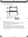
ELECTRICAL
A 115V, 60Hz, 15 or 20 amp power supply is required. An individual properly grounded branch
circuit or circuit breaker must be used in case of requiring disconnect after installation. Install a
properly grounded 3-prong electrical
receptacle recessed into the back wall. Electrical must be located on rear wall as shown.
Note: GFI (ground fault interrupter) is not recommended.
WATER LINE
A cold water supply is required for automatic icemaker operation.
The water pressure must be between 20 and 120 psi.
Tubing should be long enough to extend to the front of the freezer. Allow enough tubing to
accommodate a bend leading into the water line connection.
Water line can enter an opening through the oor or back wall.
Install a shut-off valve between the icemaker water valve and the cold water supply in the home.
CUTOUT DIMENSIONS – FLUSH OR PROUD INSTALLATION
1 3/8" (35mm)
Electrical location
is not available
1 3/8" (35mm)
Electrical location
is not available
36" (914 mm)
84"
(2134 mm)
5"
(127 mm)
electrical
location
4"
(102 mm)
water
location
4"
(102 mm)
finished
return*
25"(635 mm)
min. depth
flush install
24" (610 mm)
min. depth
proud install
finished width

10
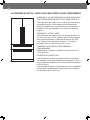
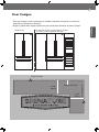
NOTE
Door Swing Clearances
The installation must allow for clearances to adjacent walls or cabinets. This freezer is equipped with
a 2-position door stop.
The factory-set 115° door swing can be adjusted to 90° if clearance to adjacent cabinets or walls is
restricted.
Door Handle Clearances
The door handle depth must be added to the dimension where noted to determine the total
clearance required from adjacent cabinets or walls. This clearance will vary depending on the custom
handle used. When using Signature Kitchen Suite handles or the Signature Kitchen Suite stainless
steel door panel kit with handles (optional accessories), the door handle clearance with the door
open 115° is 12" (305mm).
INSTALLATION CLEARANCES
TOP VIEW
90°
115°
9 1/4"*
(235 mm)
9 1/4"*
(235 mm)
24"
(610 mm)
20 15/16"
(530 mm)
36" (914 mm)
1/8"
(3mm)
min.
17 13/16"
(452 mm)
17 13/16"
(452 mm)
1/8"
(3mm)
min.
90° 115°
3/4"
(19 mm)**
Door handle must be added to this dimension.
*
** Varies depending on the thickness
of the custom cabinet panel.
3/4" (19 mm) is relevant when
using the Stainless Steel Door
Panel Kit (optional accessory).
35 3/4"(908 mm)

11
ENGLISH
SKSFD3604P – 36” INTEGRATED FRENCH DOOR REFRIGERATOR
NOTES
Trimmed units are designed to be customized with decorative panels. Field-installed 3/4" (19 mm)
custom door panels are required.
For custom panels: Use templates provided with units to pre-drill holes for mounting panel brackets
(provided with unit). Adjustment screws and instructions also provided with units.
The maximum total weight for custom panels for the 36" French Door model is 88 lb. For maximum
weights for each panel, see the spec sheet.
DESIGN TIPS
4" (102 mm) will be visible on the interior sides of the cutout. It is recommended that the
interior of the enclosure be nished to match the exterior. For retrot/replacement installations,
the optional frame kit may be used.
If using custom panels, a custom toe kick is required.
The bottom of the case is unnished.
Door Handles: Handles are not included with the units.
Custom handles are required for installation. Brushed aluminum handles are available as an optional
accessory.
3/4" (19 MM) CUSTOM PANEL DIMENSIONS – FLUSH INSTALLATION
35 3/4" (908 mm)
49 3/8"
(1254 mm)
9 3/16"
(233 mm)
4"
(102 mm)
21"
(533.5 mm)
17 13/16"
(452 mm)
17 13/16"
(452 mm)
Door Panel Door Panel
Door Panel
Toe-kick Panel
Door Panel

12
SKSPK360FS – STAINLESS STEEL PANEL KIT FOR 36”
FRENCH DOOR REFRIGERATOR
This unit can be installed with an optional stainless steel panel
kit. The kit includes two fresh food door panels, one convertible
drawer panel, one freezer drawer panel, one toe kick, and four
handles.
SKSFK800CS – FRAME KIT
This unit can be installed in a 24" (610 mm) deep cutout with
an optional frame kit. The kit includes two 80" (2032 mm)
brushed aluminum side trim pieces. Each trim piece is 5" (127
mm) deep with a 1/8" (3 mm) front face.
HANDLES FOR USE WITH CUSTOM PANELS
SKSHK310HS – 31 11/16“ (805 mm) Medium Brushed
Aluminum Handle
DESIGN TIPS
The stainless steel panel kit may be used in a ush 25" (635
mm) cutout depth installation or in a proud 24" (610 mm) cutout
depth installation.
The optional frame kit is recommended for retrot/replacement
installations where the existing cutout is 24" (610 mm) deep.
OPTIONAL ACCESSORIES – FLUSH OR PROUD INSTALLATION

13
ENGLISH
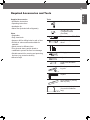
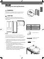
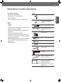
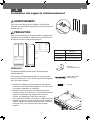
Required Accessories and Tools
Supplied Accessories
•
Installation instructions
•
Operating instructions
•
Installation kit
• Water lter (included with refrigerator)
Other
•
Stepladder
•
Dolly, hand truck
•
Hammer drill for drilling holes in wall or oor.
•
Drill bits in various sizes and suitable for
materials
•
Wood screws in different sizes
•
Thin plywood sheet, particle board or
cardboard to protect the oor from damage
•
Suitable material for covering and protecting
furniture (e.g. protective sheets)
•
Adhesive tape
Tools
Cordiess screwdriver
Torx bit T20, T30
+ magnetic holder
(Provided)
Torx screwdriver T20, T30
6/16"(10 mm) hex nut
driver
Various drill bits
Multigrip pliers
Adjustable wrench
Cutter with adustable
blade
Metal tape measure, fold-
ing rule
Square
Level, length 2' (60 cm)
and 4'(1.2 m)
saw to cut top trim pieces
(for retrot installation
only)

14
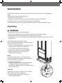
Installation
The following installation instructions describe the installation steps for various appliance
types:
•Refrigerator units with water dispenser
•Freezer units with ice maker
•Integrated refrigerator and freezer units with water dispenser and icemaker
The diagrams may be a general representation of your appliance.
Particular reference is made to special installation steps for individual appliance types.
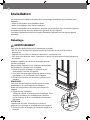
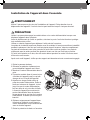
Unpacking
WARNING
To avoid serious injury or product damage:
•DO NOT open appliance door unless the product is secured against tipping.
•The appliance is very heavy and is prone to tipping if not secured.
•To avoid injury, use 2 or more people and proper lifting techniques when lifting or moving
the appliance.
Check appliance for damage in transit.
Do not install the appliance if it is visibly damaged.
If in doubt, contact your dealer.
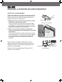
1. Remove the packaging carton, being careful not
to damage the surface of the appliance.
2. To avoid oor damage, place packaging
cardboard or plywood under the appliance.
3. Remove accessories on the sides and
underneath the appliance.
NOTE:
To avoid damaging parts, do not remove the
protective shipping materials inside the appliance
until the installation is complete.
4. Installation Preparation
Unpack installation materials and accessories.
To simplify installation, the packages are
identied with labels A, B and C corresponding to
the manual sections.
CAUTION:
Appliance is very heavy. Use two or more people
when lifting or moving the appliance.
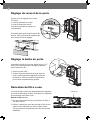
5. Remove shipping brackets (a) and lift the
appliance off the pallet.
aa
a

15
ENGLISH
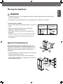
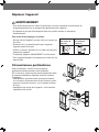
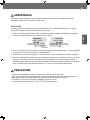
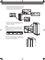
Moving the Appliance
WARNING
• To avoid injury, use 2 or more people and observe proper lifting techniques when lifting or
moving the appliance.
• If the appliance cannot be transported in an upright position, transport it horizontally.
A
B
C
To avoid product damage:
•Do not tilt the appliance toward the sides or lay it on its
sides.
•Make sure there is sufcient room to stand the
appliance upright before doing so.
•Use a dolly, lift truck or hand cart to transport the
appliance.
•Transport from the rear side of the appliance ONLY.
•Secure the appliance during transport to prevent it
from tipping.
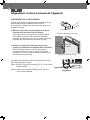
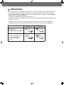
Special Circumstances
Before proceeding with your installation, check if any
of the following special circumstances apply to your
installation. If so, follow the relevant instructions in the
Special Installations section before continuing the
installation.
•Retrot installation in existing enclosure: see Optional
Frame Kit Accessory section.
•Reversing door swing: see Door Reversal section.
•Side-by-Side installation of 2 appliances: see Side-by-
Side Installation section.
Raise up via
appliance rear
Do not raise up
from appliance
side

16
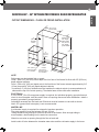
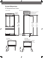
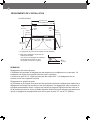
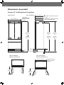
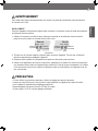
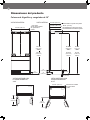
Product Dimensions
24 3/4"*
22"***
23 7/8"**
(629 mm)
(558 mm)
(607 mm)
4"
5"
(127 mm)
(102 mm)
4"
(102 mm)
Depth with 3/4" (19 mm) door pane
l
Depth with door (no panel)
Unit depth without door
*
**
***
9"
(229 mm)
3/4" (19 mm)
80 9/16"
(2046 mm)
min.
81 9/16"
(2072 mm)
max.
21 7/8"
(556 mm)
TOP VIEW
DOOR OPEN 115˚
SIDE VIEW
FRONT VIEW
TOP VIEW
DOOR OPEN 90˚
35 3/4" (908 mm)
83 1/2"
(2121 mm)
min.
84 1/2"
(2146 mm)
max.
Unit width
Unit width
Without
door panel
without
door panel
20 1/2"
(520 mm)
35 3/4" (908 mm)
83 1/5"
(2113 mm)
min.
84 1/5"
(2139 mm)
max.
36" Refrigerator/Freezer Column

17
ENGLISH
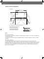
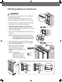
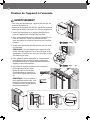
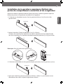
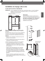
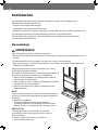
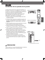
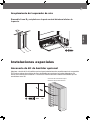
Installing the Anti-tip Brackets
NOTE:
2 anti-tip-brackets are required for each appliance.
The anti-tip-brackets must overlap a minimum of 2 1/8"
(54 mm) over the appliance to secure the appliance.
1. Install the anti-tip brackets at the rear of the enclosure,
with the base of the brackets 3 5/16” from the top of
the enclosure.
2. Make sure the anti-tip brackets are securely attached
to a stud or other weight-bearing structure.
Do not attach brackets to drywall, cinderblock, or
uncured concrete.
To ensure safety, at least one bracket must be
attached to a stud. Attach brackets to studs wherever
possible within the enclosure. Use a minimum of 3
screws or bolts to attach each bracket.
WARNING
To avoid injury or damage, check for electrical wires or
plumbing in walls before drilling or installing screws.
CAUTION
To avoid injury, observe all safety practices during
installation, including wearing safety glasses and other
safety apparel.
C
B
A
80 9/16"
(2046 mm)
min.
81 9/16"
(2072 mm)
max.
>21/8"
(54 mm)
A
36" Unit
A (Width) 35 3/4" (908mm)
B (Depth) 23 7/8"(607mm)
C (Height) 83 ½"(2121mm) min.
Anti-tip brackets (2)
Concrete / Wood wall
5X45 6X (Hex)
6x30 6X

18
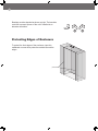
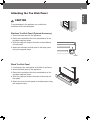
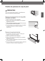
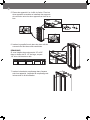
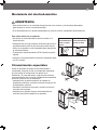
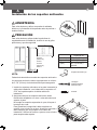
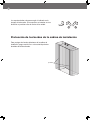
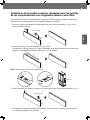
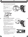
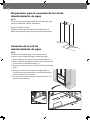
Protecting Edges of Enclosure
To protect the front edges of the enclosure, tape thin
cardboard or some other protective material around the
edges.
protection
2 3/8"
(60 mm)
3 3/4"
(95 mm)
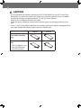
Brackets must be attached as shown at right. The brackets
could fail to prevent tipover of the unit if installed in an
alternate orientation.
protection
2 3/8"
(60 mm)
3 3/4"
(95 mm)

19
ENGLISH
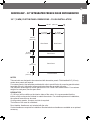
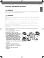
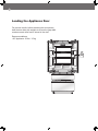
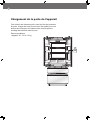
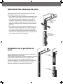
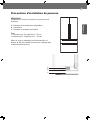
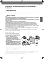
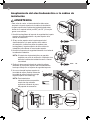
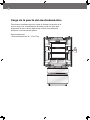
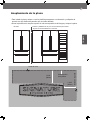
Installing Appliance in Enclosure
1. Remove the base panel.
2. Retract the leveling legs so the appliance
can be wheeled forward.
3. Plug the power cord into the outlet.
4. Push the water line through the hole at the
rear of the appliance until it emerges from
the hole at the front of the appliance.
5. Tie a long string around the middle of the
power cord. Feed the string over the top of
the appliance, pull it until the power cord
is held high off the ground, then tape the
string to the front of the appliance to hold
the power cord off the ground. Do not pinch
or strain the power cord. Make sure it is still
plugged in.
6. Carefully move the appliance into the
enclosure, making sure not to pinch the
power cord or water line under or behind the
appliance.
7. Remove the edge protection on the
enclosure.
CAUTION
Take care to avoid damaging the water line or power cord when moving the appliance into the
enclosure.
Before moving the unit into position, secure the door/ drawers closed and protect any nished
ooring.
Use an appliance dolly to move the unit near the opening.
The front leveling legs are extended below the front rollers to improve stability during
placement. Once the unit is placed in front of the opening, completely retract the front leveling
legs to allow the unit to be rolled into position. Front and rear leveling legs can be adjusted
from the front once the unit is positioned.
If the unit has been on its back it must stand upright for a minimum of 24 hours before turning
on the power.
After the appliance is rolled into position, verify that the anti-tip brackets are properly engaged.
WARNING
Use 2 or more people when installing the appliance. Take care when moving the appliance. It
is very heavy and prone to tipping when not secured.
4
5
6
3
2
1
5

20
B
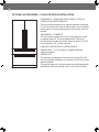
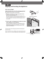
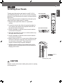
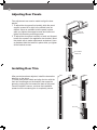
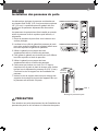
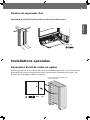
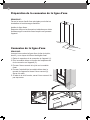
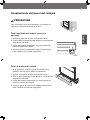
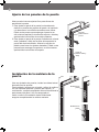
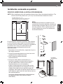
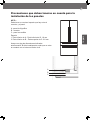
Aligning and Leveling the Appliance
DEPTH ADJUSTMENT
Adjust the depth of the unit in the enclosure so the door
panels will t ush with the surrounding cabinetry. Use
the gauge tool provided for a precise t.
1. Measure the thickness of your decorative door
panels using the gauge tool.
Set the door panel on a at, protected surface and
place the gauge tool next to the panel. Mark the notch
on the gauge tool that matches the thickness of the
door panel.
2. Use the mark on the gauge tool to adjust the depth
of the appliance in the enclosure.
Place the gauge tool against the closed door of the
appliance at the side of the enclosure. The marked
notch on the gauge tool should align with the front
edge of the enclosure.
The front and rear leveling legs can both be adjusted
from the front.
Front: Use 5/16" (8 mm) Philips driver with exible shaft.
Rear: Use 5/16" (8 mm) Philips driver with exible shaft.
Gauge tool
FRONT OF
UNIT
a
Rear adjustment
Rear adjustment
Front adjustment
Front adjustment
CABINETRY
FACE
FRAME
b Gauge
a Edge
Gauge tool
FRONT OF
UNIT
a
Rear adjustment
Rear adjustment
Front adjustment
Front adjustment
CABINETRY
FACE
FRAME
b Gauge
a Edge
Gauge tool
FRONT OF
UNIT
a
Rear adjustment
Rear adjustment
Front adjustment
Front adjustment
CABINETRY
FACE
FRAME
b Gauge
a Edge
Measure panel thickness
Align depth of unit
La page est en cours de chargement...
La page est en cours de chargement...
La page est en cours de chargement...
La page est en cours de chargement...
La page est en cours de chargement...
La page est en cours de chargement...
La page est en cours de chargement...
La page est en cours de chargement...
La page est en cours de chargement...
La page est en cours de chargement...
La page est en cours de chargement...
La page est en cours de chargement...
La page est en cours de chargement...
La page est en cours de chargement...
La page est en cours de chargement...
La page est en cours de chargement...
La page est en cours de chargement...
La page est en cours de chargement...
La page est en cours de chargement...
La page est en cours de chargement...
La page est en cours de chargement...
La page est en cours de chargement...
La page est en cours de chargement...
La page est en cours de chargement...
La page est en cours de chargement...
La page est en cours de chargement...
La page est en cours de chargement...
La page est en cours de chargement...
La page est en cours de chargement...
La page est en cours de chargement...
La page est en cours de chargement...
La page est en cours de chargement...
La page est en cours de chargement...
La page est en cours de chargement...
La page est en cours de chargement...
La page est en cours de chargement...
La page est en cours de chargement...
La page est en cours de chargement...
La page est en cours de chargement...
La page est en cours de chargement...
La page est en cours de chargement...
La page est en cours de chargement...
La page est en cours de chargement...
La page est en cours de chargement...
La page est en cours de chargement...
La page est en cours de chargement...
La page est en cours de chargement...
La page est en cours de chargement...
La page est en cours de chargement...
La page est en cours de chargement...
La page est en cours de chargement...
La page est en cours de chargement...
La page est en cours de chargement...
La page est en cours de chargement...
La page est en cours de chargement...
La page est en cours de chargement...
La page est en cours de chargement...
La page est en cours de chargement...
La page est en cours de chargement...
La page est en cours de chargement...
La page est en cours de chargement...
La page est en cours de chargement...
La page est en cours de chargement...
La page est en cours de chargement...
La page est en cours de chargement...
La page est en cours de chargement...
La page est en cours de chargement...
La page est en cours de chargement...
La page est en cours de chargement...
La page est en cours de chargement...
La page est en cours de chargement...
La page est en cours de chargement...
La page est en cours de chargement...
La page est en cours de chargement...
La page est en cours de chargement...
La page est en cours de chargement...
La page est en cours de chargement...
La page est en cours de chargement...
La page est en cours de chargement...
La page est en cours de chargement...
La page est en cours de chargement...
La page est en cours de chargement...
La page est en cours de chargement...
La page est en cours de chargement...
La page est en cours de chargement...
La page est en cours de chargement...
La page est en cours de chargement...
La page est en cours de chargement...
-
 1
1
-
 2
2
-
 3
3
-
 4
4
-
 5
5
-
 6
6
-
 7
7
-
 8
8
-
 9
9
-
 10
10
-
 11
11
-
 12
12
-
 13
13
-
 14
14
-
 15
15
-
 16
16
-
 17
17
-
 18
18
-
 19
19
-
 20
20
-
 21
21
-
 22
22
-
 23
23
-
 24
24
-
 25
25
-
 26
26
-
 27
27
-
 28
28
-
 29
29
-
 30
30
-
 31
31
-
 32
32
-
 33
33
-
 34
34
-
 35
35
-
 36
36
-
 37
37
-
 38
38
-
 39
39
-
 40
40
-
 41
41
-
 42
42
-
 43
43
-
 44
44
-
 45
45
-
 46
46
-
 47
47
-
 48
48
-
 49
49
-
 50
50
-
 51
51
-
 52
52
-
 53
53
-
 54
54
-
 55
55
-
 56
56
-
 57
57
-
 58
58
-
 59
59
-
 60
60
-
 61
61
-
 62
62
-
 63
63
-
 64
64
-
 65
65
-
 66
66
-
 67
67
-
 68
68
-
 69
69
-
 70
70
-
 71
71
-
 72
72
-
 73
73
-
 74
74
-
 75
75
-
 76
76
-
 77
77
-
 78
78
-
 79
79
-
 80
80
-
 81
81
-
 82
82
-
 83
83
-
 84
84
-
 85
85
-
 86
86
-
 87
87
-
 88
88
-
 89
89
-
 90
90
-
 91
91
-
 92
92
-
 93
93
-
 94
94
-
 95
95
-
 96
96
-
 97
97
-
 98
98
-
 99
99
-
 100
100
-
 101
101
-
 102
102
-
 103
103
-
 104
104
-
 105
105
-
 106
106
-
 107
107
-
 108
108


Signature Kitchen Suite SKSFD3604P Guide d'installation
- Taper
- Guide d'installation
dans d''autres langues
Documents connexes
Autres documents
-
Monogram ZIPP360NHSS Guide d'installation
-
GE ZISP420DHSS Guide d'installation
-
 GE Monogram ZIS420NK Guide d'installation
-
-
Monogram ZIR301NBRII Guide d'installation
-
-
GE ZIF301NPNII Guide d'installation
-
 GE Monogram ZIRS360NBRH Guide d'installation

