
Installation Manual
Built-In Electric Wall Oven
DOB30P977**
Install_DOB30P977_DG68-01308A-00_EN+MES+CFR.indb 1 2020-06-24 �� 10:12:34

2 English
Contents / Before you begin...
Contents / Before you begin... Before you begin...
Important
Installer
• To promote safety and minimize problems, read this manual thoroughly before
starting the installation. Leave this manual with the user.
• Write the appliance’s model/serial numbers in this manual for service/
maintenance reference.
User
• Keep this manual for personal reference and for that of inspectors, service
personnel, etc.
Contents
Before you begin... 2
Important 2
Customer-service information 3
If You Need Help... 3
Safety informations 3
Related equipment safety 3
Transport 3
Preparation 5
Checklist 5
Prepare to install the oven 5
Location requirements 6
Product dimensions - single ovens 6
Cabinet dimensions - single ovens 7
Product dimensions - double ovens 8
Cabinet dimensions - double ovens 8
Installation instructions 11
Prepare built-in oven 11
Remove and replace oven door(s) 11
Electrical connection 13
Install oven 15
Self-diagnosis 16
Temp sensor & Heater check 16
Install_DOB30P977_DG68-01308A-00_EN+MES+CFR.indb 2 2020-06-24 �� 10:12:34

English 3
Customer-service information / Safety informations
Customer-service information
If You Need Help...
If you have questions or problems with installation, contact your Dacor® dealer or
the Dacor Customer-Service team. If your Dacor appliance is under warranty, call
Dacor Distinctive Service. Have the appliance’s model/serial numbers available
when you call.
Dacor Customer Service
Phone: 833-35-ELITE (833-353-5483) (U.S.A. and Canada)
Monday — Friday 5:00 a.m. to 5:00 p.m. Pacic Time
Web site: www.dacor.com
All specications are subject to change without notice. Dacor assumes no liability
for changes to specications.
© 2017 Dacor, all rights reserved.
Safety informations
Related equipment safety
Remove all tape and packaging before using the appliance. Dispose of the
packaging after unpacking the appliance. Never allow children to play with
packaging material.
Never modify or alter the construction of the appliance. For example, do not
remove panels, wire covers or screws.
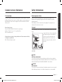
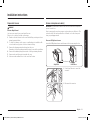
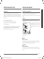
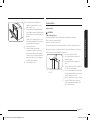
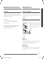
Transport
To avoid damage to the oven vent, use the transport method shown in the picture
below.
A
B
A. Front
B. Pallet
Support the bottom of the oven from either
side when moving it into the installation
location. Leave the unit attached to the
shipping pallet until it is in front of the
cabinet opening and is ready to be lifted
into place.
DANGER
ELECTRICAL SHOCK HAZARD
To avoid risk of electrical shock, personal injury or death; verify your appliance
has been properly grounded in accordance with local codes or in absence of codes,
with the National Electrical Code (NEC). ANSI/NFPA 70-latest edition.
WARNING
MOVING HAZARD
To avoid risk of severe personal injury; this appliance requires two or more people
while handling and moving. Use of appliance moving devices is recommended.
Install_DOB30P977_DG68-01308A-00_EN+MES+CFR.indb 3 2020-06-24 �� 10:12:35

4 English
Safety informations
Safety informations
WARNING
• The information in this manual should be followed exactly.
• A re or electrical shock may result causing property damage, personal
injury or death.
• Important - Save this installation manual for local electrical inspector's use.
• Proper Installation - Be sure your appliance is properly installed and grounded
by a qualied technician.
• New branch-circuit installations (1996 NEC), mobile homes, recreational
vehicles, or installations where local codes prohibit grounding through the
neutral conductor require 4-wire branch-circuit connection.
• Improper connection of aluminum house wiring to copper leads can result in
an electrical hazard or re. Use only connectors designed for joining copper to
aluminum and follow the manufacturer’s recommended procedure closely.
• Mounting screws must be used.
• Failure to do so can result in the oven falling out of the cabinet causing
serious injury.
CAUTION
• Make sure the cabinets and wall coverings around the oven can withstand the
temperature (up to 194 °F [90 °C]) generated by the oven.
• Discoloration, delamination or melting may occur.
• DO NOT remove spacers on the side walls of the built-in oven.
• These spacers center the oven in the space provided. The oven must be
centered to prevent excess heat buildup that may result in heat damage
or re.
WARNING
• The information in this manual should be followed exactly.
• A re or electrical shock may result causing property damage, personal
injury or death.
IMPORTANT NOTE
Proper installation is the responsibility of the installer and product failure due to
improper installation is NOT covered under warranty.
WARNING
• DO NOT put any weight on the oven door. Never allow anyone to climb, sit,
stand or hang on the oven door.
• The oven could tip and injury might result from food or the oven itself.
WARNING
• The electrical power must be shut off while the electrical connections are
being made.
• Failure to do so can result in severe personal injury, death or electrical
shock.
IMPORTANT NOTE
• Observe all governing codes and ordinances. This appliance must be properly
grounded.
• Keep oven vent ducts unobstructed. The oven vent is located bottom of the
oven. This area could become hot during oven use. Never block this vent or
place plastic or heat-sensitive items in front of it.
Install_DOB30P977_DG68-01308A-00_EN+MES+CFR.indb 4 2020-06-24 �� 10:12:35

English 5
Preparation
Preparation
Checklist
Use this checklist to verify that you have completed each step of the installation
process. This can help you avoid mistakes.
1. Before installing the oven, be sure to verify the cabinet dimensions are correct
for your unit and the required electrical connections are present.
2. Refer to the installation manual for content regarding Safety, Cabinet
Dimensions, Removing Packaging, Electrical Installation, Testing the
Installation and Customer Service.
3. To lift up the oven, hang the install handle onto the side hook of the unit.
4. Move the oven unit into place in front of the cabinet opening, leaving the
bottom packaging on the unit to avoid damaging ooring.
5. Team lift the unit directly into the cabinet cutout taking care not to pinch
ngers or scratch hands or arms. Make sure the electrical conduit reaches to
the connection point properly.
6. Slide the unit all the way into place, making sure to route the electrical conduit
correctly.
7. Fasten the oven unit to the cabinetry opening with screws supplied (using
Phillips screwdriver).
8. Consult the complete installation instructions and follow the remainder of the
procedures listed, including performing an operation test.
9. All product literature and accessories are supplied (may be wrapped or boxed)
with the oven.
10. INSTALLER - Leave the literature pack and the accessories with the customer.
11. Hang the install handle onto the side hook of the oven.
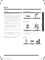
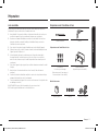
Prepare to install the oven
Phillips Screwdriver Drill
Prepare to install the oven
6 screws (M4 L16)
6 Wood Screw For Mounting
(4 needed for Single ovens and 6 needed
for double ovens)
Install Handle
(only for double oven)
Materials needed
Junction Box Wire Nuts 3/4” Conduit Connector
Install_DOB30P977_DG68-01308A-00_EN+MES+CFR.indb 5 2020-06-24 �� 10:12:35

6 English
Preparation
Preparation
Location requirements
IMPORTANT: Observe all governing codes and ordinances.
• Cabinet opening dimensions that are shown must be used.
Given dimensions provide minimum clearance with oven.
• Recessed installation area must provide complete enclosure around the
recessed portion of the oven.
• Grounded electrical supply is required. See “Electrical Requirements”
section.
• Electrical supply junction box should be located 3” (76 mm) maximum below
the support surface when the oven is installed in a wall cabinet. A 1” (26 mm)
minimum diameter hole should have been drilled in the right rear or left
rear corner of the support surface to pass the appliance cable through to the
junction box.
NOTE
For under counter installation, it is recommended that the junction box be located
in the adjacent right or left cabinet. If you are installing the junction box on rear
wall behind oven, it is recommended that the junction box be recessed and located
in the upper Right of the cabinet.
• Oven support surface must be solid, level and ush with bottom of cabinet
cutout.
• Floor must be able to support a single oven weight of 199 lb (90 Kg).
• Floor must be able to support a double oven weight of 331 lb (150 Kg).
IMPORTANT: To avoid damage to your cabinets, check with your builder or
cabinet supplier to make sure that the materials used will not discolor, delaminate
or sustain other damage. This oven has been designed in accordance with the
requirements of UL and CSA International and complies with the maximum
allowable wood cabinet temperatures of 194 °F (90 °C).
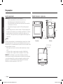
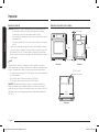
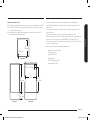
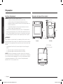
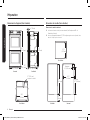
Product dimensions - single ovens
287/8”
(731 mm)
271/4”
(691 mm)
31/2”
(89 mm)
293/4” (756 mm)
Front view
231/8” (587 mm)
Side view
13/8” (33 mm)
28/”
(724 mm)
47/” (1200 mm)
Conduit length
Top view
Install_DOB30P977_DG68-01308A-00_EN+MES+CFR.indb 6 2020-06-24 �� 10:12:35

English 7
Preparation
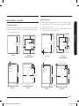
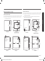
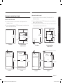
Cabinet dimensions - single ovens
Standard cabinet dimensions
01 Dimensions provide minimum reveals. (except electrical supply location ‘E’)
02 Allow a minimum of 22”
(559 mm)
for clearance to adjacent corners, drawers,
walls, etc. when door is open.
231/2”
(597 mm)
281/2”
(724 mm)
1” (26 mm)
195/8”
(498 mm)
1” (26 mm)
11/8” (28 mm)
11/2” (38 mm)
Top view Top view
(Cooktop installation)
Side view Front view
271/4”
(692 mm) 281/2”
(724 mm)
Min. 22”
(559 mm)
Max. 91/2” (241 mm)
5” (127 mm)
4” (101 mm)
For cooktop
installation
Flush cabinet dimensions
01 Dimensions provide minimum reveals. (except electrical supply location ‘E’)
02 Allow a minimum of 22”
(559 mm)
for clearance to adjacent corners, drawers,
walls, etc. when door is open.
03 Flush installation requires recessed strips (not included) attached to the side of
the cabinet opening for mounting the oven.
247/8”
(630 mm)
281/2”
(724 mm)
1” (26 mm)
195/8”
(498 mm)
1” (26 mm)
1/” (33 mm)
11/8” (28 mm)
11/2” (38 mm)
Top view Top view
(Cooktop installation)
Side view Front view
29” (737 mm)
7/8” (20 mm) Cleat width
301/4”
(767 mm)
Min. 22”
(559 mm)
Max. 91/2” (241 mm)
5” (127 mm)
21/4” (57 mm)
For cooktop
installation
Install_DOB30P977_DG68-01308A-00_EN+MES+CFR.indb 7 2020-06-24 �� 10:12:36

8 English
Preparation
Preparation
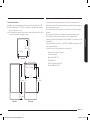
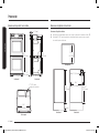
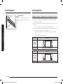
Cabinet dimensions - double ovens
Standard cabinet dimensions
01 Dimensions provide minimum reveals. (except electrical supply location ‘E’)
02 Allow a minimum of 22”
(559 mm)
for clearance to adjacent corners, drawers,
walls, etc. when door is open.
281/2”
(724 mm)
231/2”
(597 mm)
501/4”
(1276 mm)
12”
(305 mm)
Min. 47”
(1194 mm)
Top view
Side view Front view
Max. 91/2” (241 mm)
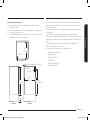
Product dimensions - double ovens
511/2”
(1307 mm)
497/8”
(1267 mm)
31/2”
(89 mm)
293/4” (756 mm)
Front view
231/8” (587 mm)
Side view
13/8” (33 mm)
28/”
(724 mm)
67” (1700 mm)
Conduit length
Top view
Install_DOB30P977_DG68-01308A-00_EN+MES+CFR.indb 8 2020-06-24 �� 10:12:36

English 9
Preparation
If codes permit and a separate ground wire is used, it is recommended that a
qualied electrical installer determine that the ground path and the wire gauge are
in accordance with local codes.
Check with a qualied electrical installer if you are not sure the oven is properly
grounded.
This oven must be connected to a grounded-metal permanent wiring system.
Be sure that the electrical connection and wire size are adequate and in
conformance with the National Electrical Code, ANSI/NFPA 70-latest edition or CSA
Standards C22.
1-94, Canadian Electrical Code, Part 1 and C22.2 No. O-M91-latest edition, and all
local codes and ordinances.
A copy of the above code standards can be obtained from:
National Fire Protection Association
1 Batterymarch Park
Quincy, MA 02169-7471
CSA International
8501 East Pleasant Valley Road
Cleveland, OH 44131-5575
Flush cabinet dimensions
01 Dimensions provide minimum reveals. (except electrical supply location ‘E’)
02 Allow a minimum of 22”
(559 mm)
for clearance to adjacent corners, drawers,
walls, etc. when door is open.
03 Flush installation requires recessed strips (not included) attached to the side of
the cabinet opening for mounting the oven.
301/4”
(767 mm)
247/8”
(630 mm)
517/8”
(1316 mm)
12”
(305 mm)
Min. 47”
(1194 mm)
Top view
Side view Front view
Max. 91/2” (241 mm)
13/8” (33 mm)
7/8” (20 mm) Cleat width
Install_DOB30P977_DG68-01308A-00_EN+MES+CFR.indb 9 2020-06-24 �� 10:12:36

10 English
Preparation
Preparation
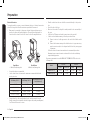
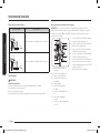
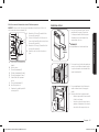
Electrical Connection
To properly install your oven, you must determine the type of electrical connection
you will be using and follow the instructions provided in this manual.
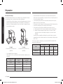
• Oven must be connected to the proper electrical voltage and frequency as
specied on the model/serial/rating plate. The model/serial/rating plate is
located on the bottom left side of the trim. See the following illustrations.
A
A
Single Oven
A. Model/serial/rating plate
Double Oven
A. Model/serial/rating plate
• A circuit breaker is recommended.
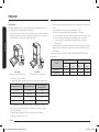
• Use the chart below to determine the minimum recommended dedicated
circuit protection.
KW Rating (240 V) KW Rating (208 V) Recommended Circuit
Size (Dedicated)
≤4.8 KW ≤4.1 KW 20 Amp
4.9 KW - 7.5 KW 4.3 KW - 6.2 KW 30 Amp
7.3 KW - 9.6 KW 6.3 KW - 8.3 KW 40 Amp
9.7 KW - 12.0 KW 8.4 KW - 10.4 KW 50 Amp
• Connect directly to the circuit breaker box (or fused disconnect) through
exible, armored or nonmetallic sheathed, copper cable (with grounding wire).
See “Electrical Connection” section.
• Flexible conduit from the oven should be connected directly to the junction
box.
• Fuse both sides of the line.
• Do not cut the conduit. The length of conduit provided is for serviceability of
the oven.
• A UL listed or CSA approved conduit connector must be provided.
• If the house has aluminum wiring, follow the procedure below:
1. Connect a section of solid copper wire to the ends of the exible conduit
leads.
2. Connect the aluminum wiring to the added section of copper wire using
special connectors and/or tools designed and UL listed for joining copper
to aluminum.
Follow the electrical connector manufacturer's recommended procedure.
Aluminum/copper connection must conform with local codes and industry
accepted wiring practices.
For power requirements for models DOB30P977SS,DOB30P977DS refer to the
following table.
Model 240 VAC 208 VAC
Power Circuit Size Power Circuit Size
DOB30P977SS 5.6 kW 30 Amp 4.2 kW 30 Amp
DOB30P977DS 11.2 kW 50 Amp 8.4 kW 50 Amp
Install_DOB30P977_DG68-01308A-00_EN+MES+CFR.indb 10 2020-06-24 �� 10:12:36

English 11
Installation instructions
Installation instructions
Prepare built-in oven
WARNING
Excessive Weight Hazard
Use two or more people to move and install an oven.
Failure to do so can result in back or other injury.
1. Decide on the nal location for the oven. Avoid drilling or cutting into house
wiring during installation.
2. To avoid oor damage, set the oven on a cardboard prior to installation. Do
not use handle or any portion of the front frame for lifting.
3. Remove the shipping materials and tape from the oven.
Remember to keep the packing materials that may be needed for installation.
4. Remove the hardware package from inside of the bag containing literature.
5. Remove racks and other parts from inside the oven.
6. Move oven and cardboard close to the oven’s nal location.
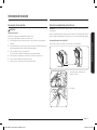
Remove and replace oven door(s)
IMPORTANT: Use two hands to remove oven door. For double ovens, repeat the
process for each door.
Prior to removing the oven door, prepare a surface where you will place it. This
surface should be at and covered with a soft blanket, or use the corner posts
from your packaging material.
Disconnect LED light wire harness
Locate the LED light wire harness and disconnect it before removing the door.
Wire Harness
Single Oven Double Oven
1. Carefully pull the wire to reveal the
connector.
2. Disconnect the connector.
Install_DOB30P977_DG68-01308A-00_EN+MES+CFR.indb 11 2020-06-24 �� 10:12:36

12 English
Installation instructions
Installation instructions
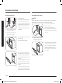
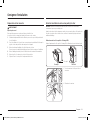
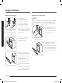
Remove oven door(s)
AB
A. Oven door hinge lock in
locked position
B. Oven door hinge lock in
unlocked position
1. Open the oven door.
2. Locate the oven door hinge locks in
both corners of the oven door, and
then rotate the hinge locks toward the
oven door to the unlocked position (see
illustration B). If the door hinge lock
is not rotated fully, the door will not
remove properly.
3. Partially close the door to engage the
door latch locks.
The door will stop at this point.
4. Using two hands, grasp the edges of
the oven door. Lift and pull the oven
door toward you and remove. You may
need to gently shift door from side to
side as you pull.
5. Set the oven door(s) aside on the
prepared covered work surface with the
oven door resting on its handle.
6. To continue with the oven installation,
go to the “Positioning Oven Feet
for Multiple Cabinet Cutout Heights”
section.
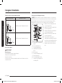
Replace oven door(s)
CAUTION
The door is very heavy. You may need help lifting the door high enough to slide it
into the hinge slots. Do not lift the door by the handle.
A
A. Slot in the oven cavity for
door hinge lock
1. Using two hands, grasp side edges of
door at the midpoint.
Face the oven cavity.
2. Locate the slots on each side of the
oven cavity for the door hinge locks.
3. At a 45° angle, align door hinges with
slots in the lower front of the oven
cavity. Slowly insert door, making sure
you maintain the 45° angle. You will
know the door is engaged in the slot
when you feel a slight drop.
Install_DOB30P977_DG68-01308A-00_EN+MES+CFR.indb 12 2020-06-24 �� 10:12:36

English 13
Installation instructions
4. Lower the oven door to the fully open
position. If the oven door does not open
to a full 90°, repeat steps 1 through 3.
5. Locate the oven door hinge locks in the
corners of the oven door, and rotate the
hinge locks toward the oven cavity to
the locked position.
See Step 1 (illustration A) in the
“Remove Oven Door(s)” section for
proper locked position.
6. Close the oven door.
7. When the hinges are properly installed
and the door closed, there should be
an even gap between the door and the
control panel. If one side of the oven
door is hanging lower than the other,
the hinge on that side is not properly
installed.
8. Connect Wire Harness.
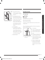
Electrical connection
For Double Ovens
WARNING
Electrical Shock Hazard
Disconnect power before servicing.
Use 8 gauge solid copper wire.
Make sure to ground the oven.
Failure to follow these instructions can result in death, re, or electrical shock.
This oven is manufactured with a neutral (white) power supply wire and a cabinet-
connected ground (green or bare) wire twisted together.
A
A. UL listed or CSA approved
conduit connector
1. Disconnect power.
2. Feed the exible conduit from the oven
through the opening in the cabinet.
3. Remove junction box cover if it is
present.
4. Install a UL listed or CSA approved
conduit connector to the junction box.
5. Route the exible conduit from the
oven to the junction box through a
UL listed or CSA approved conduit
connector.
6. Tighten screws on conduit connector.
7. See “Electrical Connection Options
Chart” to complete installation for your
type of electrical connection.
Install_DOB30P977_DG68-01308A-00_EN+MES+CFR.indb 13 2020-06-24 �� 10:12:37

14 English
Installation instructions
Installation instructions
Electrical Connection Options Chart
If your home has: Go to section:
4-wire
(1.3 cm)
½”
4-Wire Cable from Home Power Supply
3-wire
(1.3 cm)
½”
3-Wire Cable from Home Power Supply
For Single Ovens
WARNING
Electrical Shock Hazard
Disconnect power before servicing.
Use 8 gauge solid copper wire.
Electrically ground oven.
Failure to follow these instructions can result in death, re, or electrical shock.
4-Wire Cable from Home Power Supply
IMPORTANT: Use the 4-wire cable from home power supply in the U.S. where local
codes do not allow grounding through neutral, New Branch circuit installations
(1996 NEC), mobile homes and recreational vehicles, new construction and in
Canada.
A
E
B
G
H
I
C
D
F
A. Cable from home power
supply
B. Black wires (normally L1)
C. Red wires (normally L2)
D. 4-wire exible conduit from
oven
E. Junction box
F. White wires (normally
N-neutral)
G. UL listed wire connectors
H. green wires (normally
G-ground)
I. UL listed or CSA approved
conduit connector
1. Connect the 2 black wires (B) together
using a UL listed wire connector.
2. Connect the 2 red wires (C) together
using a UL listed wire connector.
3. Untwist white wire from green (or bare)
ground wire coming from the oven.
4. Connect the 2 white wires (F) together
using a UL listed wire connector.
5. Connect the green (or bare) ground
wire (H) from the oven cable to the
green (or bare) ground wire (in the
junction box) using a UL listed wire
connector.
6. Install junction box cover.
Install_DOB30P977_DG68-01308A-00_EN+MES+CFR.indb 14 2020-06-24 �� 10:12:37

English 15
Installation instructions
3-Wire Cable from Home Power Supply - U.S. Only
IMPORTANT: Use the 3-wire cable from home power supply where local codes
permit a 3-wire connection.
A
E
B
G
H
I
C
D
F
A. Cable from home power
supply
B. Junction box
C. Black wires (normally L1)
D. White wires (normally
N-neutral)
E. green wires (normally
G-ground)
F. 4-wire exible conduit from
oven
G. Red wires (normally L2)
H. UL listed wire connectors
I. UL listed or CSA approved
conduit connector
1. Connect the 2 black wires (C) together
using a UL listed wire connector.
2. Connect the 2 white wires (D) and
the green (or bare) ground wire (of
the oven cable) using a UL listed wire
connector.
3. Connect the 2 red wires (G) together
using a UL listed wire connector.
4. Install junction box cover.
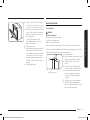
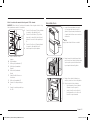
Install oven
Install
Handle
1. Using 2 or more people, lift the oven
partially into the cabinet cutout. Hang
the install handle onto the side hook of
the oven as shown below.
NOTE
Carefully push against front oven frame.
2. Push against the seal area of the front
frame to push the oven into the cabinet
until the back surface of the front frame
touches the front wall of the cabinet.
3. Push oven completely into the cabinet
and center the oven into the cabinet
cutout.
4. Remove the tape from front trims.
• Securely fasten the oven to the
cabinet using the screws provided.
• Insert the screws through hole in
trim aligning with hole in oven
frame. Do not overtighten screws.
Install_DOB30P977_DG68-01308A-00_EN+MES+CFR.indb 15 2020-06-24 �� 10:12:37

16 English
Self-diagnosis
Self-diagnosis
Barrier
WARNING
When inserting the oven, use caution not to
deform or damage the barrier underneath.
Self-diagnosis
Temp sensor & Heater check
1. After connecting the power, check if the display works properly.
2. Remove all accessories (Gliding Rack, Flat-Rack, Smart Divider...etc.) from
inside of the oven cavity.
3. You cannot proceed with self-diagnosis if the oven cavity is hot or the door is
open.
• In this case, “Hot or door” message appears on the display.
4. To start self-diagnosis, press both Hidden Keys simultaneously for 5 seconds
and select install test button.
• Refer to the table below for the hidden keys for each model.
• Self-diagnosis takes approximately 6-7 minutes.
Model DOB30P977DS
Control panel
Hidden Key UPPER + LOWER
Model DOB30P977SS
Control panel
Hidden Key SETTING + RESERVOIR
Install_DOB30P977_DG68-01308A-00_EN+MES+CFR.indb 16 2020-06-24 �� 10:12:37

English 17
Self-diagnosis
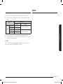
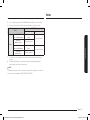
5. If there is no error, 'PASS' appears on the display with an alert sound.
6. If there is an error, following message appears on the display with an alert
sound.
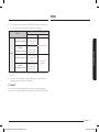
Model DOB30P977**
Error code Remark
Feature
Upper Broil Upper Broil Fail Double/Single Oven
Upper Bake Upper Bake Fail
Lower Broil Lower Broil Fail Double Oven Only
Lower Bake Lower Bake Fail
7. If an error occurs, contact a Dacor service center for further service.
8. If nish self-diagnosis, press both Hidden Keys simultaneously for 5 seconds
to return to normal standby mode.
NOTE
If you see any other error messages that are not listed above, please contact a
Dacor service center at 833-35-ELITE (833-353-5483).
Memo
Install_DOB30P977_DG68-01308A-00_EN+MES+CFR.indb 17 2020-06-24 �� 10:12:37

18 English
Memo
Install_DOB30P977_DG68-01308A-00_EN+MES+CFR.indb 18 2020-06-24 �� 10:12:37

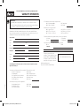
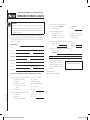
IMPORTANT:
Your warranty will not begin until you activate it online or return this form to
Dacor. If you have purchased more than one Dacor product, please return all forms
in one envelope, or activate the warranty for each product online.
Please rest assured that under no conditions will Dacor sell your name or any of the
information on this form for mailing list purposes. We are very grateful that you
have chosen Dacor products for your home and we do not consider the sale of such
information to be a proper way of expressing our gratitude!
Owner’s Name:
Street: Last (Please Print or Type) First Middle
City: State:
Zip:
Purchase Date: Email:
Telephone:
Dealer:
City: State:
Zip:
Your willingness to take a few seconds to ll in the section below will be sincerely
appreciated. Thank you.
1. How were you rst exposed to Dacor products? (Please check one only.)
A. T.V. Cooking Show F. Builder
B. Magazine G. Architect/Designer
C. Appliance Dealer Showroom H. Another Dacor Owner
D. Kitchen Dealer Showroom I. Model Home
E. Home Show J. Other
2. Where did you buy your Dacor appliances?
A. Appliance Dealer D. Builder
B. Kitchen Dealer E. Other
C. Builder Supplier
Please visit www.Dacor.com to activate your warranty online.
WARRANTY INFORMATION
cut herecut here
3. For what purpose was the product purchased?
A. Replacement
only
C. New Home
B. Part of a Remodel D. Other
4. What is your household income?
A. Under $75,000 D. $150,000 – $200,000
B. $75,000 – $100,000 E. $200,000 – $250,000
C. $100,000 – $150,000 F. Over $250,000
5. What are the brands of appliances that you have in your kitchen?
A. Cooktop C. Dishwasher
B. Oven D. Refrigerator
6. Would you buy or recommend another Dacor product?
Yes No
Comments:
Thank you very much for your
assistance. The information you have
provided will be extremely valuable
in helping us plan for the future and
giving you the support you deserve.
Place Serial Number Label Here
Website: www.Dacor.com
Phone: 833-35-ELITE (833-353-5483)
Install_DOB30P977_DG68-01308A-00_EN+MES+CFR.indb 19 2020-06-24 �� 10:12:37

Dacor ∙ 14425 Clark Avenue, City of Industry, CA 91745
∙ Phone: 833-35-ELITE (833-353-5483) ∙ Fax: (626) 403-3130 ∙ www.dacor.com
DG68-01308A-00
Install_DOB30P977_DG68-01308A-00_EN+MES+CFR.indb 20 2020-06-24 �� 10:12:38
La page charge ...
La page charge ...
La page charge ...
La page charge ...
La page charge ...
La page charge ...
La page charge ...
La page charge ...
La page charge ...
La page charge ...
La page charge ...
La page charge ...
La page charge ...
La page charge ...
La page charge ...
La page charge ...
La page charge ...
La page charge ...
La page charge ...
La page charge ...
La page charge ...
La page charge ...
La page charge ...
La page charge ...
La page charge ...
La page charge ...
La page charge ...
La page charge ...
La page charge ...
La page charge ...
La page charge ...
La page charge ...
La page charge ...
La page charge ...
La page charge ...
La page charge ...
La page charge ...
La page charge ...
La page charge ...
La page charge ...
-
 1
1
-
 2
2
-
 3
3
-
 4
4
-
 5
5
-
 6
6
-
 7
7
-
 8
8
-
 9
9
-
 10
10
-
 11
11
-
 12
12
-
 13
13
-
 14
14
-
 15
15
-
 16
16
-
 17
17
-
 18
18
-
 19
19
-
 20
20
-
 21
21
-
 22
22
-
 23
23
-
 24
24
-
 25
25
-
 26
26
-
 27
27
-
 28
28
-
 29
29
-
 30
30
-
 31
31
-
 32
32
-
 33
33
-
 34
34
-
 35
35
-
 36
36
-
 37
37
-
 38
38
-
 39
39
-
 40
40
-
 41
41
-
 42
42
-
 43
43
-
 44
44
-
 45
45
-
 46
46
-
 47
47
-
 48
48
-
 49
49
-
 50
50
-
 51
51
-
 52
52
-
 53
53
-
 54
54
-
 55
55
-
 56
56
-
 57
57
-
 58
58
-
 59
59
-
 60
60


Yes DOB30P977SS Guide d'installation
- Taper
- Guide d'installation
- Ce manuel convient également à
dans d''autres langues
- español: Yes DOB30P977SS Guía de instalación
Documents connexes
Autres documents
-
Samsung NV51M9770DS Guide d'installation
-
Samsung NQ70M9770DS Guide d'installation
-
Samsung DTI30P876BB Guide d'installation
-
-
-
-
-
-