Fortin 109621 Manuel utilisateur
- Catégorie
- Alarme de voiture
- Taper
- Manuel utilisateur

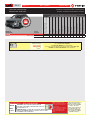
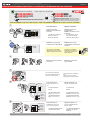
* HOOD PIN HOOD STATUS : THE HOOD PIN SWITCH MUST BE INSTALLED
IF THE VEHICLE CAN BE REMOTE STARTED WITH THE HOOD OPEN,
SET FUNCTION A11 TO OFF.
CONTACT
DE CAPOT
MANDATORY INSTALL | INSTALLATION OBLIGATOIRE Notice: the installation of safety
elements are mandatory. The hood pin
is an essential security element and
must be installed.
Notice: l'installation des éléments de
sécurité est obligatoire. Le contact de
capot est un élément de sécurité
essentiel et doit absolument être
installé.
THIS MODULE MUST BE INSTALLED BY A
QUALIFIED TECHNICIAN. A WRONG
CONNECTION CAN CAUSE PERMANENT
DAMAGE TO THE VEHICLE.
CE MODULE DOIT ÊTRE INSTALLÉ PAR
UN TECHNICIEN QUALIFIÉ, TOUTE
ERREUR DANS LES BRANCHEMENTS
PEUT OCCASIONNER DES DOMMAGES
PERMANENTS AU VÉHICULE.
STATUT DE CAPOT : LE CONTACT DE CAPOT, DOIT ÊTRE INSTALLÉ SI LE
VÉHICULE PEUT DÉMARRER À DISTANCE, LORSQUE LE CAPOT EST OUVERT,
PROGRAMMEZ LA FONCTION A11 À NON.
A11 OFF
NON
ADDENDUM - SUGGESTED WIRING CONFIGURATION
ADDENDA - SCHÉMA DE BRANCHEMENT SUGGÉRÉ
ALL REV.: 20230531
1-Page_entete
Guide # 109621
Vehicle functions supported in this diagram (functional if equipped) | Fonctions du véhicule
supportées dans ce diagramme (fonctionnelles si équipé)
Immobilizer bypass
Contournement d’immobilisateur
Lock
Unlock
Arm
Disarm
Parking Lights
Hatch (Open)
Tachometer
Door Status
Hood Status
Hand-Brake Status
Foot-Brake Status
OEM Remote monitoring
VEHICLE
VEHICULES
YEARS
ANNÉES
DODGE
Journey
Push-to-start
2011-2017
•
•
•
•
•
•
•
•
•
•
•
•
•
Guide # 94671
FIRMWARE VERSION
VERSION LOGICIELLE To add the rmware version and the options,
use the FLASH LINK UPDATER
or FLASH LINK MOBILE tool, sold separately.
Pour ajouter la version logicielle et les options, utilisez l’outil FLASH LINK
UPDATER ou FLASH LINK MOBILE, vendu séparément.
69.[04]
MINIMUM
THAR-CHR7 INSTALLATION
INSTALLATION THAR-CHR7
Con-
Page 1 / 9

This guide may change without notice. See www.fortin.ca for latest version.
Ce guide peut faire l’objet de changement sans préavis. Voir www.fortin.ca pour la récente version.
2-PagesSuivantes
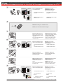
NOTES
Program bypass option
(If equiped with OEM alarm):
Programmez l’option du contournement
(Si équipé d’une alarme d’origine):
D2
Unlock before / Lock after (Disarm OEM
alarm)
Déverrouille avant / Verrouille après
(Désarme l’alarme d’origine)
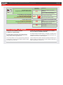
NOTES 12V BATTERY | 12V BATTERIE
ATTENTION THE T-HARNESS CURRENT
IS LIMITED AT 5 AMP MAXIMUM.
If a parking lights (+) wire is use : that require more than
5Amp. Connect the remote-starter’s power directly to the
vehicles battery with the appropriate fuse.
Some remote starters can not be powered through Data-Link.
In these cases connect the remote starter’s fused 12V power
wire directly to the T-Harness.
ATTENTION LE COURANT DU 12V PROVENANT DU HARNAIS-
EN-T EST LIMITÉ À 5 AMPÈRES MAXIMUM.
Si le l des lumières de stationnement (+) est utilisé: il requière plus de
5 Ampères, branchez le 12V du démarreur à distance directement à la
batterie du véhicule avec le fusible approprié.
Certains démarreurs à distance NE peuvent PAS être allimentés par le
Data-Link. Dans ce cas, branchez le 12V (avec fusible) du démarreur à
distance directement au harnais-en-T.
D6 Push-to-Start
Push-to-Start
Program bypass option:
Programmez l’option du contournement:
UNIT OPTION
OPTION UNITE DESCRIPTION
C1
OEM Remote status (Lock/Unlock)
monitoring
Suivi des status (Verrouillage/Déverrouil-
lage) de la télécommande d’origine
IF THE VEHICLE IS NOT EQUIPPED
WITH FUNCTIONAL HOOD PIN:
SI LE VÉHICULE N’EST PAS ÉQUIPÉ
D’UN CONTACT DE CAPOT FONCTIONNEL:A11 OFF
NON
Hood trigger (Output Status).
Contact de capot (état de sortie).
Page 2 / 9

This guide may change without notice. See www.fortin.ca for latest version.
Ce guide peut faire l’objet de changement sans préavis. Voir www.fortin.ca pour la récente version.
2-PagesSuivantes
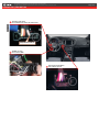
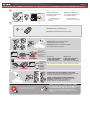
DESCRIPTION | DESCRIPTION
Back of Push-to-Start Button
Dos du Bouton poussoir
At Parking Lights switch
Au commutateur des lumières de stationnement
(MUX)PARKING LIGHTS
JOURNEY
At OBDII connector
Au connecteur OBDII
Page 3 / 9

This guide may change without notice. See www.fortin.ca for latest version.
Ce guide peut faire l’objet de changement sans préavis. Voir www.fortin.ca pour la récente version.
2-PagesSuivantes
Yellow In A1
Purple In A2
Purple/White In A3
Green Out A4
White Out A5
Orange In A6
Orange/Black In A7
Dk.Blue In A8
Red/Blue In A9
Lt.Blue/Black A10
Black Out A11
Pink Out A12
Yellow/Black In A13
Brown/White Out A14
Pink/Black Out A15
Purple/Yellow A16
Green/White A17
Green/Red A18
White/Black A19
Lt.Blue A20
C5 Brown
C4 Gray/Black
C3 Gray
C2 Orange/Brown
C1 Orange/Green
D6 White/Red
D5 White/Blue
D4 White/Green
D3 Yellow/Red
D2 Yellow/Blue
D1 Yellow/Green
AC
D
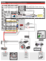
THAR-CHR7 | WIRING CONNECTION | GUIDE DE BRANCHEMENTS
B
HOOD IN RS8
(-)
HAND BRAKE IN RS9
(-)
TRUNK RELEASE
(-) OUT RS11
(+/-) IN RS12
TACHOMETER
F
OOT
B
RAKE
(+)
IN RS13
GROUND OUT WHILE RUNNING
(-) OUT RS14
TRUNK
(-)
IN RS17
DOOR
(-) IN RS18
UNLOCK
(-) OUT RS19
LOCK
(-) OUT RS20
A15
A14
A13
A12
A11
A8
A5
A4
A3
A2
Ground | Masse
(-)
RS1
12V BATTERY
RS2 IN
(+)
IGNITION
RS6 IN/OUT (+)
STARTER
RS7 OUT (+)
(-) Hood Status
(-) Hand Brake
(-) Trunk Release
(-/+) Tachometer
(+) Foot Brake
(+)Start
(-) Ground While Running
(-) Trunk Status
(-) Door Status
(-) Unlock
(-) Lock
(+) Ignion
A2
A3
A4
A5
A6
A7
A8
A9
A10
A11
A12
A13
A14
A15
A16
A17
A18
A19
A20
C5
C4
C3
C2
C1
D6
D5
D4
D3
D2
D1
A1
C1
C2
C5
A19
A17
A7
A6
(MUX)PARKING
LIGHTS
654321
White/Brown
Blanc/Brun
2
1
3
Back View - Black 6-pin
Connector -At Parking
Lights switch.
Vue de dos - Connecteur
Noir de 6 pins - Au
commutateur
des lumières de
stationnement.
JOURNEY
PUSH
START
T-HARNESS - HARNAIS EN T
THAR-CHR7-B
T-HARNESS - HARNAIS EN T
THAR-CHR7-A
MALE T-HARNESS
IGNITION PLUG
CONNECTEUR D’IGNITION
DU T-HARNAISMÂLE
FEMALE T-HARNESS
IGNITION PLUG
CONNECTEUR D’IGNITION
DU T-HARNAISFEMELLE
MALE VEHICLE
IGNITION PLUG
CONNECTEUR MÂLE
D’IGNITION
DU VÉHICULE
Back View
6-pin Black
Connector
At Push-to-Start
button.
Vue de dos
Connecteur Noir
de 6-pins
Au boutton de
démarrage.
Front View - 16-pin
OBDII Connector.
Vue de face -
Connecteur Blanc de
2-pins - OBDII.
16 PIN
MALE T-HARNESS PLUG
CONNECTEUR MÂLE
DU T-HARNAIS
FEMALE T-HARNESS PLUG
CONNECTEUR FEMELLE
DU T-HARNAIS
Replace factory
OBDII connector
Remplace le connecteur
OBDII d’origine
T-HARNESS - HARNAIS EN T
THAR-CHR7-B
5 PIN CONN.
NOT USED
NE PAS UTILISER
T-HARNESS - HARNAIS EN T
OBD2-GENERIC
2
RS6
A1
(+) IGNITION OUT OUT
A9
B
Black
Red 12V BATTERY
GROUND
Cut | Coupez
Cut | Coupez
ALWAYS REQUIRED
TOUJOURS REQUIS
NOT REQUIRED WITH
DATALINK
NON REQUIS EN
DATA-LINK
REMOTE
STARTER
DÉMARREUR
À DISTANCE
WITH | AVEC DATA-LINK:
Direct connection
Branchement directe
OR
OU
WITH D2D:
AVEC D2D: WITHOUT
SANS
DATA-LINK:
WITH DATA-LINK:
AVEC DATA-LINK:
Use the DATA-LINK cable
supplied wih the module.
U�lisez le câble
DATA-LINK inclus avec le
module.
5 PIN CONN.5 PIN CONN.
A18
(MUX)Parking Lights
Black
RedB4
B3
12V Battery
Ground
6 PIN CONN.
Page 4 / 9

Release the programming
button when the LED is BLUE.
2
1
3
Relâchez le bouton de
programmation quand la DEL
est BLEU.
Insert the required remaining
connectors. Insérez les connecteurs
requis restants.
x1
HOLD
Press and hold
Insert
the
programming button:
the 4-Pin (Data-Link)
connector.
Appuyez maintenir
enfoncé
Insérez
et
le bouton de
programmation:
le connecteur 4 pins
(Data-Link)
The Blue, Red, Yellow and
Blue & Red LEDs will
alternatively illuminate.
Les DELs Bleue, Rouge,
Jaune et Bleue & Rouge
s'allumeront alternativement.
LED may differ depending on the module casing.
L’apparence des DELS peut différer selon le boîtier du module.
RELEASE
If the LED is not solid BLUE
disconnect the 4-Pin connector
(Data-Link) and go back to step 1.
ON BLUE
BLEU
Si le DEL n'est pas BLEU
débranchez le connecteur 4
pins (Data-Link) et allez au
début de l'étape 1.
x1
PRESS
FLASH
RAPIDLY
FLASH
RAPIDLY
OFF
IGNITION ON PRESS X1
ON
FLASH
RAPIDLY
FLASH
RAPIDLY
IGNITION OFF
4
IGN ON
x2
PRESS
Ne pas appuyer sur la pédale de
frein.
Appuyez 2 fois sur le bouton
démarrage pour allumer l'ignition.
Do not press the brake pedal.
Press the START/STOP button
twice to turn ON the ignition.
5
The BLUE LED will flash
rapidly (CAN1 detection).
The RED LED will flash
rapidly (CAN2 detection).
La DEL BLEUE clignotera
rapidement (détection CAN1).
La DEL ROUGE clignotera
rapidement (détection CAN2).
The RED and BLUE LED will
continued to flash rapidly.
Les DELs ROUGE et BLEU
continueront de clignoter
rapidement.
Press and release the
programming button once
(1x).
Appuyez et relâchez 1 fois
le bouton de programmation.
will
turn off.
The BLUE LED
s'éteint.
La DEL BLEUE
Press and release the
START/STOP button once
(1x) to shut off the ignition.
Appuyez et relâchez 1 fois
le bouton START/STOP pour
éteindre l‘ignition.
OFF
x1
6
CONTINUED NEXT PAGE | CONTINUEZ À LA PAGE SUIVANTE
This guide may change without notice. See www.fortin.ca for latest version.
Ce guide peut faire l’objet de changement sans préavis. Voir www.fortin.ca pour la récente version.
2-PagesSuivantes
DCRYPTOR PROGRAMMING PROCEDURE | PROCÉDURE DE PROGRAMMATION AVEC DCRYPTOR
Parts required (not included) Pièces requises (non incluses)
1x FLASH LINK UPDATER,
1x FLASH LINK MANAGER
1x FLASH LINK MOBILE
1x FLASH LINK MOBILE APP
SOFTWARE | PROGRAMME
Smartphone Android or iOS with Internet connection
(Internet provider charges may apply)
Téléphone Intelligent Android ou iOS avec connection
Internet (des frais du fournisseur Internet peuvent s’appliquer)
OR
OU
Microsoft Windows Computer with Internet connection
Ordinateur Microsoft Windows avec connection Internet
1x1x
BEFORE PROGRAMMING SET THE UNIT OPTIONS AND SAVE. | AVANT LA PROGRAMMATION CONFIGURER LES OPTIONS DE L'UNITÉ ET SAUVEGARDER.
5.1-Prog.1-17-1-CHRY-PTS-DCRYPTOR_PRESS
Page 5 / 9

OFF
ON
ON
IGNITION OFF IGNITION ON
ON
ON
ON
IGNITION OFF ACCESORY
ON
OFF
OFF
ON
ALTERNATE
IGNITION OFF UNLOCK
OFF
will
turn off.
The BLUE LED
s'éteint.
La DEL BLEUE
8
9
10
11
12
+
PANIC
Remove the battery from the OEM remote
Retirer la pile de la télécommande d”origine
Place the OEM remote (no
battery) close to the front of
START/STOP button exactly
as shown.
Do not move the OEM remote for
the following step.
PANIC
Approchez la télécommande
d'origine (sans batterie) devant
le bouton START/STOP
exactement comme illustrée.
Ne pas bouger la télécommande
d'origine pour l'étape suivante.
Press the Start/Stop button
twice to turn ON the ignition.
PANIC
x2
ON
Appuyez sur le bouton
START/STOP X2 fois pour
allumer l'ignition.
The RED LED will turns ON. La DEL ROUGE s’allume.
The YELLOW LED will turns
OFF.
La DEL JAUNE s’éteind.
Press the Start/Stop button
twice to turn ON the ignition.
PANIC
x2
ON
Appuyez sur le bouton
START/STOP X2 fois pour
allumer l'ignition.
Press and release the
START/STOP button once to
shut off the ignition.
OFF
x1
Appuyez et relâchez le
bouton START/STOP pour
éteindre l'ignition.
Place the OEM remote (no
battery) close to the front of
START/STOP button as
shown.
Do not move the OEM remote for
the following step.
PANIC
Approchez la télécommande
d'origine (sans batterie)
devant le bouton
START/STOP comme
illustrée.
Ne pas bouger la télécommande
d'origine pour l'étape suivante.
13
The RED and YELLOW
LEDs will alternated.
La DEL ROUGE et JAUNE
alternent.
Press the UNLOCK button
on the OEM remote.
Appuyez sur le bouton
DÉVERROUILLAGE de la
télécommande d’origine
The RED and BLUE LED will
turns OFF.
Wait, the YELLOW LED will
turns ON solide.
Les DELs ROUGE et BLEUE
s’éteingnent.
The BLUE LED will turns ON. La DEL BLEUE s’allume.
Attendre que la DEL JAUNE
s’allume solide.
UNLOCK
PANIC
7
CONTINUED NEXT PAGE | CONTINUEZ À LA PAGE SUIVANTE
This guide may change without notice. See www.fortin.ca for latest version.
Ce guide peut faire l’objet de changement sans préavis. Voir www.fortin.ca pour la récente version.
2-PagesSuivantes
KEY BYPASS PROGRAMMING PROCEDURE 2/3 | PROCÉDURE DE PROGRAMMATION CONTOURNEMENT DE CLÉ 2/3
5.1-Prog.1-17-2-CHRY-PTS-DCRYPTOR_PRESS
Page 6 / 9

ALTERNATE
15
The RED and YELLOW
LEDs will continued to
alternated.
Les DELs ROUGE et
JAUNE continueront d’alterner.
Press and release the
START/STOP button once to
shut off the ignition.
OFF
x1 Appuyez et relâchez 1 fois
sur le bouton START/STOP
pour éteindre l'ignition.
Reinsert the battery in the OEM remote.
Réinsérez la pile dans la télécommande d'origine.
+
PANIC
14
EVO-ALL
Disconnect all the connectors and after
the Data-Link (4-pins) connector.
Débranchez tous les connecteurs et ensuite
le connecteur Data-Link (4-pins).
*Pièces requises (non incluses)
Use the tool:
FLASH LINK UPDATER or
FLASH LINK MOBILE
to visit the DCryptor menu.
Utilisez l'outil:
FLASH LINK UPDATER ou
FLASH LINK MOBILE
pour visiter le menu DCryptor.
*Parts required (not included)
FLASH LINK UPDATER*
FLASH LINK MOBILE*
FLASH LINK MANAGER*
SOFTWARE | PROGRAMME
Microsoft Windows
Computer with
Internet connection*
Ordinateur Microsoft
Windows avec
connection Internet*
VEHICLE'S OBDII
CONNECTOR
CONNECTEUR OBDII
DU VÉHICULE
OR
OU
Smartphone*
(Internet provider
charges
may apply)
Téléphone
Intelligent*
(des frais du
fournisseur
Internet peuvent
s’appliquer)
AFTER DCRYPTOR PROGRAMMING COMPLETED
Go back to the vehicle and reconnect the 4-Pin (Data-Link)
connector and after, all the remaining connector.
APRÈS LA PROCÉDURE DE PROGRAMMATION
DCRYPTOR COMPLETÉE : retournez au véhicule et
rebranchez le connecteur 4-pins (Data-Link)
et après, tous les connecteurs du EVO-ALL.
EVO-ALL
REMOTE STARTER / ALARM VERIFICATION
PROCEDURE | PROCÉDURE DE VÉRIFICATION
DU DÉMARREUR À DISTANCE / ALARME
Test the remote starter. Remote start the vehicle.
Testez le démarreur à distance. Démarrez le véhicule
à distance.
The module is now programmed.
Le module est programmé.
16
17
18
This guide may change without notice. See www.fortin.ca for latest version.
Ce guide peut faire l’objet de changement sans préavis. Voir www.fortin.ca pour la récente version.
2-PagesSuivantes
KEY BYPASS PROGRAMMING PROCEDURE 3/3 | PROCÉDURE DE PROGRAMMATION CONTOURNEMENT DE CLÉ 3/3
5.1-Prog.1-17-3-CHRY-PTS-DCRYPTOR_PRESS
Page 7 / 9

This guide may change without notice. See www.fortin.ca for latest version.
Ce guide peut faire l’objet de changement sans préavis. Voir www.fortin.ca pour la récente version.
2-PagesSuivantes
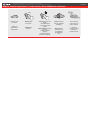
REMOTE STARTER FUNCTIONALITY | FONCTIONNALITÉS DU DÉMARREUR À DISTANCE
Remote start
Démarrez
the vehicle.
à
distance.
START
All doors must
be closed.
Toutes les
portes doivent
être fermées
UNLOCK
Enter
Entrez
the vehicle
with the Intelligent
SmartKey.
dans le
véhicule avec la
clé intelligente
(SmartKey) sur
vous
The vehicle can
now be put in to
gear and driven.
Vous êtes
maintenant prêt à
embrayer et
prendre la route.
Insert
Insérez
the key in
the Key port
la clé
dans le Key Port
Insert
START
All doors must
be closed.
Toutes les
portes doivent
être fermées
UNLOCK
Enter
Entrez
the vehicle
with the Intelligent
SmartKey.
dans le
véhicule avec la
clé intelligente
(SmartKey) sur
vous
The vehicle can
now be put in to
gear and driven.
Vous êtes
maintenant prêt à
embrayer et
prendre la route.
PUSH
START
Vehicles with key port.
Véhicules avec key port.
Vehicles with Push-to-Start.
Véhicules avec bouton Push-to-Start.
Unlock the doors with
either:
• The OEM remote
• The remote-starter
remote.
Déverrouillez les portes
avec soit:
• la télécommande
d'origine
• la télécomande du
démarreur à distance.
Unlock the doors with
either:
• The OEM remote
• The remote-starter
remote.
Déverrouillez les portes
avec soit:
• la télécommande
d'origine
• la télécomande du
démarreur à distance.
Remote start
Démarrez
the vehicle.
à
distance.
Page 8 / 9

ALL
Service No : 000 102 04 2536
Date: xx-xx
INTERFACE MODULE
Made in Canada
PATENTS PENDING US: 2007-228827-A1
www.fortinbypass.com
HARDWARE VERSION
FIRMWARE VERSION
Module label | Étiquette sur le module
Notice: Updated Firmware and Installation Guides
Updated fi rmware and installation guides are posted on our web site on a regular
basis. We recommend that you update this module to the latest fi rmware and
download the latest installation guide(s) prior to the installation of this product.
Notice: Mise à jour microprogramme et Guides d’installations
Des mises à jour du Firmware (microprogramme) et des guides d’installation
sont mis en ligne régulièrement. Vérifi ez que vous avez bien la dernière version
logiciel et le dernier guide d’installation avant l’installation de ce produit.
WARNING
The information on this sheet is provided on an (as is) basis with no representation or warranty of accuracy whatsoever.
It is the sole responsibility of the installer to check and verify any circuit before connecting to it. Only a computer safe
logic probe or digital multimeter should be used. FORTIN ELECTRONIC SYSTEMS assumes absolutely no liability or
responsibility whatsoever pertaining to the accuracy or currency of the information supplied. The installation in every case
is the sole responsibility of the installer performing the work and FORTIN ELECTRONIC SYSTEMS assumes no liability
or responsibility whatsoever resulting from any type of installation, whether performed properly, improperly or any other
way. Neither the manufacturer or distributor of this module is responsible of damages of any kind indirectly or directly
caused by this module, except for the replacement of this module in case of manufacturing defects. This module must be
installed by qualifi ed technician. The information supplied is a guide only. This instruction guide may change without
notice. Visit www.fortinbypass.com to get the latest version.
MISE EN GARDE
L’information de ce guide est fournie sur la base de représentation (telle quelle) sans aucune garantie de précision et
d’exactitude. Il est de la seule responsabilité de l’installateur de vérifi er tous les fi ls et circuits avant d’effectuer les connexions.
Seuls une sonde logique ou un multimètre digital doivent être utilisés. FORTIN SYSTÈMES ÉLECTRONIQUES n’assume
aucune responsabilité de l’exactitude de l’information fournie. L’installation (dans chaque cas) est la responsabilité de
l’installateur effectuant le travail. FORTIN SYSTÈMES ÉLECTRONIQUES n’assume aucune responsabilité suite à
l’installation, que celle-ci soit bonne, mauvaise ou de n’importe autre type. Ni le manufacturier, ni le distributeur ne se
considèrent responsables des dommages causés ou ayant pu être causés, indirectement ou directement, par ce module,
excepté le remplacement de ce module en cas de défectuosité de fabrication. Ce module doit être installé par un technicien
qualifi é. L’information fournie dans ce guide est une suggestion. Ce guide d’instruction peut faire l’objet de changement
sans préavis. Consultez le www.fortinbypass.com pour voir la plus récente version.
Copyright © 2006-2018, FORTIN AUTO RADIO INC ALL RIGHTS RESERVED PATENT PENDING
TECH SUPPORT
Tél: 514-255-HELP (4357)
1-877-336-7797
ADDENDUM GUIDE WEB UPDATE | MISE À JOUR INTERNET
www.fortinbypass.com
EVO-ALL
Page 9 / 9
-
 1
1
-
 2
2
-
 3
3
-
 4
4
-
 5
5
-
 6
6
-
 7
7
-
 8
8
-
 9
9


Fortin 109621 Manuel utilisateur
- Catégorie
- Alarme de voiture
- Taper
- Manuel utilisateur
dans d''autres langues
- English: Fortin 109621 User manual
Documents connexes
-
Fortin 998341 Guide d'installation
-
Fortin 98461 Guide d'installation
-
Fortin 103031 2021 Chrysler 300 Push Button Remote Starters and Alarm Systems Guide d'installation
-
Fortin 2019 Jeep Compass Guide d'installation
-
Fortin THAR-CHR7 Manuel utilisateur
-
Fortin 2021 Guide d'installation
-
Fortin 92011 Guide d'installation
-
Fortin 2013 Volkswagen Guide d'installation
-
Fortin EVO-ALL Volkswagen Golf 2016 Guide d'installation
-
Fortin 97331 EVO-ALL Guide d'installation