
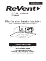
Installation Guide
Read and Save These Instructions
Watch the installation video at:
reventfans.com
Questions? Call
1-877-543-8698 (English) or
1-800-615-5439 (French)
model
RVL80
Need Help?
English

1
Table of Contents
Please Read and Save
These Instructions
page 1
page 1
page 2
page 3
page 4
page 5
page 6
page 7-13
page 13-18
page 18
page 18-19
page 20
Table of Contents
Specifications
What’s Inside The Box
Safety Information
Planning Your Installation
Connecting The Duct
Removing Your Old Fan
SheetLock® Easy Roomside Installation
Installation For New Construction Framing
Care And Cleaning
Frequently Asked Questions
3-Year Limited Warranty
...............
...............
...............
...............
...............
...............
...............
..........
........
.............
........
.............
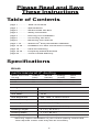
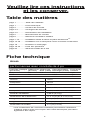
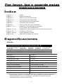
Specifications
Voltage
Frequency
LED Watts
LED Brightness
LED Color Temp
Fan Weight
Shield Size
Housing Length*
Housing Width*
Housing Depth*
120 V
60 Hz
13 W
900, 1000, or 1000 Lumens
2700, 4000, or 5000 Kelvin
5.25 Lbs ( 2.4 Kg )
11 x 11 in ( 27.9 x 27.9 cm )
8 3/8 in ( 21.3 cm )
7 7/8 in ( 20 cm )
5 1/8 in ( 13 cm )
RVL80
*This may require modification of your current opening. Some hand
tools required. Power tools may also be necessary.
performance at 4" ducting
Duct
Size
4 in
4 in
Energy
(watts)
20
19.5
Static Pressure
(in wg)
0.1
0.25
Airow
(cfm)
80
63
Sound
(sones)
0.8

2
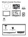
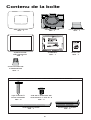
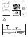
What’s Inside The Box
MANUAL
Qty:1
TEMPLATE
Qty:1
TRIM RING
Qty:1
4” DAMPER
Qty:1
SHORT BRACKET
Qty:2
LONG BRACKET
Qty:1
ROUNDHEAD
WOOD SCREW
Qty:6
#8 x 3/8" BRACKET
SECURING SCREW
Qty:3
USED FOR NEW CONSTRUCTION ONLY
WIRE NUT
Qty:4
FAN
Qty:1
SHIELD
Qty:1
Installation Guide
Read and Save These Instructions
Watch the installation video at:
reventfans.com
Questions? Call
1-877-543-8698 (English) or
1-800-615-5439 (French)
model
RVL80
Need Help?
English

3
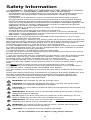
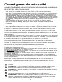
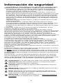
Safety Information
1.) WARNING - TO REDUCE THE RISK OF FIRE, ELECTRIC SHOCK,
OR INJURY TO PERSONS, OBSERVE THE FOLLOWING:
a) Installation work and electrical wiring must be done by qualified person(s) in
accordance with all applicable codes and standards, including fire-rated
construction.
b) Sufficient air is needed for proper combustion and exhausting of gases
through the flue (chimney) of fuel burning equipment to prevent back drafting.
Follow the heating equipment manufacturer's guideline and safety standards,
such as those published by the National Fire Protection Association (NFPA), the
American Society for Heating, Refrigeration and Air Conditioning Engineers
(ASHRAE), and the local code authorities.
c) When cutting or drilling into wall or ceiling, do not damage electrical wiring and
other hidden utilities.
d) Ducted fans must always be vented to the outdoors.
e) If this unit is to be installed over a tub or shower, it must be marked as
appropriate for the application and be connected to a GFCI (Ground Fault Circuit
Interrupter) - protected branch circuit.
2.) Use this unit only in the manner intended by the manufacturer. If you have
questions, contact the manufacturer.
3.) Before servicing or cleaning unit, switch power off at service panel and lock the
service disconnecting means to prevent power from being switched on accidentally.
When the service disconnecting means cannot be locked, securely fasten a
prominent warning device, such as a tag, to the service panel.
4.) This ventilation fan is approved for use over a bathtub or shower when installed
in a GFCI protected circuit. Do not use unapproved fans over a bathtub or shower
that are not approved for that application.
5.) Install ductwork in a straight line with minimal bends.
6.) Use 120 V, 60 Hz for the electrical supply and properly ground the unit. Follow
all local safety and electrical codes.
7.) Do not use this fan with any solid-state control device; such as a dimmer switch.
Solid-state controls may cause harmonic distortion, which can cause a motor
humming noise, as well as increase risk of fire or electric shock.
8.) To reduce the risk of fire or electric shock, do not block air entry shield.
9.) Mount with the lowest moving parts at least 8.2 ft (2.5 m) above floor or grade
level.
10.) Never place a switch where it can be reached from a tub or shower.
11.) Type IC for use in direct contact with thermal insulation not to exceed R-50.
12.) Not for use in cooking areas. (See PAGE 5 for details)
13.) This product must properly connect to the grounding conductor of the supply
circuit.
Follow the heating equipment manufacturer’s guideline and safety standards, such
as those published by the National Fire Protection Association (NFPA), the
American Society for Heating, Refrigeration and Air Conditioning Engineers
(ASHRAE), and the local code authorities.
WARNING: Not suitable for use as a range hood.
CAUTION: For General Ventilating Use Only - Do Not Use To Exhaust
Hazardous Or Explosive Materials And Vapors.
CAUTION: Do not install in locations where the temperature will exceed
104°F (40°C).
IMPORTANT: Exercise care to not damage existing wiring when cutting or
drilling into walls or ceilings.
NOTE: Make sure duct work size is a minimum of the discharge. Do not
reduce. Reducing the duct size can increase fan noise.
IMPORTANT: You may want to consult with a qualified licensed electrician
regarding the wiring of your ventilation fan.
WARNING: To reduce the risk of electric shock, please disconnect the
electrical supply circuit before servicing.
CAUTION: This product must be properly grounded.
Go to reventfans.com to obtain a copy of this manual.

4
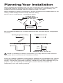
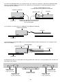
NOTE: If installing in existing construction, you may need to have access to
space above and below the installation location.
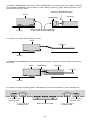
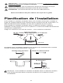
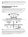
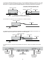
Cooking Area
do not install above or
inside this area
Cooking
Equipment Floor
Turning angle too sharp
Too many elbows
Avoid duct shrink
Elbow near the body
Fan
Body
Minimum 18 in ( 45.72 cm )
Planning Your Installation
When installing the ventilation fan in a new construction site, install the main body
of the FAN and duct work during the rough-in construction of the building. The
SHIELD should be installed after the finished ceiling is in place.
When installing in existing construction, use the provided cutout TEMPLATE for the
ceiling. SHIELD edge should overlap finished ceiling.
Not for use in cooking area - see diagram below.
Do not install ventilation fan in areas where the duct work will require configuration
as shown.
There are multiple installation configurations possible for this ventilation fan. Not all
configurations are shown. If your installation requires a variation other than those
shown, consult with a licensed contractor to determine the best installation for your
project. If you are replacing an existing fan, ensure that the new FAN will
adequately cover the existing opening.

5
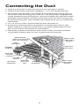
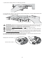
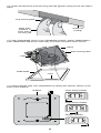
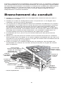
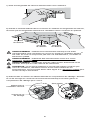
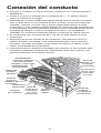
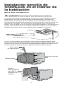
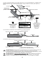
Connecting the Duct
● Install a circular duct to outlet and secure it with duct tape or clamps.
● Install the duct to the outlet with a gradient 1°~2° to the outside as shown.
● The ducting from this FAN to the outside of the building has a strong effect on
● the air flow, noise and energy use of the fan. Use the shortest, straightest duct
● routing possible for best performance, and avoid installing the FAN with smaller
● ducts than recommended. Insulation around the ducts can reduce energy loss
● and inhibit mold growth. Fans installed with existing ducts may not achieve their
● rated airflow.
● 4 in (10.16 cm) round is recommended for best performance.
● Ensure duct joints and exterior penetrations are sealed with caulk or other
● similar material to create an air-tight path, to minimize building heat loss and
● gain, and to reduce the potential for condensation.
● Place/wrap insulation around duct and/or FAN in order to minimize possible
● condensation buildup within the duct, building heat loss and gain.
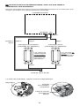
INSULATION*
(Place around and
over Fan Housing.)
Seal gaps
around
housing.
ROUND
DUCT*
POWER
CABLE*
Seal duct
joints with
tape.
FAN
HOUSING
ROUND
ELBOWS*
ROOF CAP*
(with built-in
damper)
Keep duct
runs short.
WALL CAP*
(with built-in
damper)
*Purchase
separately.
OR

6
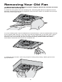
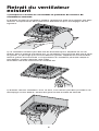
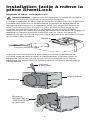
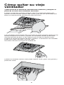
Removing Your Old Fan
1.) Disconnect the electrical power supply and lock out the service
panel for the existing fan.
2.) Remove the grille from the existing fan. Pull the grille down to expose it’s two
springs. Squeeze each spring together and pull down again to release the springs
from the motor plate slots.
3.) Your existing fan may be attached in several ways. Look for attachment screws
in the ceiling and remove. Your fan may also be attached on the attic side, which
will require you to access it from the attic. Locate attic attachment screws and
remove. Fan removal can be the most difficult step, please watch this video:
reventfans.com/how-to-remove-an-old-bath-fan
4.) Remove the old fan. This may require cutting and pulling. Wear gloves and
eye protection.

7
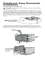
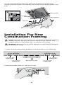
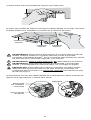
1.) Place the provided sheetrock cutout TEMPLATE on ceiling where you wish the
FAN to be (DAMPER and electrical positions shown on TEMPLATE). We suggest
using painter’s masking tape to hold the template in place while cutting. If there is a
pre-existing fan opening, use aligning windows to find it’s edges. Either cut through
the provided guide slots in the TEMPLATE, or mark your cut lines with a pencil and
remove the TEMPLATE. Use a sheetrock jab saw to cut your fan opening in the
ceiling.
SheetLock® Easy Roomside
Installation
Watch the video: reventfans.com
WARNING: Disconnect all AC Power Breakers or Fuses before attempting
to cut into your ceiling.
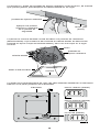
2.) Use a flathead screwdriver to raise the DAMPER away from the notch in the
FAN body, then slide the DAMPER up half way until the notch in the side of the
DAMPER aligns with the upper set of guides. Remove the DAMPER from the FAN.
Remove
DAMPER
from FAN
at notch
flathead
screwdriver
FAN
DAMPER
notch
guide
TEMPLATE
sheetrock jab saw
guide

8
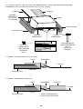
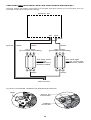
4.) Attach conduit with wiring to FAN.
conduit
FAN
6.) Select a set of holding tabs, depending on the thickness of your sheetrock.
5/8 in (1.6 cm)
holding tab
1/2 in (1.3 cm)
holding tab
final securing tab 5/8 in (1.6 cm)
holding tab
1/2 in (1.3 cm)
holding tab
5.) Reattach DAMPER to FAN inside the ceiling, damper should click into place
securely.
ducting
conduit
DAMPER
FAN
3.) Attach DAMPER to ducting. Tape DAMPER to ducting with duct tape. Set the
connected DAMPER and ducting in the ceiling opening, then set the FAN in the
ceiling opening as well.
ceiling
ducting
Connect DAMPER and
ducting with duct tape
Place FAN and DAMPER
inside CEILING opening
ceiling
ceiling
FAN
DAMPER

9
7.) Bend the holding tabs you selected outward.
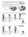
9.) Disconnect FAN motor from electrical enclosure. Remove the electrical cover
set screw and slide open the electrical enclosure.
WARNING: Disconnect the AC power before any work is done to any part of
the circuit ReVent® is connected to. If you do not understand this warning,
seek the services of a qualified licensed electrician.
WARNING: Copper to copper only. Do not use aluminum wire.
WARNING: Follow all local electrical and safety codes, and NEC (National
Electrical Codes).
CAUTION: If your house wires do not match these colors, determine what
each house wire represents before connecting. You may need to consult a
qualified licensed electrician to determine this safely.
8.) Set FAN into place in the opening using holding tabs, now the tabs hold the fan
in position in the ceiling opening.
holding tab
holding tab
holding tab
remove set screw
unplug fan connectors
slide

10
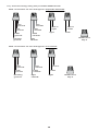
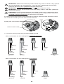
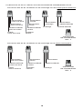
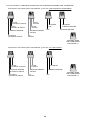
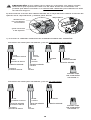
line
ground
line
ground
FAN
ground
housing
ground
line
neutral
line
neutral
FAN
neutral
light
neutral
line in
light
light
line in
FAN
FAN
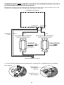
Wire connection for fan and light on separate switches:
WIRE NUT
Qty:4
10.) Connect wiring using the provided WIRE NUTS.
Wire connection for fan and light on one switch:
line
ground
FAN
ground
housing
ground
line
neutral
FAN
neutral
light
neutral
line in
FAN
WIRE NUT
Qty:3
light

11
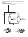
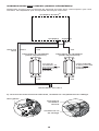
11.) Once connected, reattach the electrical enclosure.
reattach
set screw
plug in fan
connectors
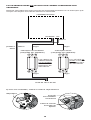
ReVent® fan
fan switch
(purchased separately) light switch
(purchased separately)
120V line AC
black
black
black
white
white
ground
lightfan
black
SWITCHES NOT INCLUDED, USE EXISTING OR MUST BE PURCHASED
SEPARATELY
Always follow all safety instructions included with the switch you purchase. Do not
exceed maximum electrical ratings.
slide
The LED light
can be connected
to a dimmer switch
The FAN wires
cannot be
connected to a
dimmer switch

12
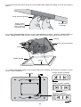
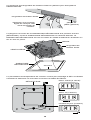
13.) Align TRIM RING notch to vent (DAMPER) position. Attach TRIM RING to
FAN. TRIM RING attaches to FAN body and clicks into place when secure.
14.) Select desired LED color temperature by sliding the selector switch on the
back of the SHIELD.
ceiling
TRIM RING
final securing tabs
notch
12.) Press and bend the final securing tabs flat against ceiling to lock the FAN in
place.
final securing tabs
sheetrock
(ceiling)
apply even
pressure to
each side of
securing tab
FAN
daylight (5000K)
bright white (4000K)
warm white (2700K)
SHIELD

13
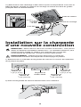
Installation For New
Construction Framing
NOTE: Even with new construction, you can use the SheetLock® installation
method; however, ReVent® can still be installed using a method home
builders would be more familiar with, as outlined in this section.
WARNING: Disconnect all AC Power Breakers or Fuses before attempting
to cut into your ceiling.
1.) Select a set of holding tabs, depending on the thickness of your sheetrock.
2.) Bend the holding tabs you selected outward.
5/8 in (1.6 cm)
holding tab
1/2 in (1.3 cm)
holding tab
final securing tab 5/8 in (1.6 cm)
holding tab
1/2 in (1.3 cm)
holding tab
15.) Connect LED wire to LED plug. Attach the SHIELD by squeezing the
mounting springs together and inserting the springs into the spring guides in the
FAN.
mounting springs
spring guide
LED wire
LED plug

14
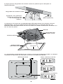
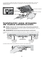
4.) Attach conduit with wiring to FAN.
conduit
DAMPERFAN
DAMPERFAN
5.) Attach DAMPER to ducting.
Attach DAMPER to
ducting with duct tape
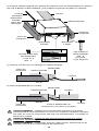
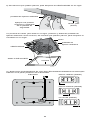
framing joist
framing joist
FAN
SHORT
BRACKET
(can be
cut down)
framing joist
framing joist
SHORT
BRACKET LONG
BRACKET
conduit
3.) Attach FAN to ceiling joists with BRACKETS using ROUNDHEAD WOOD
SCREWS, then install the sheetrock for your ceiling.
ducting
ducting
#8 x 3/8"
BRACKET
SECURING
SCREW
Qty:3
conduit
ROUNDHEAD
WOOD SCREW
Qty:6
(use 2 per
bracket)

15
WARNING: Disconnect the AC power before any work is done to any part of
the circuit ReVent is connected to. If you do not understand this warning,
seek the services of a qualified licensed electrician.
WARNING: Copper to copper only. Do not use aluminum wire.
WARNING: Follow all local electrical and safety codes, and NEC (National
Electrical Codes).
CAUTION: If your house wires do not match these colors, determine what
each house wire represents before connecting. You may need to consult a
qualified licensed electrician to determine this safely.
6.) Disconnect FAN motor from electrical enclosure. Remove the electrical cover
set screw and slide open the electrical enclosure.
remove set screw
unplug fan connectors
slide
line
ground
line
ground
FAN
ground
housing
ground
line
neutral
line
neutral
FAN
neutral
light
neutral
line in
light
light
line in
FAN
FAN
Wire connection for fan and light on separate switches:
WIRE NUT
Qty:4
7.) Connect wiring using the provided WIRE NUTS.
Wire connection for fan and light on one switch:
line
ground
FAN
ground
housing
ground
line
neutral
FAN
neutral
light
neutral
line in
FAN
WIRE NUT
Qty:3
light

16
SWITCHES NOT INCLUDED, MUST BE PURCHASED SEPARATELY
Always follow all safety instructions included with the switch you purchase. Do not
exceed maximum electrical ratings.
ReVent® fan
fan switch
(purchased separately) light switch
(purchased separately)
120V line AC
black
black
black
white
white
ground
lightfan
black
The LED light
can be connected
to a dimmer switch
The FAN wires
cannot be
connected to a
dimmer switch
8.) Once connected, reattach the electrical enclosure.
reattach
set screw
plug in fan
connectors
slide

17
9.) Press and bend the final securing tabs flat against ceiling to lock the FAN in
place.
final securing tabs
sheetrock
(ceiling)
apply even
pressure to
each side of
securing tab
10.) Align TRIM RING notch to vent (DAMPER) position. Attach TRIM RING to
FAN. TRIM RING attaches to FAN body and clicks into place when secure.
ceiling
TRIM RING
final securing tabs
notch
FAN
11.) Select desired LED color temperature by sliding the selector switch on the
back of the SHIELD.
daylight (5000K)
bright white (4000K)
warm white (2700K)
SHIELD

18
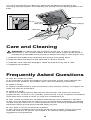
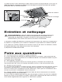
Care and Cleaning
WARNING: To reduce the risk of electric shock, fire, or injury to persons,
disconnect or turn off the breaker and lock the power supply at the panel to
prevent the power from being turned on before servicing or cleaning the unit.
1.) Remove the SHIELD by squeezing the springs and pulling down.
2.) Remove dust and dirt from the FAN with a vacuum cleaner.
3.) Dampen cloth with dish detergent. Wipe the FAN and dry with a cloth.
4.) Replace the SHIELD.
12.) Connect LED wire to LED plug. Attach the SHIELD by squeezing the
mounting springs together and inserting the springs into the spring guides in the
FAN.
mounting springs
spring guide
LED wire
LED plug
Frequently Asked Questions
Q: How do I clean my FAN?
A: It’s important to clean the SHIELD cover from time to time. Dust particles can
build up on the SHIELD. See PAGE 18 for care and cleaning instructions.
Q: What is CFM?
A: CFM is a measurement of air movement (cubic feet per minute). The higher the
CFM, the more air movement.
Q: What is a sone?
A: Sone is the rating used to describe the sound level. The lower the sone the
quieter the fan. A sone is not a decibel. Fans around 1 sone or less are considered
quiet while fans around 2 sones or more are considered loud.
Q: Can I install my bathroom ventilation FAN directly over a bathtub or shower?
A: Yes, but your FAN must be rated for over a shower/bath installation (all ReVent
models are) and must be on a GFCI protected circuit. Consult a qualified licensed
electrician about ground fault protected safety circuits.
Q: Do I have to vent my FAN to the outside?
A: Yes. All spot ventilation fans must be vented to the outside. Follow your local
code and consult it for advice. See PAGE 5 for national venting installation
suggestions and guidelines.

19
Q: Why do the windows and mirrors fog even when the FAN is running?
A: If windows and mirrors are very cold, condensation can still form on those
surfaces. If the bathroom is sealed tightly, replacement air may not be entering the
room fast enough to displace moist air. You need a gap under the bathroom
entrance door to allow air to enter the bathroom. If your home uses 3 inch diameter
ducting, upgrading the duct pipe to 4 inch diameter can greatly increase the airflow.
The vent pipe length should be 10 feet or less with minimal bends (See PAGE 5).
Ensure that the vent pipe is not blocked.
Q: My FAN is operating, but the air is moving slower than normal.
A: Check for obstructions in the ductwork. A common problem is debris blocking the
roof cap or outside wall vent. Older homes may have 3 inch diameter ducting and
changing the duct pipe to 4 inch diameter can greatly increase airflow.
Q: Why is there water dripping from my FAN?
A: Dripping water is typically condensation from a cold vent pipe. Insulating the
ductwork and FAN housing can help solve condensation problems. Running the
FAN longer will ensure moisture is completely removed from the duct. Another
possibility is rain entering the vent pipe through the roof vent opening.
Q: I have installed my FAN and it is not working, what do I do?
A: Make sure the black and white plug-in connector on the FAN is clicked into
place. Check all electrical connections like wire nuts and quick connects. Make
sure the circuit breaker is turned ON after completing all the electrical work. If you
have any concerns consult a licensed electrician.
Q: How do I change the color temperature of the LED light?
A: The color temperature can be adjusted by sliding the selector switch on the back
of the SHIELD (See PAGE 12).
Q: Can the LED light be connected to a dimmer switch?
A: Yes. The LED light can be connected to a dimmer switch, but the dimmer must
be made to work with dimmable LED’s. If you are using a dimmer, you cannot
connect the FAN and LED light together on the dimmer switch. The FAN wires
cannot be connected to a dimmer switch.
Q: I only have 1 switch. Can I wire the LED light and FAN together?
A: Yes. See PAGES 9-11 for instructions on how to do this. However, if you are
using a dimmer, you cannot connect the FAN and LED light together on the dimmer
switch. The FAN wires cannot be connected to a dimmer switch.
Q: I still have additional questions.
A: Contact us at [email protected] or call our service department at
(877) 543-8698. We are happy to assist you with any additional questions.
La page est en cours de chargement...
La page est en cours de chargement...
La page est en cours de chargement...
La page est en cours de chargement...
La page est en cours de chargement...
La page est en cours de chargement...
La page est en cours de chargement...
La page est en cours de chargement...
La page est en cours de chargement...
La page est en cours de chargement...
La page est en cours de chargement...
La page est en cours de chargement...
La page est en cours de chargement...
La page est en cours de chargement...
La page est en cours de chargement...
La page est en cours de chargement...
La page est en cours de chargement...
La page est en cours de chargement...
La page est en cours de chargement...
La page est en cours de chargement...
La page est en cours de chargement...
La page est en cours de chargement...
La page est en cours de chargement...
La page est en cours de chargement...
La page est en cours de chargement...
La page est en cours de chargement...
La page est en cours de chargement...
La page est en cours de chargement...
La page est en cours de chargement...
La page est en cours de chargement...
La page est en cours de chargement...
La page est en cours de chargement...
La page est en cours de chargement...
La page est en cours de chargement...
La page est en cours de chargement...
La page est en cours de chargement...
La page est en cours de chargement...
La page est en cours de chargement...
La page est en cours de chargement...
La page est en cours de chargement...
La page est en cours de chargement...
La page est en cours de chargement...
La page est en cours de chargement...
La page est en cours de chargement...
-
 1
1
-
 2
2
-
 3
3
-
 4
4
-
 5
5
-
 6
6
-
 7
7
-
 8
8
-
 9
9
-
 10
10
-
 11
11
-
 12
12
-
 13
13
-
 14
14
-
 15
15
-
 16
16
-
 17
17
-
 18
18
-
 19
19
-
 20
20
-
 21
21
-
 22
22
-
 23
23
-
 24
24
-
 25
25
-
 26
26
-
 27
27
-
 28
28
-
 29
29
-
 30
30
-
 31
31
-
 32
32
-
 33
33
-
 34
34
-
 35
35
-
 36
36
-
 37
37
-
 38
38
-
 39
39
-
 40
40
-
 41
41
-
 42
42
-
 43
43
-
 44
44
-
 45
45
-
 46
46
-
 47
47
-
 48
48
-
 49
49
-
 50
50
-
 51
51
-
 52
52
-
 53
53
-
 54
54
-
 55
55
-
 56
56
-
 57
57
-
 58
58
-
 59
59
-
 60
60
-
 61
61
-
 62
62
-
 63
63
-
 64
64


