Cisco CW9166I-MR Meraki Ultra-High Performance Access Points Guide d'installation
- Catégorie
- Points d'accès WLAN
- Taper
- Guide d'installation

Meraki
CW9166I‐MR,CW9164I‐MR
HardwareInstallationGuide

Trademarks
Meraki,MerakiCW9166I‐MR,CW9164I‐MR,MerakiCloudController,andMerakiMeshare
trademarksofCiscoSystems,Inc.
Otherbrandandproductnamesareregisteredtrademarksor
trademarksoftheirrespectiveholders.
StatementofConditions
Intheinterestofimprovinginternaldesign,operationalfunction,and/orreliability,CiscoSystemsreservestherightto
make
changestotheproductsdescribedinthisdocumentwithoutnotice.CiscoSystemsdoesnotassumeany
liabilitythatmay
occurduetotheuseorapplicationoftheproduct(s)orcircuitlayout(s)describedherein.
Warranty
Meraki,Inc.providesalifetimewarrantyonthisproduct.Warrantydetailsmaybefoundatwww.meraki.com/legal.

3
TableofContents
1
ScopeofDocumentandRelatedPublications4
2
CW9166I‐MR,CW9164I‐MROverview5
2.1
PackageContents5
2.2
UnderstandingtheCW9166I‐MR,CW9164I‐MR5
2.3
SecurityFeatures7
2.4
EthernetPorts7
2.5
PowerSourceOptions7
2.6
FactoryResetButton7
2.7
LEDIndicatorsandRunDarkMode7
3
Pre‐InstallPreparation8
3.1
ConfigureYourNetworkinDashboard8
3.2
CheckandUpgradeFirmware8
3.3
CheckandConfigureFirewallSettings8
3.4
AssigningIPAddressestoCW9166I‐MR,CW9164I‐MRs9
3.4.1
DynamicAssignment9
3.4.2
Static
Assignment9
3.4.3
StaticIP
AssignmentviaDHCPReservations9
3.5
CollectTools10
3.6
CollectAdditionalHardwareforInstallation10
4
InstallationInstructions11
4.1
ChooseYourMountingLocation11
4.2
InstalltheCW9166I‐MR,CW9164I‐MR11
4.2.1
AttachtheMountPlate11
4.2.1.1
WallorSolid
CeilingMountUsingMountPlate13
4.2.1.2
DropCeiling
MountUsingMountPlate14
4.2.1.3
ElectricalJunctionBoxMountUsingMountPlate18
4.2.2
PowertheCW9166I‐MR,CW9164I‐MR20
4.2.2.1
PoweringtheCW9166I‐MR,CW9164I‐MRwithMerakiACAdapter21
4.2.2.2
PoweringtheCW9166I‐MR,CW9164I‐MRwithMeraki802.3atPoweroverEthernet
Injector21
4.2.2.3
PoweringtheCW9166I‐MR,CW9164I‐MRwithan802.3atPoweroverEthernetSwitch
22
4.2.3
MounttheCW9166I‐MR,CW9164I‐MR22
4.2.3.1
AssembleSecurityHasptotheCW9166I‐MR,CW9164I‐MR22
4.2.3.2
AssembleCW9166I‐MR,CW9164I‐MRtotheMountPlate23
4.2.3.3
DeskorShelfMount25
4.3
SecuretheCW9166I‐MR,CW9164I‐MR26
4.3.1
SecurityScrew26
4.3.2
KensingtonLock26
4.4
VerifyDeviceFunctionalityandTestNetworkCoverage27
5
Troubleshooting27

4
1
ScopeofDocumentandRelatedPublications
TheCW9166I‐MR,CW9164I‐MRHardwareInstallationGuidedescribestheinstallationprocedureforthe
CW9166I‐MR,CW9164I‐MRindooraccesspoint.
Additionalreferencedocumentsareavailableonlineat
www.meraki.com/library/product.

5
2
CW9166I‐MR,CW9164I‐MROverview
TheMerakiCW9166I‐MR,CW9164I‐MRisanenterprise‐class,dual‐concurrent4x4MIMO802.11ax
indooraccesspointdesignedfor
high‐densitydeploymentsinoffices,schools,hospitalsandhotels.
WhenconnectedtotheMerakiCloudController,theCW9166I‐MR,CW9164I‐MRenablesthecreationof
ultra‐highspeed,reliableindoorwirelessnetworksquickly,easilyandcost‐
effectively.
2.1
PackageContents
TheCW9166I‐MR,CW9164I‐MRpackagecontainsthefollowing:
CW9166I‐MR,
CW9164I‐MRaccess
point
Mountingplate
Dropceilingmounting
kit
Wallscrews
Securityscrews
MountingTemplate
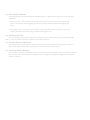
2.2
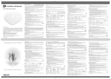
UnderstandingtheCW9166I‐MR,CW9164I‐MR
CW9166I‐MR,CW9164I‐MROperationTemperature:
32°Fto122°F(0°Cto50°C)
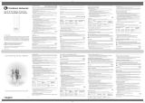
YourMerakiCW9166I‐MR,CW9164I‐MRhasthefollowingfeatures:
Kensingtonlockhardpoint
Mountplateattachmentslots(2x)
Cableaccessbay
Deskmountfeet(4x)withM4*5mmpan‐headscrews
CW9166I‐MR,CW9164I‐MRcableaccessbay
FactoryResetButton
EthernetportPowersuppliedbyPoE:42.5‐57Vdc,0.847‐0.632Aor42.5‐57Vdc,0.776‐0.579A
ACAdapterplug(soldseparately)Powersuppliedbyadapter:54Vdc,0.92A

6
YourCW9166I‐MR,CW9164I‐MRmountplatehasthefollowingfeatures:
Accesspointmountingposts(2x)
Variousmountingholes

7
2.3
SecurityFeatures
TheCW9166I‐MR,CW9164I‐MRfeaturesmultipleoptionsforphysicallysecuringtheaccesspointafter
installation:
1.
Securityscrew–Theaccessorykitincludesscrewsthatcanbeusedtosecuretheaccess
pointto
themountplate.Engagingthesecurityscrewpreventsaccidentaldislodgingand
theft.
2.
Kensingtonlock–Theaccesspointcontainsahardpointthatallowsittobesecuredtoany
nearby
permanentstructureusingastandardKensingtonlock.
2.4
EthernetPorts
TheCW9166I‐MR,CW9164I‐MRfeaturesanEthernetRJ45portthataccepts802.3afpower(labeled
“PoE”).Thisportshould
beusedforuplinktoyourWANconnection.
2.5
PowerSourceOptions
TheCW9166I‐MR,CW9164I‐MRaccesspointcanbepoweredusingeithertheMerakiACAdapteror
802.3afPoEInjector(bothsold
separately)orathird‐party802.3afPoEswitch.
2.6
FactoryResetButton
Ifthebuttonispressedandheldforatleastfivesecondsandthenreleased,theCW9166I‐MR,CW9164I‐
MRwillrebootandbe
restoredtoitsoriginalfactorysettingsbydeletingallconfigurationinformation
storedontheunit.

8
3
Pre‐InstallPreparation
Youshouldcompletethefollowingstepsbeforegoingon‐sitetoperformaninstallation.
3.1
ConfigureYourNetworkinDashboard
ThefollowingisabriefoverviewonlyofthestepsrequiredtoaddanCW9166I‐MR,CW9164I‐MRtoyour
network.Fordetailed
instructionsaboutcreating,configuringandmanagingMerakiwirelessnetworks,
refertotheMerakiCloud
ControllerManual(meraki.com/library/product).
1.
Logintohttp://dashboard.meraki.com.Ifthisisyourfirsttime,createanewaccount.
2.
FindthenetworktowhichyouplantoaddyourAPsorcreateanewnetwork.
3.
AddyourAPstoyournetwork.YouwillneedyourMerakiordernumber(foundonyourinvoiceif
youordereddirectlyfromMeraki)ortheserialnumberofeachAP,whichlookslikeQxxx‐xxxx‐xxxx,
andis
foundonthebottomoftheunit. YouwillalsoneedyourEnterpriseCloudControllerlicensekey,which
youshouldhavereceivedviaemailfromshipping@meraki.com.
4.
Gotothemap/floorplanviewandplaceeachAPonthemapbyclickinganddraggingittothe
location
whereyouplantomountit.
3.2
CheckandUpgradeFirmware
ToensureyourCW9166I‐MR,CW9164I‐MRperformsoptimallyimmediatelyfollowinginstallation,Meraki
recommendsthatyoufacilitateafirmwareupgradepriortomountingyourCW9166I‐MR,CW9164I‐MR.
1.
AttachyourCW9166I‐MR,CW9164I‐MRtopowerandawiredInternetconnection.Seep.19of
thisHardwareInstallation
Guidefordetails.
2.
TheCW9166I‐MR,CW9164I‐MRwillturnonandthePowerLEDwillglowsolidorange.Iftheunitdoes
notrequireafirmware
upgrade,thePowerLEDwillturnwhitewithinthirtyseconds.
* Iftheunitrequiresanupgrade,thePowerLEDwillbeginblinkingorangeuntiltheupgradeis
complete,
atwhichpointthePowerLEDwillturnsolidwhite.Youshouldallowaboutanhourforthe
firmware
upgradetocomplete,dependingonthespeedofyourinternetconnection.
3.3
CheckandConfigureFirewallSettings
Ifafirewallisinplace,itmustallowoutgoingconnectionsonparticularportstoparticularIP
addresses.
ThemostcurrentlistofoutboundportsandIPaddressescanbefoundhere:
http://tinyurl.com/y79une3

9
3.4
AssigningIPAddressestoCW9166I‐MR,CW9164I‐MRs
AllgatewayCW9166I‐MR,CW9164I‐MRs(CW9166I‐MR,CW9164I‐MRswithEthernetconnectionstothe
LAN)mustbeassignedroutableIPaddresses.
TheseIPaddressescanbedynamicallyassignedviaDHCP
orstaticallyassigned.
3.4.1
DynamicAssignment
WhenusingDHCP,theDHCPservershouldbeconfiguredtoassignastaticIPaddressforeachMAC
address
belongingtoaMerakiAP.Otherfeaturesofthewirelessnetworksuchas802.1xauthentication,
mayrelyonthe
propertythattheAPshavestaticIPaddresses.
3.4.2
StaticAssignment
StaticIPsareassignedusingthelocalwebserveroneachAP.Thefollowingproceduredescribeshowto
set
thestaticIP:
1.
Usingaclientmachine(e.g.alaptop),connecttotheAPeitherwirelessly(byassociatingtoany
SSID
broadcastbytheAP)oroverawiredconnection.
Ifusingawiredconnection,connecttheclientmachinetotheCW9166I‐MR,CW9164I‐MReitherthrough
aPoEswitchoraMeraki
PoEInjector.IfusingaPoEswitch,pluganEthernetcableintotheCW9166I‐MR,
CW9164I‐MR’sEthernetjack,andtheotherend
intoaPoEswitch.Thenconnecttheclientmachineover
EthernetcabletothePoEswitch.IfusingaMeraki
PoEInjector,connecttheCW9166I‐MR,CW9164I‐MR
tothe“PoE”portoftheInjector,andtheclientmachinetothe“LAN”port.
2.
Usingawebbrowserontheclientmachine,accesstheAP’sbuilt‐inwebserverby
browsingto
http://my.meraki.com.Alternatively,browsetohttp://10.128.128.128.
3.
Clickonthe“StaticIPConfiguration”tab. Login. Thedefaultusernameis“admin”. Thedefault
passwordis
theAP’sserialnumber,withhyphensincluded
4.
ConfigurethestaticIPaddress,netmask,gatewayIPaddressandDNSserversthatthisAPwilluse
onits
wiredconnection.
5.
Ifnecessary,reconnecttheAPtotheLAN.
3.4.3
StaticIPviaDHCPReservations
InsteadofassociatingtoeachMerakiAPindividuallytoconfigurestaticIPaddresses,anadministratorcanassign
staticIPaddressesontheupstreamDHCPserver.Through“DHCPreservations”,IPaddressesare“reserved”
forthe
MACaddressesoftheMerakiAPs.PleaseconsultthedocumentationfortheDHCPservertoconfigure
DHCP
reservations.

10
3.5
CollectTo ols
Youwillneedthefollowingtoolstoperformaninstallation:
Phillips
screwdrive
r
HammerDrillwith1/4”
(6.3mm)
bits
3.6
CollectAdditionalHardwareforInstallation
802.3atPoEpowersource(either
PoE
switchorMeraki802.3atPoE
Injector)
ACAdapter
NetworkcableswithRJ45connectorslong
enoughforyourparticularmounting
location
or

11
4
InstallationInstructions
4.1
ChooseYourMountingLocation
AgoodmountinglocationisimportanttogettingthebestperformanceoutofyourCW9166I‐MR,
CW9164I‐MRaccesspoint.
Keepthefollowinginmind:
1.
Thedeviceshouldhaveunobstructedlineofsighttomostcoverageareas.Forexample,if
installing
inanofficefilledwithworkspacesdividedbymid‐heightcubiclewalls,installingonthe
ceilingorhigh
onawallwouldbeideal.
2.
PoweroverEthernetsupportsamaximumcablelengthof300ft(100m).
3.
Ifbeingusedinameshdeployment,theCW9166I‐MR,CW9164I‐MRshouldhavelineofsighttoat
leasttwootherMeraki
devices.Formoredetailedinstructionsregardingaccesspointlocation
selection,referencetheMeraki
NetworkDesignGuide(meraki.com/library/product).
4.2
InstalltheCW9166I‐MR,CW9164I‐MR
Formostmountingscenarios,theCW9166I‐MR,CW9164I‐MRmountplateprovidesaquick,simple,and
flexiblemeansofmounting
yourdevice.Theinstallationshouldbedoneintwosteps.First,installthemount
platetoyourselectedlocation.
Then,attachtheCW9166I‐MR,CW9164I‐MRtothemountplate.
!!!Thisequipmentisonlysuitableformountingatheights≤2m!!!
4.2.1
AttachtheMountPlate
TheCW9166I‐MR,CW9164I‐MRmountplatecanbeusedtoinstallyouraccesspointinawiderangeof
scenarios:wallorsolid
ceiling,belowadropceiling,onvariouselectricaljunctionboxes,oraboveadrop
ceiling(intheplenum).
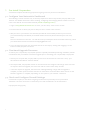
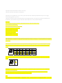
Themountplatecontainsavarietyofholepatternsthatarecustomizedforeachinstallationscenario.The
mountingtemplate(includedinboxwithmountplate)shouldbeusedtodrillholesforwallmountsandalso
to
identifythecorrectholepatternsinthemountplatethatshouldbeusedforeachtypeofmount.
Thefollowingimagesalsoshowtheholepatternsthatshouldbeusedforeachtypeofmount:

12
4.2.1.1
WallorSolidCeilingMountUsingMountPlate
Usingincludedscrews,attachthemountplatetoyourmountingwallorceiling.
ItisrecommendedthattheCW9166I‐MR,CW9164I‐MRbemountedtoawallorsolidceilingusingthe
mountplateforphysical
securityreasons.
If mounting your CW91661-MR to a wall, skip to “Power the CW91661-MR“ on P. 20

13
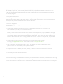
4.2.1.2
ElectricalJunctionBoxMountUsingMountPlate
TheCW9166I‐MR,CW9164I‐MRcanbemountedtoa4”squarecablejunctionbox,a3.5or4”round
cablejunctionbox,or
variousU.S.andEuropeanoutletboxes(mountingscrewsarenotincluded).
Usingappropriatemountinghardwareforyourspecifictypeofjunctionbox,attachthemount
4.2.2
PowertheCW9166I‐MR,CW9164I‐MR
Ifmountingtoanelectricaljunctionbox,feedtheEthernetcablethroughthecableaccessholeintheMount
Plate.
Ifmountingtoawallorceiling,theEthernetcablewillfeedthroughthecableslotonbottomoftheCW9166I‐
MR,CW9164I‐MR.

14
4.2.2.1
PoweringtheCW9166I‐MR,CW9164I‐MRwiththeMerakiACAdapter(soldseparately)
1.
PlugthepowercordintotheCW9166I‐MR,CW9164I‐MRandtheotherendintoawalloutlet.
2.
PluganEthernetcablethatisconnectedtoanactiveEthernetconnectionintotheEth0portonthe
CW9166I‐MR,CW9164I‐MR.
4.2.2.2
PoweringtheM410‐MRwiththeMeraki802.3atPoweroverEthernetInjector(sold
separately)
1.
PlugthepowercordintothePoEInjectorandtheotherendintowallpower.
2.
PluganEthernetcablethatisconnectedtoanactiveEthernetconnectionintothe“IN“portonthe
injector.
3.
RouteEthernetcablefromthe“OUT“portontheinjectortotheEth0portinthecablebayofthe
CW9166I‐MR,CW9164I‐MR.

15
4.2.2.3
PoweringtheCW9166I‐MR,CW9164I‐MRwithan802.3atPoweroverEthernetSwitch
RouteEthernetcablefromaportonanactive802.3atPoEswitchtotheEth0portinthebayofthe
CW9166I‐MR,CW9164I‐MR.
4.2.3
MounttheCW9166I‐MR,CW9164I‐MR
The CW91661-MR is Gigabit Ethernet-capable. To maximize device performance, a
Gigabit-capable
switch should be used.

20
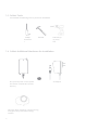
4.2.3.2
AssembleCW9166I‐MR,CW9164I‐MRtotheMountPlate
(Thissectionappliestowalland/orsolidceiling,dropceilingorelectricaljunctionboxmount
whereyouhavealreadyinstalledthemountplate.)
Insertthetoplatchonthemountplateintothetopmountplateattachmentslotsonthebackofthedevice.
Rotatethe
bottomoftheunitintothebottommountplateattachmentslot.Theunitwillclickintoplace.

21
4.2.3.3
DeskorShelfMount
TheCW9166I‐MR,CW9164I‐MRcanbeplacedonadeskorshelfrestingonthenon‐scratchrubber
feet.Themountplateis
notnecessaryforadeskorshelfmounting.

22
4.3
SecuretheCW9166I‐MR,CW9164I‐MR
Dependingonyourmountingenvironment,youmaywanttosecuretheCW9166I‐MR,CW9164I‐MRtoitsmount
location.YourCW9166I‐MR,CW9164I‐MR
canbesecuredinseveralways.IftheCW9166I‐MR,CW9164I‐MRhasbeeninstalledusingthemountplate,it
canbesecuredviasecurity
screw(TorxandPhilipsheadsecurityscrewsareincluded;chooseone),and/or
Kensingtonlock.Ifthemount
platewasnotused,theCW9166I‐MR,CW9164I‐MRcanstillbesecuredusingaKensingtonlock.
4.3.1
SecurityScrew
Installthesecurityscrewinthelowermountplatetab.
4.3.2
KensingtonLock
AttachaKensingtonlockcabletotheaccesspointatthehardpointonthesideofthedevice.
Attachtheotherendofthecabletoasecurelocation,suchasapipeorbuildingfixture.

23
4.4
VerifyDeviceFunctionalityandTestNetworkCoverage
1.
CheckLEDs
The LEDshouldbesolidwhite.Ifitisflashingorange,thefirmwareisautomaticallyupgradingand
the
LEDshouldturngreenwhentheupgradeiscompleted(normallyinunderthirtyminutes).
Note:YourCW9166I‐MR,CW9164I‐MRmusthaveanactiveroutetotheInternettocheckandupgradeits
firmware.
2.
Verifyaccesspointconnectivity
Useany802.11clientdevicetoconnecttotheCW9166I‐MR,CW9164I‐MRandverifyproperconnectivityusing
theclient’swebbrowser.
3.
Checknetworkcoverage
Confirmthatyouhavegoodsignalstrengththroughoutyourcoveragearea.Youcanusethesignalstrength
meter
onalaptop,smartphone,orotherwirelessdevice.
5
Troubleshooting
ReferencetheMerakiknowledgebaseathttp://meraki.com/support/knowledge_baseforadditionalinformation
and
troubleshootingtips.
6
Regulatory
FCCComplianceStatement
Thisdevicecomplieswithpart15oftheFCCrules.Operationissubjecttothefollowingtwoconditions:(1)Thisde‐
vicemaynotcauseharmfulinterference,and(2)thisdevicemustacceptanyinterferencereceived,including
interference
t
hatmaycauseundesiredoperation.
FCCInterferenceStatement
ThisequipmenthasbeentestedandfoundtocomplywiththelimitsforaClassBdigitaldevice,pursuanttopart15
of
theFCCRules.Theselimitsaredesignedtoprovidereasonableprotectionagainstharmfulinterferenceina
residen
tial
installation.Thisequipmentgenerates,usesandcanradiateradiofrequencyenergyand,ifnotinstalled
andusedin
accordancewiththeinstructions,maycauseharmfulinterferencetoradiocommunications.However,
thereisno
guaranteethatinterferencewillnotoccurinaparticularinstallation.Ifthisequipmentdoescause
harmfulinterference
toradioortelevisionreception,whichcanbedeterminedbyturningtheequipmentoffand
on,theuserisencouraged
tocorrecttheinterferencebyoneofthefollowingmeasures:
•Reorientorrelocatethereceivingantenna.
•Increasetheseparationbetweentheequipmentandreceiver.
•Connecttheequipmentintoanoutletonacircuitdifferentfromwhichthereceiverisconnected.
•Consultthedealeroranexperiencedradio/TVtechnicianforhelp.
FCCCaution
AnychangesormodificationsnoexpresslyapprovedbyMerakicouldvoidtheuser’sauthoritytooperatethis
equipment.ThisTransmittermustnotbeco‐locatedoroperationinconjunctionwithanyotherantennaor
transmitter.
FCCRadiationExposureStatement
ThisequipmentcomplieswithFCCradiationexposurelimitssetforthforanuncontrolledenvironment.This
equipment
shouldbeinstalledandoperatedwithminimumdistance41cmbetweentheradiatorandyourbody.

24
Thistransmitter
mustnotbeco‐locatedoroperatinginconjunctionwithanyotherantennaortransmitter.
IEEE802.11bor802.11goperationofthisproductintheUSAisfirmware‐limitedtochannels1through11.
FCCregulationsrestricttheoperationofthisdevicetoindooruseonly.
Theoperationofthisdeviceisprohibitedonoilplatforms,cars,trains,boats,andaircraft,exceptthatoperationofthis
deviceispermittedinlargeaircraftwhileflyingabove10,000feet.
Operationoftransmittersinthe5.925‐7.125GHzbandisprohibitedforcontroloforCommunicationswithunmanned
aircraftsystems.
Professionalinstallationisrequired
La page est en cours de chargement...
La page est en cours de chargement...
La page est en cours de chargement...
-
 1
1
-
 2
2
-
 3
3
-
 4
4
-
 5
5
-
 6
6
-
 7
7
-
 8
8
-
 9
9
-
 10
10
-
 11
11
-
 12
12
-
 13
13
-
 14
14
-
 15
15
-
 16
16
-
 17
17
-
 18
18
-
 19
19
-
 20
20
-
 21
21
-
 22
22
-
 23
23


Cisco CW9166I-MR Meraki Ultra-High Performance Access Points Guide d'installation
- Catégorie
- Points d'accès WLAN
- Taper
- Guide d'installation
dans d''autres langues
Documents connexes
Autres documents
-
Meraki MR24 Hardware Installation Manual
-
 Software s identifiD Device Onboarding Mode d'emploi
-
-
Cisco Meraki MT11-HW Guide d'installation
-
 Cambium Networks XV2-2 Manuel utilisateur
-
Extron WAP 100AC Manuel utilisateur
-
-
-
Cambium Networks XV2-2 VWi-Fi 6 Manuel utilisateur
-
 Cambium Networks XV2-2T Manuel utilisateur


