Hilti GX 2 Manuel utilisateur
- Catégorie
- Outils électroportatifs
- Taper
- Manuel utilisateur
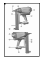
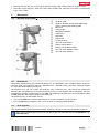
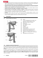
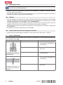
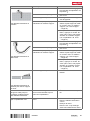
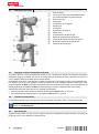
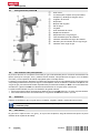
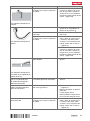
Ci-dessous, vous trouverez de brèves informations pour cloueur GX 2. Ce cloueur à gaz est conçu pour enfoncer des fixations (clous) appropriées dans le béton, l'acier, la maçonnerie en blocs de béton, les blocs de béton silico-calcaires, la maçonnerie enduite et autres matériaux appropriés à l'utilisation de la technique de fixation directe. Le cloueur est destiné à un usage manuel uniquement et doit être utilisé avec les batteries Li-ion Hilti B12/2.6 ou B 12-30 et les chargeurs de la série C 4/12-50. Le cloueur est équipé d'un guide-clou, d'un réglage de la profondeur d'enfoncement, d'un crochet de ceinture, d'une gâchette de sécurité et d'un indicateur d'état de la cartouche de gaz et de la batterie.
Ci-dessous, vous trouverez de brèves informations pour cloueur GX 2. Ce cloueur à gaz est conçu pour enfoncer des fixations (clous) appropriées dans le béton, l'acier, la maçonnerie en blocs de béton, les blocs de béton silico-calcaires, la maçonnerie enduite et autres matériaux appropriés à l'utilisation de la technique de fixation directe. Le cloueur est destiné à un usage manuel uniquement et doit être utilisé avec les batteries Li-ion Hilti B12/2.6 ou B 12-30 et les chargeurs de la série C 4/12-50. Le cloueur est équipé d'un guide-clou, d'un réglage de la profondeur d'enfoncement, d'un crochet de ceinture, d'une gâchette de sécurité et d'un indicateur d'état de la cartouche de gaz et de la batterie.


-
 1
1
-
 2
2
-
 3
3
-
 4
4
-
 5
5
-
 6
6
-
 7
7
-
 8
8
-
 9
9
-
 10
10
-
 11
11
-
 12
12
-
 13
13
-
 14
14
-
 15
15
-
 16
16
-
 17
17
-
 18
18
-
 19
19
-
 20
20
-
 21
21
-
 22
22
-
 23
23
-
 24
24
-
 25
25
-
 26
26
-
 27
27
-
 28
28
-
 29
29
-
 30
30
-
 31
31
-
 32
32
-
 33
33
-
 34
34
-
 35
35
-
 36
36
-
 37
37
-
 38
38
-
 39
39
-
 40
40
-
 41
41
-
 42
42
-
 43
43
-
 44
44
-
 45
45
-
 46
46
-
 47
47
-
 48
48
-
 49
49
-
 50
50
-
 51
51
-
 52
52
-
 53
53
-
 54
54
-
 55
55
-
 56
56
-
 57
57
-
 58
58
-
 59
59
-
 60
60


Hilti GX 2 Manuel utilisateur
- Catégorie
- Outils électroportatifs
- Taper
- Manuel utilisateur
Ci-dessous, vous trouverez de brèves informations pour cloueur GX 2. Ce cloueur à gaz est conçu pour enfoncer des fixations (clous) appropriées dans le béton, l'acier, la maçonnerie en blocs de béton, les blocs de béton silico-calcaires, la maçonnerie enduite et autres matériaux appropriés à l'utilisation de la technique de fixation directe. Le cloueur est destiné à un usage manuel uniquement et doit être utilisé avec les batteries Li-ion Hilti B12/2.6 ou B 12-30 et les chargeurs de la série C 4/12-50. Le cloueur est équipé d'un guide-clou, d'un réglage de la profondeur d'enfoncement, d'un crochet de ceinture, d'une gâchette de sécurité et d'un indicateur d'état de la cartouche de gaz et de la batterie.
dans d''autres langues
- English: Hilti GX 2 User manual
- español: Hilti GX 2 Manual de usuario
- português: Hilti GX 2 Manual do usuário