GE AZ9VH12EAC Le manuel du propriétaire
- Catégorie
- Climatiseurs split-system
- Taper
- Le manuel du propriétaire
Ce manuel convient également à

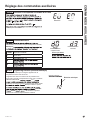
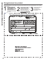
Write the model and serial
numbers here:
Model # _________________
Serial # _________________
You can find them on a label on
the top panel.
GE is a trademark of the General Electric Company. Manufactured under trademark license.
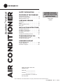
AIR CONDITIONER
Zoneline® Vertical
49-5000640 Rev. 2 10-23
SAFETY INFORMATION . ........3
FEATURES OF THE ZONELINE
Temperature Control . . ............... . .4
About your Heat Pump .................4
Quick Heat Recovery .................. .4
CARE AND CLEANING
Air Filters .............................5
Drain . . ...............................5
Indoor/Outdoor Coils ................ . .5
Base Pan ............................ .5
INSTALLATION INSTRUCTIONS
Installation Overview . ..................6
Installation Preparation ................ 15
Installing the Zoneline ................. 18
Servicing ........................... 24
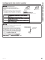
Setting the Auxiliary Controls . ........ .25
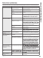
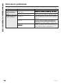
TROUBLESHOOTING TIPS
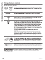
Normal Operating Sounds .......... . . 30
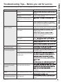
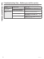
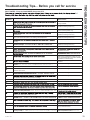
Troubleshooting Tips .................. 31
CONSUMER SUPPORT
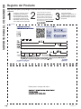
Product Registration ................ . 34
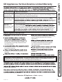
Limited Warranty .....................35
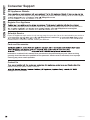
Consumer Support ................... 36
OWNER’S MANUAL
AND INSTALLATION
INSTRUCTIONS
Heat Pump
AZ9VH

249-5000640 Rev. 2
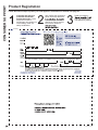
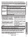
THANK YOU FOR CHOOSING GE APPLIANCES.
Whether you grew up with GE Appliances, or this is your first, we’re happy to have you in the family.
We take pride in the craftsmanship, innovation and design that goes into every GE Appliances
product, and we think you will too. Among other things, registration of your appliance ensures that we
can deliver important product information and warranty details when you need them.
Register your GE appliance now online. Helpful websites and phone numbers are available in the
Consumer Support section of this Owner’s Manual. You may also mail in the pre-printed registration
card included in the back of this manual.

49-5000640 Rev. 2 3
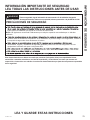
READ AND SAVE THESE INSTRUCTIONS
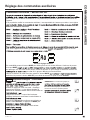
IMPORTANT SAFETY INFORMATION
READ ALL INSTRUCTIONS BEFORE USING THE APPLIANCE
SAFETY INFORMATION
WARNING For your safety, the information in this manual must be followed to minimize the risk of fire, explosion, electric shock,
property damage, personal injury, or loss of life.
SAFETY PRECAUTIONS
NOTE: GE Appliances strongly recommends that any servicing be performed by a qualified person.
product with refrigerants, check with the company handling disposal about what to do.
with this refrigerant. DO NOT use equipment certified for R22 refrigerant only.
This appliance is not intended for use by persons (including children) with reduced physical, sensory or mental capabilities, or lack
of experience and knowledge, unless they have been given supervision or instruction concerning use of the appliance by a person
responsible for their safety.
WARNING Para su seguridad, siga la información de este manual a fin de minimizar riesgos de incendio, explosión, descargas
eléctricas, daños en su propiedad, lesiones personales o la pérdida de la vida.
PRECAUCIONES DE SEGURIDAD
manual.
NOTA:
del mismo.
Este electrodoméstico no deberá ser usado por personas (incluyendo niños) con capacidades físicas, sensoriales o mentales
reducidas o con falta de experiencia y conocimiento, a menos que cuenten con supervisión o instrucción con relación al uso de este
electrodoméstico por parte de una persona responsable de su seguridad.
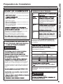
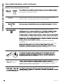
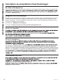
WARNING Pour votre sécurité, veuillez observer les consignes de ce manuel afin de réduire le risque d’incendie, d’explosion, de
choc électrique, de dommages à la propriété ou de blessures graves ou fatales.
MESURES DE SÉCURITÉ
REMARQUE
en la matière.
Cet appareil n’est pas destiné à être utilisé par des personnes (y compris les enfants) dont les capacités physiques, sensorielles ou
mentales sont réduites ou l’expérience et les connaissances sont insuffisantes, sauf si une personne responsable de leur sécurité les
surveille étroitement ou les familiarise avec l’utilisation de l’appareil.

49-5000640 Rev. 2
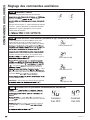
FEATURES OF THE ZONELINE
Features
About Your Heat Pump
Heat pumps can save money by removing heat from the
outside air—even when the outside temperature is below
pump, don’t change the room thermostat by more than
one degree at one time. Raising the heat setting 2–3
elements in order to reach the new temperature setting
quickly.
heat pumps and cost more to operate.
setting to prevent short cycling.
compressor cycles off.
When the outdoor temperature is determined to be too
cold, heat is provided by the electric heater instead of by
the heat pump.
Temperature Control
wall mounted heating and cooling thermostat, minimum
2C/2H. Standard thermostats used on prior models are
instructions of the thermostat being used on how to
control the unit.
Quick Heat Recovery
Activates each time the thermostat is switched from OFF or COOL mode to HEAT
Do Not Operate the Air Conditioner (cool mode) in Freezing Outdoor Conditions

49-5000640 Rev. 2 5
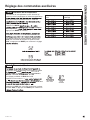
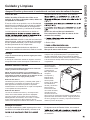
Air Filters
NOTICE: Do not operate the Zoneline without the
filter in place. If a filter becomes torn or damaged, it
should be replaced immediately.
Operating without the filter in place or with a damaged
filter will allow dirt and dust to reach the indoor coil and
reduce the cooling/heating, performance, airflow, and
efficiency of the unit.
Dirty filters reduce cooling, heating performance and air
flow.
Changing the filter will: Decrease cost of operation,
save energy, prevent clogged heat exchanger coils, and
reduce the risk of premature component failure.
Replacement filters should be purchased from your local
retailer where air conditioner and furnace accessories
with 2" filter.
NOTE: Use only one filter in the installation.
To replace the filter (unit mounted return air filter):
2. Remove the filter.
To maintain optimum performance, change the filter
at least every 30 days. For other filter installation
options, see page 7.
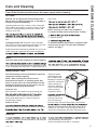
CARE AND CLEANING
Care and Cleaning
Drain
Clean the drain system regularly to prevent clogging.
area. Check the unit condensate drain periodically. Keep
it free of anything that may block or impeded the flow of
matter in the drainpipe, it should be removed and cleaned.
Indoor/Outdoor Coils
The Indoor/Outdoor coils on the Zoneline should be
cleaned and checked regularly.
NOTE: When cleaning the coils do not use
acid-based coil cleaners, or cleaning agents with
formic or acetic acids. Care must be taken to avoid
bending the aluminum fins on the coils. Do not use
any high pressure spray mechanisms.
Indoor-Air Coil
Minor amounts of lint and dirt may pass through the
accumulations can be carefully vacuumed away
with a brush attachment on a vacuum cleaner or
professionally cleaned.
Outdoor-Air Coil
paths must remain clear. Check the outdoor-air exhaust
outdoor-air intake
should also be kept
free of obstructions.
Blocking the outdoor-air
exhaust or outdoor-air
intake opening will
reduce the efficiency
of your unit and could
cause premature
compressor failure.
of the outdoor-air
coils may require the
unit to be removed
from the closet. See servicing section of this manual
cleaning is recommended for the inside surface of the
outdoor coil. Use care to cover and protect electrical
controls and components during the cleaning process.
Base Pan
into the unit from the outside and settle in the base pan may be present in the base pan.
Check it periodically and clean, if necessary.
Outdoor coils
Have the coils cleaned regularly.
Turn off the Zoneline and disconnect the power supply before cleaning.

49-5000640 Rev. 2
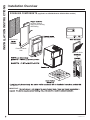
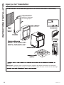
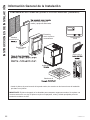
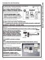
Installation Overview
INSTALLATION INSTRUCTIONS
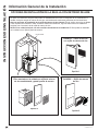
ZONELINE COMPONENTS (applicable on AZ9VH12DAC & AZ9VH12EAC models)
the plenum.
IMPORTANT:
Architectural
structural support.
Apply proper caulking
and flashing.
Exterior/Outside
Wall
or
and level plenum.
Return Air Grille
or

49-5000640 Rev. 2 7
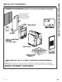
ZONELINE COMPONENTS (applicable on AZ9VH12DBM & AZ9VH12EBM models)
the plenum.
IMPORTANT:
Architectural
Return Air Grille
structural support.
Apply proper caulking
and flashing.
Exterior/Outside
Wall
D x 233 3 H
and level plenum.
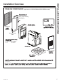
Installation Overview
INSTALLATION INSTRUCTIONS

49-5000640 Rev. 2
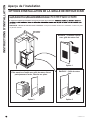
arrangements will cause performance problems.
There are three indoor return air grille installation options. Choose the option that best suits your
installation details.
NOTE: For the main unit, use only one inlet filter in the installation.
in the access panel/door.
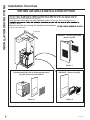
Installation Overview
RETURN AIR GRILLE INSTALLATION OPTIONS
Unit-mounted filter with a field-supplied return
air grille and access door/panel
Option 3
RAVRG2* – Return air grille
Option 2
Filter
Filter
Outside wall
RAVRG4* – Access panel with
return air grille
Option 1
Filter
INSTALLATION INSTRUCTIONS

49-5000640 Rev. 2
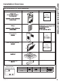
INSTALLATION INSTRUCTIONS
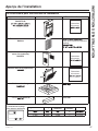
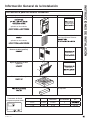
ACCESSORIES for NEW Installation
Accessory and model number Appearance Cutout Dimensions
Plenum (telescoping)
Cutout
Dimensions:
Architectural Louver
Access Panel with Return Air
Grille (optional)
Cutout
Dimensions:
Return Air Grille (optional) 22 2
22 2
Cutout
Dimensions:
Drain Platform Not Applicable
Not applicable
Wall Thermostat
(appearance may vary)
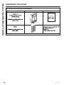
Installation Overview
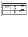
Model Type Wiring Thermostat Type Fan Speed(s) Kit Number
2C/2H 2
2-Way 5-wire 2-Way 2

49-5000640 Rev. 2
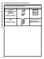
ACCESSORIES for NEW Installation
Accessory and model number Appearance Cutout Dimensions
Plenum (telescoping)
Cutout
Dimensions:
Architectural Louver
Installation Overview
INSTALLATION INSTRUCTIONS

49-5000640 Rev. 2
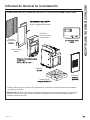
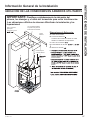
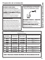
IMPORTANT: Plan and locate plenum, drains and thermostat
cable carefully to avoid interference. Hard-to-reach locations will make
installation and service difficult!
Reference Dimensions
A.
B. Electrical connections -
Direct connections using flex cable or
appropriate wiring
C. Case width: 23
D. Case depth:
E.
F. Condensate drains:
approximately 3 from left case wall
and 3
3
G. Makeup air duct height: 7"
D
E
F
B
A
G
C
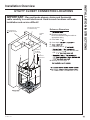
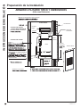
Installation Overview
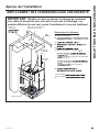
INSTALLATION INSTRUCTIONS
UTILITY CLOSET CONNECTION LOCATIONS
Secondary
Drain
Electrical
Disconnect
Conduit
for direct
connection
Outside
Wall
Use rigid duct for
bends and tees
Flex duct may be used
for transitions only

49-5000640 Rev. 2
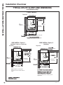
Installation Overview
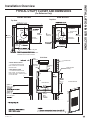
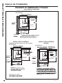
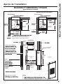
INSTALLATION INSTRUCTIONS
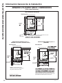
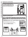
TYPICAL UTILITY CLOSET AND DIMENSIONS
(For Reference Only)
FRONT INSTALL
Top View
13 ½”
7.16”
10” duct
minimum
clearance
Connection
Unit
Front
clearance
Electrical
Connection
minimum
Door/access panel return air grille
Note:
additional space around the unit to ease
installation and access for service.
Top View
SIDE INSTALL Option 1
(RAVRG2* in Door or closet wall)
13 ½”
7.16”
10” duct
Connection
Electrical
Connection
clearance
minimum
clearance
Unit
Front clearance
Field Supplied
minimum
NOTE: Clearance and minimum
dimensions are from interior walls of
closet
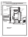
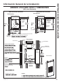
Top View
13 ½”
7.16”
10” duct
Connection
Electrical
Connection
clearance
minimum
clearance
Unit
Front clearance
access panel
minimum
SIDE INSTALL Option 2
(RAVRG4*)
closet rear wall to
per instructions, slide rear of unit through
unit is facing the wall plenum. Follow
remaining instructions for installing unit to
wall plenum.

49-5000640 Rev. 2
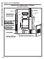
Installation Overview
INSTALLATION INSTRUCTIONS
TYPICAL UTILITY CLOSET AND DIMENSIONS
(For Reference Only)
FRONT INSTALL
Top View
minimum
clearance
Connection
Unit
Front
clearance
Electrical
Connection
Duct
minimum
Door/access panel return air grille
additional space around the unit to ease
installation and access for service.
Top View
SIDE INSTALL
Connection
Electrical
Connection
clearance
Duct
minimum
clearance
Unit
Front
clearance
Door/access
panel
minimum
A
B
B - Minimum recommended access door height: 57
Side View
• FRONT INSTALLATION
– 3" minimum clearance from
front of case and 3" minimum
from two sides
• SIDE INSTALLATION
– 5" minimum clearance from
front of case, 3" minimum from
access side and 3" minimum from
non-access side.
Option 1
Return air grille
Option 2
Access panel with
return air grille
Outside wall
Field supplied
flashing
cutout
32" H x Exterior/Outside
Wall
Unit
Filter Bracket
Secure
Drain
Air
discharge
outlet
Flexible or
rigid duct
Rigid
ductwork

49-5000640 Rev. 2
Installation Overview
TYPICAL UTILITY CLOSET AND DIMENSIONS
(For Reference Only)
additional space around the unit to ease
installation and access for service.
A
B
B - Minimum recommended access door height: 57
Side View
• FRONT INSTALLATION
– 3" minimum clearance from
front of case and 3" minimum
from two sides
• SIDE INSTALLATION
Option 2
Access panel with return air grille
front of
minimum from non-access side
Outside wall
Field supplied
flashing
cutout Exterior/Outside
Wall
Unit
Filter
Bracket
Secure Drain
Air
discharge
outlet
Flexible or
rigid duct
Rigid
ductwork
Option 1
field supplied closet door, open width >
7"
INSTALLATION INSTRUCTIONS

49-5000640 Rev. 2
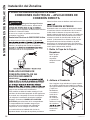
INSTALLATION INSTRUCTIONS
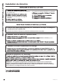
Installation Preparation
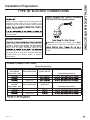
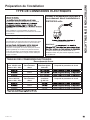
TYPE OF ELECTRIC CONNECTIONS
A power supply kit must be used to supply power to the
Models must be installed using the appropriate GE
Appliances power supply kit for the branch circuit
amperage and the electrical resistance heater wattage
select the appropriate kit.
connection of components is done in accordance with
electrical codes.
Power Supply Kit Direct Connect
208/230/265 Volt Applications
MPORTANT: Connection to a branch circuit MUST
be done by direct connection in accordance with the
building mounted exposed receptacle is not permitted
by code.
POWER CONNECTION CHART
Direct Connections
Power Supply Kits
230 / 208 Volt
Range: 187v - 254v
Configuration
Direct Connection
Heater Wattage
@ 230 / 208 Volt
Circuit Protective Device
Hard Wired
Hard Wired
Hard Wired
Power Supply Kits
265 Volt*
Range: 249v - 293v
Configuration
Direct Connection
Heater Wattage
@ 265 Volt
Circuit Protective Device
Hard Wired
Hard Wired
Hard Wired
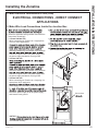
External Disconnect
supply located within line of sight of the closet door
means shall be readily accessible while the air
shall not obscure the rating plate or be located on
the access panel or closet door. A properly rated field
supplied switch is a common means for electrical
disconnection.

49-5000640 Rev. 2
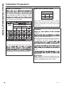
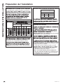
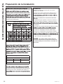
Installation Preparation
Ductwork
to the case.
all fittings, registers and/or diffusers.
DO NOT operate unit without a supply duct attached.
For installations that require a ducted return, the
with no bends, turns, contractions, or expansions.
this page. Use these charts to select your fan speed
setting.
static pressure.
NOTICE: Flex duct can collapse and cause
airflow restrictions. Do not use flex duct for 90°
bends or unsupported runs of 5 ft. or more.
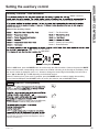
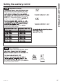
Indoor Air Flow Data
then using the chart below to determine the actual
airflow. Under no circumstances should the Zoneline
unit be operated to an ESP in excess of .3” W.C..
in inadequate air flow thus leading to poor performance
and/or premature component failure.
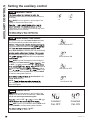
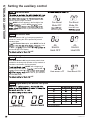
Fan Boost Mode
ON 77 OFF 78
High
CFM
Medium
CFM
Medium
CFM CFM
333
*
Your airflow should be balanced based on many factors,
you can calculate the CFM using the above chart.
Indoor Air Flow Data (cont)
Higher CFMs tend to increase Sensible capacity,
enhance room circulation and increase duct noise,
while lower CFMs tend to increase latent capacity and
reduce noise.
CFM Recommendations
AZ9VH12
500 433 363
•
• = Recommended Mid Range
INSTALLATION INSTRUCTIONS

49-5000640 Rev. 2
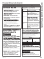
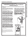
Installation Preparation
IMPORTANT ELECTRICAL
SAFETY—READ
CAREFULLY
WARNING
RISK OF ELECTRIC SHOCK.
installed by a qualified electrician.
local codes and ordinances.
must be properly grounded.
the nameplate of each unit.
• Do not use an extension cord with this unit.
• Aluminum building wiring may present special
problems—consult a qualified electrician.
• When the unit is not running there is still voltage to
the electrical controls.
• Disconnect the power to the unit before servicing by:
circuit breakers off at the panel.
2. Disconnecting the power cord from the unit.
BEFORE YOU BEGIN
Read these instructions completely and carefully.
• IMPORTANT – Save these
instructions for local inspector’s use.
• IMPORTANT – Observe all governing
codes and ordinances.
• Note to Installer – Be sure to leave these
instructions with the owner.
•
Note to Owner – Keep these instructions for
future reference.
•
shall not be accessible to the general public.
•
covered under the Warranty.
•
•
installation procedures as described in these
instructions when installing this air conditioner.
Questions? Call 844-GE4-PTAC (or 844-434-7822 ) or Visit our Website at: GEAppliances.com
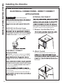
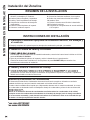
ELECTRICAL
REQUIREMENTS
NOTE: All field wiring must comply with NEC and
local codes. It is the responsibility of the installer
to ensure that the electrical codes are met.
Use ONLY
for single outlet branch circuit
Fuse/Circuit
Breaker
current protection to the units is the
responsibility of the owner.
Grounding
circuit to unit, or through separate
ground wire provided on permanently
connected units. Be sure that branch
circuit is grounded.
in tables and install a single branch
circuit. All wiring must comply with
local and national codes.
NOTE: Use copper conductors
only.
WARNING
RISK OF ELECTRIC SHOCK.
properly grounded.
outlet branch circuit.
of the owner.
NOTE: Use copper conductors only.
Recommended Branch Circuit Wire Sizes*
Nameplate
Maximum Circuit
Breaker Size
AWG Wire Size**
AWG - American Wire Gauge
C
INSTALLATION INSTRUCTIONS

49-5000640 Rev. 2
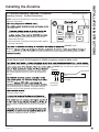
Installing the Zoneline
1.
locations.
2.
3.
4. Complete condensate drain connections.
5.
6. Connect the top ductwork.
7. Connect the remote thermostat.
8. Connect auxiliary features, if required.
9. Make electrical connections to unit.
10.
11. Review the final installation checklist.
12.
13.
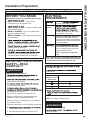
INSTALLATION SUMMARY
1. Plan for proper electrical supply, drains and ductwork locations.
1. Complete rough in plumbing for primary and secondary condensation drains.
2. Install the Louver and Wall Plenum
1.
Refer to instructions included in the louver kit RAVAL4 or RAVAL3 for proper installation procedures.
2.
Refer to instructions included in the wall plenum kit RAVWPT15B for proper installation procedures.
INSTALLATION INSTRUCTIONS
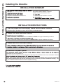
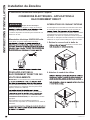
3. Install and Level the Drain Platform
1.
Condensate Disposal System
condensate onto the hot outdoor coil.
When high outdoor humidity prevents the slinger from disposing of all condensate, the excess condensate overflows
NOTE: If the primary drain system fails to remove all of the condensate from the unit, any excess condensate
will overflow from the drain pan into the secondary drain (if connected), and drain outside the building. This
is your indication that the chassis or drain requires servicing.
INSTALLATION INSTRUCTIONS

49-5000640 Rev. 2
INSTALLATION INSTRUCTIONS
Installing the Zoneline
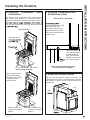
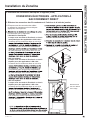
4. Complete Condensate Drain
Connections
An external or an internal drain must be attached to
the primary drain connector. A secondary drain is
supplied if required by state and local codes. Refer to
the secondary drain is not used, seal its drain port with
Drain Overview
Internal Drain (Primary)
Secondary Drain
Run condensate line to
building interior drain
line with proper venting
according to local
building codes.
Option for drain line
connection to right of
platform
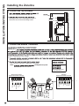
4. Complete Condensate Drain
Connections (cont)
External Drain (Secondary)
Refer to drain platform instruction
manual for drain installation
secondary drain line though
the plenum and grille.
Use a pipe connector and
additional piping to ensure
drain pipe extends past the
outdoor grille.
Extend secondary
drain pipe into plenum
or through outdoor
grille. Grille must be
modified to allow drain
line to pass through.
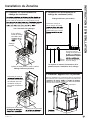
Drain
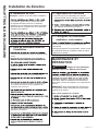
5. Install Unit to Wall Plenum
Align the unit with plenum opening and slide unit
toward plenum to ensure it is seated properly with the
drain platform. Ensure that unit is secure and level in
all directions.
Unit
Wall
Drain
Option for drain line
connection to front of
platform
Front or side primary drain options

49-5000640 Rev. 2
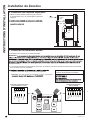
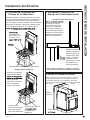
6. Connect the Top Ductwork
1.
duct to the rigid ductwork above the unit.
2.
discharge outlet. Use a field supplied clamp to
secure the duct to the air discharge outlet.
Installing the Zoneline
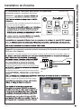
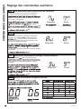
7. Connect the Remote Thermostat
IMPORTANT:
all wires in building from line voltage.
1.
connect the thermostat to the unit.
2.
• Use connector required for applicable thermostat.
• Note: GE Appliances part#
WJ26X28997 can be ordered.
Maximum Wiring
Connection to the Unit
AWG – American Wire Gauge
Use only Class 2 wiring
Air
Discharge
Outlet
Flexible or
Rigid Ductwork
Rigid
Ductwork
INSTALLATION INSTRUCTIONS
Standard
External Thermostat Connector
7 8
C W Y
LG HG
R
Yellow
Black
White
Blue
Tan
Green
Red
Y2
Light blue
6 5 4 3 2 1
B
2-Way Communication
External Thermostat Connector
RS
485
Brown
5
B-
White/Blue
3
C
Black
2
R
Red
1
Blue
4
A+
La page charge ...
La page charge ...
La page charge ...
La page charge ...
La page charge ...
La page charge ...
La page charge ...
La page charge ...
La page charge ...
La page charge ...
La page charge ...
La page charge ...
La page charge ...
La page charge ...
La page charge ...
La page charge ...
La page charge ...
La page charge ...
La page charge ...
La page charge ...
La page charge ...
La page charge ...
La page charge ...
La page charge ...
La page charge ...
La page charge ...
La page charge ...
La page charge ...
La page charge ...
La page charge ...
La page charge ...
La page charge ...
La page charge ...
La page charge ...
La page charge ...
La page charge ...
La page charge ...
La page charge ...
La page charge ...
La page charge ...
La page charge ...
La page charge ...
La page charge ...
La page charge ...
La page charge ...
La page charge ...
La page charge ...
La page charge ...
La page charge ...
La page charge ...
La page charge ...
La page charge ...
La page charge ...
La page charge ...
La page charge ...
La page charge ...
La page charge ...
La page charge ...
La page charge ...
La page charge ...
La page charge ...
La page charge ...
La page charge ...
La page charge ...
La page charge ...
La page charge ...
La page charge ...
La page charge ...
La page charge ...
La page charge ...
La page charge ...
La page charge ...
La page charge ...
La page charge ...
La page charge ...
La page charge ...
La page charge ...
La page charge ...
La page charge ...
La page charge ...
La page charge ...
La page charge ...
La page charge ...
La page charge ...
La page charge ...
La page charge ...
La page charge ...
La page charge ...
La page charge ...
La page charge ...
La page charge ...
La page charge ...
-
 1
1
-
 2
2
-
 3
3
-
 4
4
-
 5
5
-
 6
6
-
 7
7
-
 8
8
-
 9
9
-
 10
10
-
 11
11
-
 12
12
-
 13
13
-
 14
14
-
 15
15
-
 16
16
-
 17
17
-
 18
18
-
 19
19
-
 20
20
-
 21
21
-
 22
22
-
 23
23
-
 24
24
-
 25
25
-
 26
26
-
 27
27
-
 28
28
-
 29
29
-
 30
30
-
 31
31
-
 32
32
-
 33
33
-
 34
34
-
 35
35
-
 36
36
-
 37
37
-
 38
38
-
 39
39
-
 40
40
-
 41
41
-
 42
42
-
 43
43
-
 44
44
-
 45
45
-
 46
46
-
 47
47
-
 48
48
-
 49
49
-
 50
50
-
 51
51
-
 52
52
-
 53
53
-
 54
54
-
 55
55
-
 56
56
-
 57
57
-
 58
58
-
 59
59
-
 60
60
-
 61
61
-
 62
62
-
 63
63
-
 64
64
-
 65
65
-
 66
66
-
 67
67
-
 68
68
-
 69
69
-
 70
70
-
 71
71
-
 72
72
-
 73
73
-
 74
74
-
 75
75
-
 76
76
-
 77
77
-
 78
78
-
 79
79
-
 80
80
-
 81
81
-
 82
82
-
 83
83
-
 84
84
-
 85
85
-
 86
86
-
 87
87
-
 88
88
-
 89
89
-
 90
90
-
 91
91
-
 92
92
-
 93
93
-
 94
94
-
 95
95
-
 96
96
-
 97
97
-
 98
98
-
 99
99
-
 100
100
-
 101
101
-
 102
102
-
 103
103
-
 104
104
-
 105
105
-
 106
106
-
 107
107
-
 108
108
-
 109
109
-
 110
110
-
 111
111
-
 112
112


GE AZ9VH12EAC Le manuel du propriétaire
- Catégorie
- Climatiseurs split-system
- Taper
- Le manuel du propriétaire
- Ce manuel convient également à
dans d''autres langues
- English: GE AZ9VH12EAC Owner's manual
- español: GE AZ9VH12EAC El manual del propietario
Documents connexes
-
GE AZ95H12EAC Mode d'emploi
-
GE AZ75H18DAC Owner's Manual and Installation Instructions
-
GE AZ91H18E2E Le manuel du propriétaire
-
-
GE Zoneline AZ91H18E3C Le manuel du propriétaire
-
GE AZ91H18D3C Le manuel du propriétaire
-
-
GE AZ91H09E5CW1 Le manuel du propriétaire