Kichler Lighting 49933WZC Manuel utilisateur
- Taper
- Manuel utilisateur

Date Issued: 10/13/17 IS-49933-CB
We’re here to help 866-558-5706
Hrs: M-F 9am to 5pm EST
CAUTION – RISK OF SHOCK –
Disconnect Power at the main circuit breaker panel or main fuse
box before starting and during the installation.
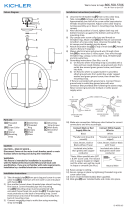
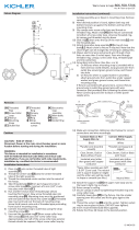
1) Take threaded tube[14] and thread on two hexnuts[15] and
thread into main assembly[1] as shown.
2) Place decorative ring[13] on top of main assembly. Next place
top[12] onto the decorative ring as shown and secure into
place using the open nial[11].
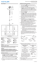
3) Take threaded pipe[5] from parts bag and screw in screw
collar loop[9] a minimum of 6 mm (1/4”). Lock into place with
hexnut[6].
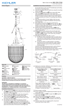
4) Run another hexnut down threaded nipple almost touching
rst hexnut. Now screw threaded pipe into mounting strap[2].
Mounting strap must be positioned with extruded thread faced
into outlet box[4]. Threaded nipple must protrude out the back
of mounting strap. Screw third hexnut onto end of threaded
nipple protruding from back of mounting strap.
5) Connect mounting strap to outlet box using mounting strap
screws[3].
6) Unscrew the threaded ring[8] from screw collar loop. Take
canopy[7] and pass over screw collar loop. Approximately
one half of the screw collar loop exterior threads should be
exposed. Adjust screw collar loop by turning assembly up or
down in mounting strap. Remove canopy.
7) After desired position is found, tighten both top and bottom
hexnuts up against the bottom and top of the mounting strap.
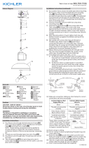
8) Slip canopy over screw collar loop and thread on threaded
ring. Attach chain[10] (with xture connected) to bottom of
screw collar loop. Unscrew threaded ring, let canopy and
threaded ring slip down. Attach chain to xture if required.
9) Weave electrical wire and ground wire through chain links no
more than 3 inches apart. Pass wire through threaded ring,
canopy, screw collar loop, threaded pipe and into outlet box.
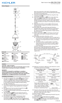
10) Grounding instructions: (See Illus. A or B).
A) On xtures where mounting strap is provided with a
hole and two raised dimples. Wrap ground wire from
outlet box around green ground screw, and thread into
hole.
B) On xtures where a cupped washer is provided. Attach
ground wire from outlet box under cupped washer and
green ground screw, and thread into mounting strap.
If xture is provided with ground wire. Connect xture ground
wire to outlet box ground wire with wire connector. (Not pro-
vided.) After following the above steps. Never connect ground
wire to black or white power supply wires.
11) Make wire connections (connectors not provided.) Reference
chart below for correct connections and wire accordingly.
GREEN GROUND
SCREW
CUPPED
WASHER
OUTLET BOX
GROUND
FIXTURE
GROUND
DIMPLES
WIRE CONNECTOR
OUTLET BOX
GROUND
GREEN GROUND
SCREW
FIXTURE
GROUND
A
B
14
15
13
16
7
2
6
8
9
10
12
5
4
3
11
1
Connect Black or
Red Supply Wire to:
Connect
White Supply Wire to:
Black White
*Parallel cord (round & smooth)
*Parallel cord (square & ridged)
Clear, Brown, Gold or Black
without tracer
Clear, Brown, Gold or Black
with tracer
Insulated wire (other than green)
with copper conductor
Insulated wire (other than green)
with silver conductor
*Note: When parallel wires (SPT I & SPT II)
are used. The neutral wire is square shaped
or ridged and the other wire will be round in
shape or smooth (see illus.)
Neutral Wire
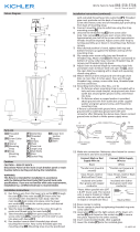
12) Raise canopy to ceiling.
13) Secure canopy in place by tightening threaded ring onto screw
collar loop.
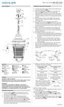
14) Install glass[16] by sliding up from the bottom of glass cage
and seat into the inside bottom of cage as shown. Next bend
over the tabs above the glass to secure into place. Repeat for
all the glass panels.
15) Insert recommended bulb (Not supplied).

INSTRUCTIONS
For Assembling and Installing Fixtures in Canada
Pour L’assemblage et L’installation Au Canada
Nous sommes là pour vous aider 866-558-5706
Heures : du lundi au vendredi, de 9h à 17h (heure de l’Est)
ATTENTION – RISQUE DE DÉCHARGES ÉLECTRIQUES -
Couper le courant au niveau du panneau du disjoncteur du
circuit principal ou de la boîte à fusibles principale avant de
procéder à l’installation.
Date Issued: 10/13/17 IS-49933-CB
1) Prendre le tube leté [14] et visser sur deux hexagones [15] et
visser dans l’ensemble principal [1] comme indiqué.
2) Placez la bague décorative [13] sur le dessus de l’assemblage
principal. Placez ensuite le dessus [12] sur l’anneau décoratif
comme indiqué et xez-le en place en utilisant le euron ouvert
[11].
3) Sortir le tube leté[5] du sac des pièces et visser la boucle
dans une boucle de collier[9] à vis à un minimum de 6 mm (1/4
po). Bloquer avec l’écrou hexagonal[3].
4) Visser un autre écrou hexagonal sur le tube leté jusqu’à ce
qu’il entre pratiquement en contact avec le premier écrou
hexagonal. Visser maintenant le tube leté dans la bride de
montage[2]. La bride de montage doit être placée avec le let
extrudé faisant face à la boîte à prises[4]. Le tube leté doit
sortir de l’arrière de la bride de montage. Visser le troisième
écrou hexagonal sur l’extrémité du tube leté sortant de
l’arrière du support de montage.
5) Connectez la sangle de montage à la boîte de sortie à l’aide
des vis de xation de la sangle[3].
6) Dévisser la bague letée de boucle de col vissé[8]. Prendre la
canopée et passer la boucle de col vissé.[7] Environ la moitié
de la boucle de col de vis, letage extérieur doit être exposées.
Régler boucle de col vissé en tournant l’Assemblée vers le haut
ou vers le bas à une courroie de xation. Enlevez le baldaquin.
7) Lorsque la position désirée est trouvée, la serrer hexnuts haut
et en bas vers le haut contre le bas et en haut de la sangle de
xation.
8) Habillage feuillet sur boucle de col vissé et vissez-le sur la
bague letée. Fixer la chaîne[10] (avec l’appareil connecté) en
bas de la boucle de col vissé. Maillon de la chaîne étroite se
termine à l’aide de pinces de chaîne ou rembourré de pinces
pour éviter tout dommage à la n. Dévisser la bague letée,
décevrons pas couvert et glissement de l’anneau leté.
9) Tissent le l électrique et l de terre par l’intermédiaire de
chaîne relie pas plus de 3 pouces de distance. Passer le l à
travers la bague letée, verrière, boucle de col vissé, tige letée
et dans la boîte de sortie.
10) Connecter les ls. Se porter au tableau ci-dessous pour faire
les connexions.
11) Placer le cache au plafond.
12) Fixer le cache en serrant la bague letée sur le collier-écrou.
13) Installez la vitre [6] en glissant vers le haut depuis le bas de la
cage en verre et insérez-la dans le fond intérieur de la cage,
comme indiqué. Ensuite, pliez les languettes au-dessus du
verre pour les xer en place. Répétez l’opération pour tous les
panneaux de verre.
14) Installer la ou les ampoules recommandées (non fournies).
14
15
13
16
7
2
6
8
9
10
12
5
4
3
11
1
Connecter le fil noir ou
rouge de la boite
Connecter le fil blanc de la boîte
A Noir A Blanc
*Au cordon parallèle (rond et lisse)
*Au cordon parallele (à angles droits el strié)
Au bransparent, doré, marron, ou
noir sans fil distinctif
Au transparent, doré, marron, ou
noir avec un til distinctif
Fil isolé (sauf fil vert) avec
conducteur en cuivre
Fil isolé (sauf fil vert) avec
conducteur en argent
*Remarque: Avec emploi d’un fil paralléle
(SPT I et SPT II). Le fil neutre est á angles
droits ou strié et l’autre fil doit étre rond ou
lisse (Voir le schéma).
Fil Neutre
-
 1
1
-
 2
2


Kichler Lighting 49933WZC Manuel utilisateur
- Taper
- Manuel utilisateur
dans d''autres langues
Documents connexes
-
 Kichler Lighting 44029NI Manuel utilisateur
-
 Kichler Lighting 49791AUB Manuel utilisateur
-
 Kichler Lighting 42376BK Manuel utilisateur
-
 Kichler Lighting 44022NBR Manuel utilisateur
-
 Kichler Lighting 43011NBR Manuel utilisateur
-
 Kichler Lighting 44034NI Manuel utilisateur
-
 Kichler Lighting 44290WWW Manuel utilisateur
-
 Kichler Lighting 44303WZC Manuel utilisateur
-
 Kichler Lighting 49939WZC Manuel utilisateur
-
 Kichler Lighting 43984BK Manuel utilisateur


