
1) TURN OFF POWER.
IMPORTANT: Before you start, NEVER attempt any work
without shutting off the electricity until the work is done.
a) Go to the main fuse, or circuit breaker, box in your
home. Place the main power switch in the “OFF”
position.
b) Unscrew the fuse(s), or switch “OFF” the circuit breaker
switch(s), that control the power to the fixture or room that
you are working on.
c) Place the wall switch in the “OFF” position. If the fixture
to be replaced has a switch or pull chain, place those in
the “OFF” position.
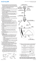
2) Find the appropriate threaded holes on mounting strap.
Assemble mounting screws into threaded holes.
3) Attach mounting strap to outlet box. (Screws not provided)
Mounting strap can be adjusted to suit position of fixture.
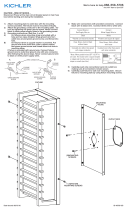
4) Grounding instructions: (See Illus. A or B).
A) On fixtures where mounting strap is provided with a
hole and two raise dimples. Wrap ground wire from
outlet box around green ground screw, and thread into
hole.
B) On fixtures where a cupped washer is provided. Put
ground wire from outlet box under cupped washer and
green ground screw and thread screw into hole in
mounting strap.
If fixture is provided with ground wire. Connect fixture
ground wire to outlet box ground wire with wire connector,
(not provided) after following the above steps. Never
connect ground wire to black or white power supply wires.
GREEN GROUND
SCREW
CUPPED
WASHER
A
B
OUTLET BOX
GROUND
FIXTURE
GROUND
DIMPLES
WIRE CONNECTOR
(NOT PROVIDED)
OUTLET BOX
GROUND
GREEN GROUND
SCREW
FIXTURE
GROUND
Connect Black or
Red Supply Wire to:
Connect
White Supply Wire to:
Black White
*Parallel cord (round & smooth) *Parallel cord (square & ridged)
Clear, Brown, Gold or Black
without tracer
Clear, Brown, Gold or Black
with tracer
Insulated wire (other than green)
with copper conductor
Insulated wire (other than green)
with silver conductor
*Note: When parallel wires (SPT I & SPT II)
are used. The neutral wire is square shaped
or ridged and the other wire will be round in
shape or smooth (see illus.)
Neutral Wire
Date Issued: 10/16/15 IS-7772-US
We’re here to help 866-558-5706
Hrs: M-F 9am to 5pm EST
SEE OTHER SIDE FOR SPANISH TRANSLATIONS.
VEA EL OTRO LADO DE TRADUCCIONES AL ESPAÑOL.
MOUNTING STRAP
PLANCHA PARA MONTAR
FIXTURE
ARTEFACTO
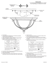
5) Make wire connections (connectors not provided.) Reference
chart below for correct connections and wire accordingly.
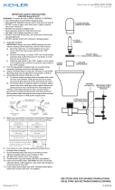
6) Push fixture to ceiling, carefully passing mounting screws
through holes.
7) Screw threaded balls onto mounting screws. Tighten threaded
balls to secure fixture to ceiling.
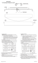
8) Raise glass with ring up to fixture. Pass hole in glass over
socket.
9) Slip spacer over socket.
10) Attach socket ring to socket ring tool.
11) Raise socket ring tool with socket ring attached up to
fixture. Pass socket ring tool with socket ring attached
through hole in glass. Thread socket ring onto socket.
Tighten socket ring to secure glass in place. (DO NOT over
tighten.)
THREADED BALL
BOLA ROSCADO
SOCKET RING
ANILLO DEL CASQUILLO
SOCKET RING TOOL
HERRAMIENTA DEL ANILLO
DEL CASQUILLO
SPACER
ESPACIADOR
GLASS
VIDRIO

5) Haga las conexiones de alambres (No se provee conectores).
Vea la tabla de referencia de abajo para las conexiones
correctas y los alambres correspondientes.
6) Empuje el artefacto al cielo raso pasando cuidadosamente
los tornillos de montaje a través de los agujeros.
7) Atornille las bolas roscado en los tornillos de montaje. Ariete
las bolas roscados para sujetar el artefacto a la cielo.
8) Eleve la vidrio con el anillo hacia el artefacto. Pasando el
agujero en el vidrio encima del casquillo.
9) Deslice el espaciador sobre el casquillo.
10) Acople el anillo del casquillo a la herramienta del anillo del
casquillo.
11) Baje la herramienta del anillo del casquillo con el anillo del
casquillo acoplado abajo a través del vidrio. Rosque el anillo
del casquillo al casquillo. Apriete el anillo del casquillo para
sujetar el vidrio en el lugar. (NO apriete excesivamente.)
1) APAGAR LA ALIMENTACIÓN DE ENERGIE ELÈTRICA.
IMPORTANTE: Antes de comenzar, NUNCA trate de trabajar
sin antes desconectar la corriente hasta que el trabajo se
termine.
a) Vaya a la caja principal de fusibles, o interruptor o caja
de circuitos de su casa. Coloque el interruptor de la
corriente principal en posición de apagado “OFF”.
b) Desatornille el (los) fusible (s), o coloque el interruptor o
interruptores del breaker en posición de apagado “OFF”,
que controla (n) la corriente hacia el artefacto o habitación
donde está trabajando.
c) Coloque el interruptor de pared en posición de apagado
“OFF”. Si el artefacto que se va a reemplazar tiene un
interruptor o cadena que se jala, colóquelos en la
posición de apagado “OFF”.
2) Encuentre los agujeros roscados apropiados en la abrazadera
de montaje. Monte los tornillos de montaje en los agujeros
roscados.
3) Acople la abrazadera de montaje a la caja de salida. (No se
provee tornillos). La abrazadera de montaje se puede ajustar
para acomodar la posición del artefacto.
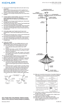
4) Instrucciones de conexión a tierra (Vea la ilustración A o B)
A) En artefactos donde se provee la abrazadera de
montaje con un agujero y dos depresiones onduladas:
Envuelva el alambre de tierra de la caja de salida
alrededor del tornillo de tierra verde y rosque en el
agujero.
B) En artefactos donde se provee una arandela cóncava.
Acople el alambre de tierra de la caja de salida debajo de
la arandela cóncava y del tornillo de tierra verde, y
rosque el tornillo en la abrazadera de montaje.
Si el artefacto está provisto con alambre de tierra: Conecte
el alambre de tierra del artefacto con el alambre de tierra de
la caja de salida con un conector de alambre. (No se provee.)
Date Issued: 10/16/15 IS-7772-US
We’re here to help 866-558-5706
Hrs: M-F 9am to 5pm EST
ARANDELA
CONCAVA
A
B
TIERRA DE LA
CAJA DE SALIDA
TORNILLO DE TIERRA,
VERDE
DEPRESIONES
TIERRA
ARTEFACTO
CONECTOR DE ALAMBRE
(NO SE PROVEE)
TIERRA DE LA
CAJA DE SALIDA
TORNILLO DE TIERRA,
VERDE
TIERRA
ARTEFACTO
Conectar el alambre de
suministro negro o rojo al
Conectar el alambre de
suministro blanco al
Negro Blanco
*Cordon paralelo (redondo y liso)
*Cordon paralelo (cuadrado y estriado)
Claro, marrón, amarillio o negro
sin hebra identificadora
Claro, marrón, amarillio o negro
con hebra identificadora
Alambre aislado (diferente del verde)
con conductor de cobre
Alambre aislado (diferente del
verde) con conductor de plata
*Nota: Cuando se utiliza alambre paralelo
(SPT I y SPT II). El alambre neutro es de forma
cuadrada o estriada y el otro alambre será de
forma redonda o lisa. (Vea la ilustracíón).
Hilo Neutral
SEE OTHER SIDE FOR ENGLISH TRANSLATIONS.
VEA EL OTRO LADO DE TRADUCCIONES AL INGLÉS.
MOUNTING STRAP
PLANCHA PARA MONTAR
FIXTURE
ARTEFACTO
THREADED BALL
BOLA ROSCADO
SOCKET RING
ANILLO DEL CASQUILLO
SOCKET RING TOOL
HERRAMIENTA DEL ANILLO
DEL CASQUILLO
SPACER
ESPACIADOR
GLASS
VIDRIO

1) TURN OFF POWER.
IMPORTANT: Before you start, NEVER attempt any work
without shutting off the electricity until the work is done.
a) Go to the main fuse, or circuit breaker, box in your
home. Place the main power switch in the “OFF”
position.
b) Unscrew the fuse(s), or switch “OFF” the circuit breaker
switch(s), that control the power to the fixture or room that
you are working on.
c) Place the wall switch in the “OFF” position. If the fixture
to be replaced has a switch or pull chain, place those in
the “OFF” position.
2) Find the appropriate threaded holes on mounting strap.
Assemble mounting screws into threaded holes.
3) Attach mounting strap to outlet box. (Screws not provided)
Mounting strap can be adjusted to suit position of fixture.
4) Make wire connections (connectors not provided.) Reference
chart below for correct connections and wire accordingly.
5) Push fixture to ceiling, carefully passing mounting screws
through holes.
6) Screw threaded balls onto mounting screws. Tighten threaded
balls to secure fixture to ceiling.
7) Raise glass with ring up to fixture. Pass hole in glass over
socket.
8) Slip spacer over socket.
9) Attach socket ring to socket ring tool.
10) Raise socket ring tool with socket ring attached up to
fixture. Pass socket ring tool with socket ring attached
through hole in glass. Thread socket ring onto socket.
Tighten socket ring to secure glass in place. (DO NOT over
tighten.)
1) COUPER L’ALIMENTATION SECTEUR.
IMPORTANT: TOUJOURS couper l’électricité avant de
commencer le travail.
a) Localiser le coffret à fusibles ou le disjoncteur du
domicile. Mettre l’interrupteur principal en position
d’Arrêt.
b) Dévisser le ou les fusibles (ou mettre le disjoncteur sur
Arrêt) qui contrôlent l’alimentation vers le luminaire ou la
pièce dans laquelle le travail est effectué.
c) Mettre l’interrupteur mural en position d’Arrêt. Si le luminaire
à remplacer est doté d’un interrupteur ou d’une chaîne
connectée à l‘interrupteur, placer ces éléments en
position d’Arrêt.
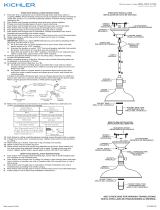
2) Trouver les trous filetés appropriés sur le support de
montage. Visser les vis de montage dans les trous taraudés.
3) Fixer le support de montage sur la boîte à prises. (Vis non
fournies). Le support de montage peut être réglé afin de
positionner correctement le luminaire.
4) Connecter les fils (connecteurs non fournis). Se porter au
tableau ci-dessous pour faire les connexions.
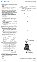
5) Pousser le luminaire vers le plafond en passant soigneusement
les vis de montage par les trous.
6) Visser lles boules filetés sur l’extrémité des vis de montage.
Serrerles boules filetés pour fixer le luminaire au plafond.
7) Soulever le verre avec la bague au luminaire. Passer le trou du
verre sur la douille.
8) Glisser l’entretoise sur la douille.
9) Fixer l’anneau de prise sur l’outil pour l’anneau de la douille.
10) Abaisser l’outil de l’anneau de la douille avec l’anneau de la
douille attaché en bas du verre. Resserrer l’anneau de la douille
pour bien fixer le verre. (NE PAS serrer avec excès).
Connect Black or
Red Supply Wire to:
Connect
White Supply Wire to:
Black White
*Parallel cord (round & smooth) *Parallel cord (square & ridged)
Clear, Brown, Gold or Black
without tracer
Clear, Brown, Gold or Black
with tracer
Insulated wire (other than green)
with copper conductor
Insulated wire (other than green)
with silver conductor
*Note: When parallel wires (SPT I & SPT II)
are used. The neutral wire is square shaped
or ridged and the other wire will be round in
shape or smooth (see illus.)
Neutral Wire
Connecter le fil noir ou
rouge de la boite
Connecter le fil blanc de la boîte
A Noir A Blanc
*Au cordon parallèle (rond et lisse)
*Au cordon parallele (à angles droits el strié)
Au bransparent, doré, marron, ou
noir sans fil distinctif
Au transparent, doré, marron, ou
noir avec un til distinctif
Fil isolé (sauf fil vert) avec
conducteur en cuivre
Fil isolé (sauf fil vert) avec
conducteur en argent
*Remarque: Avec emploi d’un fil paralléle
(SPT I et SPT II). Le fil neutre est á angles
droits ou strié et l’autre fil doit étre rond ou
lisse (Voir le schéma).
Fil Neutre
Date Issued: 10/16/15 IS-7772-CB
INSTRUCTIONS
For Assembling and Installing Fixtures in Canada
Pour L’assemblage et L’installation Au Canada
MOUNTING STRAP
SUPPORT DE MONTAGE
We’re here to help 866-558-5706
Hrs: M-F 9am to 5pm EST
THREADED BALL
BOULE FILETE
FIXTURE
LUMINAIRE
SOCKET RING
ANNEAU DE LA DOUILLE
GLASS
VERRE
SOCKET RING
OUTIL DE L’ANNEAU
DE LA DOUILLE
SPACER
ENTRETOISE
-
 1
1
-
 2
2
-
 3
3


Kichler 7772OZ Manuel utilisateur
- Taper
- Manuel utilisateur
- Ce manuel convient également à
dans d''autres langues
- English: Kichler 7772OZ User manual
- español: Kichler 7772OZ Manual de usuario
Documents connexes
Autres documents
-
Kichler Lighting 9838DCO Manuel utilisateur
-
 Kichler Lighting 9848BK Manuel utilisateur
-
Kichler Lighting 43889BK Manuel utilisateur
-
 Kichler Lighting 49785BKLED Manuel utilisateur
-
 Kichler Lighting 42275NI Manuel utilisateur
-
 Kichler Lighting 42580OZ Manuel utilisateur
-
 Kichler Lighting 43767OZ Manuel utilisateur
-
 Kichler Lighting 45033DAG Manuel utilisateur
-
 Kichler Lighting 43201OZ Manuel utilisateur
-
 Kichler Lighting 43792NI Manuel utilisateur


