
COSĆ6, COSĆ101 and COSĆ101S
ELECTRIC COOKING APPLIANCES
INSTALLATION - OPERATION - MAINTENANCE
COSĆ6, COSĆ101 and COSĆ101S
APPAREILS DE CUISSON D'ÉLECTRIQUE
MANUEL D'INSTALLATION - FONCTIONNEMENT - ENTRETIEN
BLODGETT COMBI
www.blodgett.com
44 Lakeside Avenue, Burlington, Vermont 05401 USA Telephone (800) 331Ć5842, (802) 860Ć3700 Fax: (802)864Ć0183
PN R8131 Rev J (4/09)
E 2009 - Blodgett Combi

A PERSONAL WORD FROM BLODGETT COMBI
QUELQUES MOTS DE BLODGETT COMBI
Congratulations on your purchase of a BLODGETT Combi appliance. We
firmly believe that your choice has been a wise one, and trust you will reĆ
ceive many years of excellent service from your new Combi.
You will find that cooking with Combi appliances saves time, labor and
extensive cleaning of both the kitchen and the unit.
With Combi appliances the quality, taste, consistency, and look of your
food are improved, thus endorsing the policy to which we've always adĆ
hered: For Better Cooking!"
Once you've had a chance to use your Combi, please tell us, your dealer
and colleagues about any creative and interesting applications you have
discovered; exchange ideas with other users. Be sure to advise us or
your dealer immediately should any mechanical or technical problems
be encountered (...we're here to help!) and above all Enjoy Cooking the
BLODGETT Combi Way!
For information on cooking, please refer to our separate cooking guide.
Toutes nos félicitations sur votre achat d'appareil de Blodgett Combi.
Nous croyons fermement que votre choix est un choix raisonnable et
nous sommes certains que vous obtiendrez de nombreuses années
d'excellent service de votre nouveau four multiĆusages.
Vous allez découvrir que la cuisson dans les appareils Combi économise
le temps, le travail et le degré de nettoyage de l'appareil aussi bien que
de la cuisine.
Avec les appareil de Combi, la qualité, le goût, la consistence et l'apparĆ
ence des aliments sont améliorés, s'accordant, de ce fait, avec notre
politique "Pour une meilleure cuisson !"
Une fois que vous aurez eu la chance d'utiliser notre Combi, informez
nous, votre concessionnaire et vos collègues, de toutes les applications
nouvelles et intéressantes que vous avez découvertes ; échangez vos
idées avec d'autres utilisateurs. N'hésitez pas à nous prévenir, ou votre
concessionnaire, de tout problème mécanique ou technique que vous
pourriez rencontrer (... nous sommes ici pour vous aider) et parĆdessus
tout RégalezĆvous à cuisiner à la façon BLODGETT Combi!
Pour obtenir de plus amples informations sur l'art culinaire, veuillez conĆ
sulter notre livre de cuisine séparé.

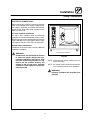
IMPORTANT
FOR YOUR SAFETY
Do not store or use gasoline or other flammable vapors or liquids in the vicinity
of this or any other appliance.
AVERTISSEMENT
Ne pas entreposer ni utiliser de l'essence ni d'autres vapeurs ou liquides inflamĆ
mables dans le voisinage de cet appariel, ni de tout autre appareil.
WARNING: IMPROPER INSTALLATION, ADJUSTMENT, ALTERATION, SERVICE OR
MAINTENANCE CAN CAUSE PROPERTY DAMAGE, INJURY OR DEATH. READ THE
INSTALLATION, OPERATING AND MAINTENANCE INSTRUCTIONS THOROUGHLY
BEFORE INSTALLING OR SERVICING THIS EQUIPMENT
AVERTISSEMENT: UNE INSTALLATION, UN AJUSTEMENT, UNE ALTÉRATION, UN
SERVICE OU UN ENTRETIEN NON CONFORME AUX NORMES PEUT CAUSER DES
DOMMAGES À LA PROPRIÉTE, DES BLESSURES OU LA MORT. LISEZ ATTENTIVEĆ
MENT LES DIRECTIVES D'INSTALLATION, D'OPÉRATION ET D'ENTRETIEN AVANT
DE FAIRE L'INSTALLATION OU L'ENTRETIEN DE CET ÉQUIPEMENT.
The information contained in this manual is important for the proper installation,
use, and maintenance of this oven. Adherence to these procedures and instrucĆ
tions will result in satisfactory baking results and long, trouble free service.
Please read this manual carefully and retain it for future reference.
Les informations données dans le présent manuel sont importantes pour installer,
utiliser et entretenir correctement ce four. Le respect de ces instructions et procéĆ
dures permettra d'obtenir de bons résultats de cuisson et une longue durée de serĆ
vice sans problèmes. Veuillez lire le présent manuel et le conserver pour pouvoir
vous y reporter à l'avenir.
Errors: Descriptive, typographic or pictorial errors are subject to correction. SpecificaĆ
tions are subject to change without notice.
Erreurs:Les erreurs de description, de typographie ou d'illustration font l'objet de
corrections. Les caractéristiques sont sujettes à modifications sans préavis.

Your Service Agency's Address:
Adresse de votre agence de service:
Model/Modèl:
Serial Number/Numéro de série:
Your oven was installed by/
Installateur de votre four:
Your oven's installation was checked by/
Contrôleur de l'installation de votre four:

Table of Contents/Table des Matières
Introduction
The Blodgett CombiĆOven/Steamer 2. . . . .
Description of the CombiĆOven/Steamer 3.
Oven Features 4. . . . . . . . . . . . . . . . . . . . . . .
Installation
Owner's Responsibilities 5. . . . . . . . . . . . . . .
Location 6. . . . . . . . . . . . . . . . . . . . . . . . . . . . .
Agency Approvals 7. . . . . . . . . . . . . . . . . . . .
Utility Connections 8. . . . . . . . . . . . . . . . . . . .
Utility Connections 9. . . . . . . . . . . . . . . . . . . .
Leg Attachment 10. . . . . . . . . . . . . . . . . . . . . .
Stacking 11. . . . . . . . . . . . . . . . . . . . . . . . . . . . .
Adjustments 12. . . . . . . . . . . . . . . . . . . . . . . . .
Final Check Lists 13. . . . . . . . . . . . . . . . . . . . .
Operation
Oven StartĆUp 14. . . . . . . . . . . . . . . . . . . . . . . .
Standard Controls 15. . . . . . . . . . . . . . . . . . . .
Optional Cook & Hold 17. . . . . . . . . . . . . . . . .
Optional Meat Probe 20. . . . . . . . . . . . . . . . . .
Maintenance
Spray Bottle Operating Procedure 21. . . . . .
Cleaning and Preventive Maintenance 22. . .
Decalcification 23. . . . . . . . . . . . . . . . . . . . . . .
Introduction
Le CombiĆfour/étuve à vapeur Blodgett 24. .
Description du CombiĆfour/étuve à vapeur 25
Caractéristiques du four 26. . . . . . . . . . . . . . .
Installation
Responsabilités du propriétaire 27. . . . . . . . .
Placement 28. . . . . . . . . . . . . . . . . . . . . . . . . . .
Normes et Codes 29. . . . . . . . . . . . . . . . . . . . .
Branchement Utilitaires 30. . . . . . . . . . . . . . . .
Branchement Utilitaires 31. . . . . . . . . . . . . . . .
Fixation des pieds 32. . . . . . . . . . . . . . . . . . . .
Superposition Ć Assemblage section
double 33. . . . . . . . . . . . . . . . . . . . . . . . . . . . . .
Vérification finale et derniers réglages 34. . .
Vérifications Finales 35. . . . . . . . . . . . . . . . . . .
Utilisation
Mise en Marche du Four 36. . . . . . . . . . . . . . .
Contrôles Standards 37. . . . . . . . . . . . . . . . . .
Cuisson et Pause en Option 39. . . . . . . . . . .
Sonde à Viande en Option 43. . . . . . . . . . . . .
Entretien
Procédé de fonctionnement de la bouteille
vaporisatrice 44. . . . . . . . . . . . . . . . . . . . . . . . .
Entretien Préventif et Nettoyage 45. . . . . . . .
Détartrage 46. . . . . . . . . . . . . . . . . . . . . . . . . . .

Introduction
2
The Blodgett CombiĆOven/Steamer
For quite some time, commercial cooking equipĆ
ment has remained more or less unchanged.
There are kettles, deck ovens, the good old range
with its legion of pots āand āmany āother āextra
āappliances. The result: time expenditure, excesĆ
sive manual work, and countless cleaning proĆ
cesses. The last āāāfew āāāyears āāhave āāpaved āāthe āāway āāfor
āa revolution in the equipment of restaurant and inĆ
stitutional kitchens.
The Blodgett CombiĆOven/Steamer offers a comĆ
pletely new method of cooking. With the Oven/
Steamer you have the choice of two cooking proĆ
cesses: Steam and Hot Air, either...
D Separately
D Combined, or
D In Sequence
And for easy operation you can choose from three
modes:
Steam Hot Air Combi
Steam &
Hot Air
In the Steam mode you can:
DĂsteam DĂblanch DĂpoach
DĂdefrost DĂrethermalize
In the Hot Air mode you can
DĂroast DĂbake DĂbraise
In the Combi mode you can:
DĂdefrost DĂroast DĂrethermalize
DĂreheat DĂbake DĂsous vide*
DĂproof* DĂcook & hold*
* with optional digital controls
Not āāonly āāthat, āāyou āācan āāuse āātwo āāor āthree functions
in sequence during one cooking process. We call
this:
D combiĆsteaming
D combiĆroasting
D combiĆbaking
The combination of circulating hot air and steam
in the space saving, high performance CombiĆ
Oven/Steamer leads to improvements in the folĆ
lowing areas:
D increased productivity in the kitchen
D a reduction in capital expenditures for multiple
equipment replacement
D a wider range of menu choices
D a simplified cleaning process
The work process is simplified since products are
prepared on or in steam table āpans āand trays.
Food can be cooked, stored, and transported with
āthe āsame āāpans. āSmall āamounts of product can be
processed efficiently; preĆcooked and conveĆ
nience foods can be reheated within minutes.
āMany frozen foods can be processed without preĆ
thawing. This flexibility reduces the need for
kettles and steam tables since there is no need to
keep large amounts of food warm for long periods
of time.
Today the improvement of food quality is more imĆ
portant than ever. Vegetables are cooked in the
Blodgett CombiĆOven/Steamer without water at
the optimal temperature of just under 212_F
(100_C), maintaining valuable vitamins, minerals,
nutrients and trace elements.āāCooking meat in the
Combi results in less shrinkage and a firmer, juicier
product. The Blodgett CombiĆOven/Steamer is
being used more and more for baking. Steam and
Hot āAir āmodes āmake āit āa āgeneral āpurpose baking
appliance.

Introduction
3
Description of the CombiĆOven/Steamer
ABOUT THE OVEN/STEAMER
Blodgett CombiĆOven/Steamers are quality proĆ
duced using highĆgrade stainless steel with first
class workmanship.
The high performance fresh steam generator with
its control system makes it possible to enjoy all of
the advantages of a high quality steamer at the
flick of a switch. Fresh steam enters the oven cavĆ
ity without pressure and is circulated at high
speed. This process enables quick and gentle
cooking and ensures high quality food while proĆ
viding convenient working methods. The steam
generator is completely automatic and protected
from running dry.
A patented quench system keeps the air in the
oven clean. Fumes which arise from roasting and
grilling are extracted from the appliance, quenched,
and directed out through the condenser drain. The
exhaust system is effective in all cooking modes
and results in better quality foods and no flavor
transfer. The fan, which is guarded against acciĆ
dental finger contact, is driven by a quiet and powĆ
erful motor. The condenser draws out excess
steam from the appliance. Condensation and
waste water, which result during steaming and
cleaning, are continuously drained.
The use of high quality insulation impedes excesĆ
sive heat radiation and saves energy.
The Oven/Steamer has optional adjustable legs
which adapt easily to slightly uneven surfaces and
optional floor stands which are designed for use
with all of the table models.
OVEN/STEAMER OPERATION
The practical oven door, with a viewing window,
has a wide swing radius and handle which can be
operated easily, even with wet or greasy hands.
Ease of operation is guaranteed through the simĆ
ple arrangement of the controls. Graphic symbols
make the appliance easy for even inexperienced
kitchen staff to operate. Steam, Hot Air and Combi
modes can be selected with one switch. A fourth
function on the mode selection switch, the Cool
Down mode, allows the oven cavity to cool down
rapidly with the door opened or closed.
Cleaning is kept to a minimum. The interior is
sprayed with a selfĆacting cleaning solution which
interacts with steam to easily remove crusts and
stains. The oven is designed for easy care and is
welded water tight so that the internal cooking
cavity may be rinsed with a hose after the steam
cleaning process.

Introduction
4
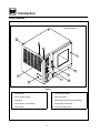
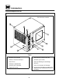
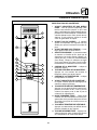
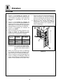
Oven Features
Standard Features
6
5
4
8
7
2
3
9
10
1
Figure 1
1 Control Panel
2 Fuses, Power Supply
3 Oven Door
4 DripĂCollectorĂ(self draining)
5 Door Handle
6 Door Contact Switch
7 VentĂ(not shown)
8 Decalcifying Inlet & Funnel Assembly
9 Decalcifying Valve Lever
10 Tilt Down Panel Screw

Installation
5
Owner's Responsibilities
1. Oven(s) are uncrated, stacked (if applies) and
put in place.
NOTE: Please refer to Leg Attachment and
Stacking Addendum.
2. The owner/operator must have the following
plumbing and electrical requirements met and
installed.
NOTE: Refer to the Utility Connection inforĆ
mation provided.
WARNING!!
Improper installation, adjustment, alterĆ
ation service or maintenance can cause
property damage, injury or death. Read
the installation, operation and mainteĆ
nance instructions thoroughly before
installing or servicing this equipment.
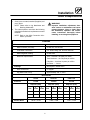
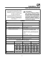
PLUMBING
Water
Water Pressure (min/max) 40 PSI min / 50 PSI max
Cold Water Connection 3/4" Hose Fitting, 3/8" ID hose minimum
Water Regulator Setting 35 PSI static
Mimimum requirements TDS - less than 100 parts per million
Total Hardness - 80Ć120 parts per million
Chlorides - less than 30 parts per million
pH Factor - 7.0Ć8.0
Drainage Atmospheric Vented Drain
Drain Connection 2" Copper
Avg Water Drain Temp. Approximately 122_F / 50_C
ELECTRICAL
COSĆ6 COSĆ101 COSĆ101S
Electrical 9.4 kw 18.5 kw 18.5 kw
Amp/line (max) Amp/line (max) Amp/line (max)
Volt
3
Phase
1
Phase Volt
3
Phase
1
Phase Volt
3
Phase
1
Phase
208 26 46 208 52 89 208 52 89
240 23 40 240 45 77 240 45 77
480 22 N/A 480 22 N/A
Blower Motor .33 HP / .4 kW .5 HP / .5 kW .5 HP / .5 kW

Installation
6
Location
The well planned and proper placement of your
appliance will result in long term operator conveĆ
nience and satisfactory performance.
The following clearances must be maintained beĆ
tween the unit and any combustible or nonĆcomĆ
bustible construction.
D Oven body right side - 1" (2.54 cm)
D Oven body left side - 4" (10 cm)
D Oven body back - 6" (15 cm)
NOTE: For models with hose assemblies on the
back of the unit, the hose must be 1" (2.54
cm) from the wall.
The following clearances are recommended, but
not required, for servicing.
D Oven body sides - 12" (30 cm)
D Oven body back - 12" (30 cm)
Place the unit in an area which is free of drafts and
accessible for proper operation and servicing.
Keep the oven area free and clear of all combusĆ
tibles such as paper, cardboard, and flammable
liquids and solvents.
DO NOT place the oven on a curb base or seal to
the wall; either condition will prevent proper ventiĆ
lation to the blower motors. Slight unevenness can
be corrected with the adjustable legs.
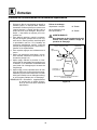
Heat and water sources must not be located near
the air vents on the left side of the unit. Consult the
factory for an optional protective side heat shield
kit if a warm surface or water source is to the left
of the unit.
On all models, tripping the blower motor's thermal
overload device indicates an excessive ambient
temperature on the left side of the unit. This must
be corrected to prevent permanent damage to the
appliance. All motor bearings are permanently luĆ
bricated by the manufacturer; there is no need for
additional lubrication during the operational lifeĆ
time of the motors.

Installation
7
Agency Approvals
THE INSTALLATION INSTRUCTIONS CONĆ
TAINED HEREIN ARE FOR THE USE OF QUALIĆ
FIED INSTALLATION AND SERVICE PERSONNEL
ONLY. INSTALLATION OR SERVICE BY OTHER
THAN QUALIFIED PERSONNEL MAY RESULT IN
DAMAGE TO THE OVEN AND/OR INJURY TO
THE OPERATOR.
Qualified installation personnel are individuals, a
firm, a corporation, or a company which either in
person or through a representative are engaged
in, and are responsible for:
D The installation of electrical wiring from the elecĆ
tric meter, main control box or service outlet to
the electric appliance.
Qualified installation personnel must be experiĆ
enced in such work, be familiar with all precauĆ
tions required and have complied with all requireĆ
ments of state or local authorities having
jurisdiction.
U.S. and Canadian Installations
Reference: National Electrical Code, ANSI/NFPA
70-Latest Edition and/or Canadian Electrical
Code CSA C22.1 as applicable.
This equipment is to be installed in compliance
with the Basic Plumbing Code of the Building OffiĆ
cials and Code Administrators International Inc.
(BOCA) and the Food Service Sanitation Manual of
the Food and Drug Administration (FDA).
Appliance is to be installed with backflow prevenĆ
tion in accordance with applicable federal, provĆ
ince and local codes.
General Export Installations
Installation must conform with Local and National
installation standards. Local installation codes
and/or requirements may vary. If you have any
questions regarding the proper installation and/or
operation of your unit, please contact your local
distributor. If you do not have a local distributor,
please call Blodgett Combi at 0011Ć802Ć860Ć3700.

Installation
8
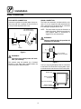
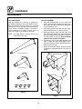
Utility Connections
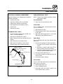
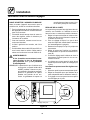
COLD WATER CONNECTION
Connect the appliance to quality water via a presĆ
sure hose with 3/4" couplings. A shut off valve is
to be provided adjacent to the oven.
3/4" Coupling
1/2" appliance hose
with 3/4" hose fittings.
Appliance
Solenoid
Washer
Figure 2
WARNING!!
The use of poor quality water will invaliĆ
date your warranty.
This product must be installed by a licensed
Plumber or Gas Fitter when installed within the
Commonwealth of Massachusetts.
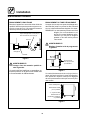
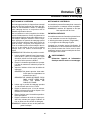
DRAIN CONNECTION
The Drain Vent assembly, included with the unit,
and a 2" (5 cm) copper pipe with standard drain
pitch, must be run to an open drain or connected
to a standpipe equipped with a vent.
NOTE: The waste water can also be directed to a
nearby floor drain. Flexible hose which alĆ
lows trapped water to accumulate in
sagged runs must be avoided.
WARNING!!
Failure to install the drain kit provided will
invalidate your warranty.
2" (5 cm) Drain
(Customer Supplied)
To Drain
Figure 3
A 24" (61 cm) long standpipe must be connected
to the DWV. This allows the escaping water vapor
to exit above the inlet louvers on the back panel.
Breather Vent
Plumber Installed
Connection
Tee, Hose and Clamps
Plumber Installed
Connection To Drain
Figure 4

Installation
9
Utility Connections
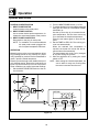
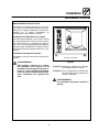
ELECTRICAL CONNECTIONS
Before making any electrical connections to these
units, check that the power supply is adequate for
the voltage, amperage, and phase requirements
stated on the rating name plate mounted on the
right side of the unit.
U.S. and Canadian installations
All ovens, when installed, must be electrically
grounded in accordance with local codes, or in the
absence of local codes, with the National Electrical
Code, ANSI/NFPA 70-Latest Edition and/or CanaĆ
dian National Electric Code C22.2 as applicable.
General export installations
Installation must conform with Local and National
installation standards.
WARNING!!
On 480V units, the fan should be checked
to ensure the proper rotation after conĆ
necting the appliance. See Figure 5. If the
fan turns in the wrong direction, the apĆ
pliance will not function properly and
damage to the unit can occur. Improper
connection of the appliance renders the
warranty invalid.
Direction Of Fan Rotation
Figure 5
NOTE: Disconnect the power supply to the unit
before servicing.
NOTE: All manual resets should be restored beĆ
fore connecting power to the appliance.
WARNING!!
Improper installation will invalidate your
warranty.

Installation
10
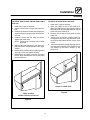
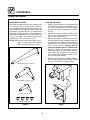
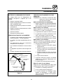
Leg Attachment
LEG VARIATIONS
Legs are available in 4" (101mm), 6" (152mm) āor
ā25" ā(635mm) ālengths āāor āālow profile casters. The 6"
legs are used on the lower section of a double
stacked unit. The 4" legs may be used with the opĆ
tional stands if additional height is required or
when mounting on a counter. The 25" legs are
used for a single oven located on the floor.
NOTE: For safety reasons, casters must not be
used with the 25" legs.
25I Adjustable Leg
4I Leg
6I Adjustable Leg
Low Profile Casters
Figure 6
LEG ATTACHMENT
1. Align the threaded stud on one of the front
legs to the bolt āholeā locatedāāā ināā ātheā āāunit'sā botĆ
tom ācorner. Turn the leg clockwise and tighten
to the nearest full turn.
2. Align the leg plate holes with the bolt holes.
Secure with the two 1/2" bolts provided.
3. Repeat the above steps with the other front
leg. If low profile casters are used, install them
with the locking casters in the front of the oven.
The rear casters do not lock. Ensure that the
locks are set on the front casters.
4. Tip the oven up on the newly installed front
legs. If ācastersā are āused, checkā thatā the locksā
areā setā on ātheā front casters. āRepeat āthe above
steps for the rear legs.
5. Except for units with casters, level the oven by
screwing the adjustable feet in or out as necĆ
essary.
Figure 7

Installation
11
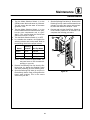
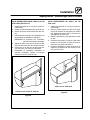
Stacking
TO STACK TWO COSĆ6'S OR ONE COSĆ6 ON A
COSĆ101:
1. Install the 6" legs as directed.
2. Center āa COSĆ6 āunit on top of the lower secĆ
tion.
3. Remove āthe āscrews from the rear āaccess āpanĆ
el āand remove the access panel from the botĆ
tom unit.
4. Carefully āremove āthe āfan āāplug āand disasĆ
semble the steam vent.
NOTE: The fan plug connector can be easily
damaged
5. Alignā theā two rear bolt holes in the lower secĆ
tion with the two threaded holes in the upper
section.
6. Insertā a ābolt from the bottom up through each
of the two holes and tighten securely.
7. Reassemble the steam vent and reconnect
the fan plug. Reinstall the rear access panel
on the lower unit.
COSĆ6 on either
another COSĆ6 or a COSĆ101
Figure 8
TO STACK A COSĆ6 ON A COSĆ101S:
1. Install the 6" legs as directed.
2. Place the COSĆ6 on top of the COSĆ101S.
Make sure that the front and left hand side of
the COSĆ6 line up evenly with the front and left
hand side of the COSĆ101S.
3. Remove the left side access panel from the
lower unit.
4. Threadā oneā ofā theā twoā supplied bolts up
through ātheā COSĆ101S's top ārearāā frame memĆ
ber and into the bottom left rear corner of the
COSĆ6.
5. Thread the second bolt down through the botĆ
tom rear frame member of the COSĆ6 into ātheā
nutā āweldedāā toāā theāā frame member of the
COSĆ101S.
COSĆ6 on a COSĆ101S
Figure 9

Installation
12
Adjustments
BEFORE SWITCHING THE APPLIANCE ON
Before applying power to the unit for the first time,
check for the following conditions:
j All āelectricalā safety provisions have been adĆ
hered to and the electrical connections are
correct.
j Theā ācirculationā āfanā āāturns āāācounterĆclockwise.
Check rotation from inside the oven cavity.
j Water is connected, turned on and all of the
connections are water tight.
j The āāgrease āfilter āand āholder āare āin ātheir proper
positions.
j The āpanā holders on models COSĆ6 and
COSĆ101 are āinserted āinto the oven cavity.
Stationary rack guides are provided with the
COSĆ101S.
WARNING!!
If the fan turns in the wrong direction, the
appliance will not function properly and
can be damaged.
NOTE: When the unit is turned on, or after it has
been OFF for 5 hours and then turned on,
āthe steam generator āautomatically flushes
for 75 seconds. The steam generator then
fills to the proper water level. The unit is
now ready for operation.
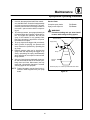
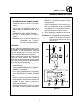
DOOR ADJUSTMENT
The door latch may be adjusted in two directions,
in and out, and up and down, using the following
procedure:
1. Adjust up and down by loosening the two
boltsā holdingā theā latch to the face of the unit
(A).
2. Make āadjustmentsā soā thatā theā leadingā face of
the latch is centered in the opening of the hanĆ
dle assembly.
3. Tighten the bolts so that there is no further
movement.
4. Adjust in and out by loosening the bolt on top
of the latch (B).
5. The āāadjustment āāface āāis āstepped āso āthat moveĆ
ment is limited with the bolt tightened properĆ
ly.
6. The āadjustment āis ācorrect āwhen āthe ādoor
closes firmly and no steam leaks from the gasĆ
ket.
The hinges can also be adjusted as follows:
1. Be certain the latch is adjusted properly.
2. Adjustā hinges āso āthatā the door back and the
unit face are parallel (C).
3. The adjustment is correct when no steam
leaks through the gasket.
A
B
C
Oven
Door
Figure 10

Installation
13
Final Check Lists
ELECTRICAL CONTROL COMPARTMENT
Applied voltage to unit voltage/phase suitable for
appliance specified.
j Remove side panel
j Set motor protector (F2) to on position
j Adjust motor protector to maximum
j Reset high limit thermostats F3 and F6
j Check fuses
j Reinstall side panel
PLUMBING FINAL CHECK
j Incoming water pressure within 40 PSI (miniĆ
mum) - 50 PSI (maximum)
j Atmospheric vented drain in place
j Water solenoid properly bracketed and not
leaking
j Water feed lines intact without leaks
j Water pressure regulator is set to 35 psi
j Optional spray hose connected properly
Washer
Fill
Solenoid
Hose and Spray
Washer
Regulator Assembly
Y" Fitting
Cold water supply
Spray Hose Connection
Figure 11
OVEN OPERATIONAL TESTS
NOTE: Checks to be made by customer or authoĆ
rized service agent.
Cool Down Mode
j Verify oven fan runs with door open
Combi Mode
Turn to COMBI mode, set thermostat to 350_F
(177_C) and verify:
j Boiler flushes and fills
j Boiler preheats to 185_F (85_C) then switches
to HOT AIR
j When HOT AIR reaches 350_F (177_C) HOT
AIR shuts off and STEAM comes on
Steam Mode
Turn on STEAM mode and verify (Control Panel
Removed):
j Check timer operation in all three positions
1. Set timer to OFF position, buzzer should
sound
2. Set timer in position other than OFF or
STAY ON, timer should count down
3. Set timer in STAY ON position, oven should
operate continuously without timer
j Run light (power light) turns on
j Unit produces steam, window fogs, door seal
does not leak
j Quenching system working
Hot Air Mode
Turn to HOT AIR mode and set thermostat to
400_F (205_C) and verify:
j Heat demand light is on
j Oven is heating properly
j Heat lights shuts off at 400_F (205_C) and
oven maintains 400_F (205_C)

Operation
14
Oven StartĆUp
STEAM MODE (if applicable)
1. Turn the mode selector switch to STEAM.
2. The green POWER Indicator lamp on the front
control panel lights.
3. The steam generator flushes and drain autoĆ
matically for 75 seconds if the unit has been off
for at least 5 hours.
4. The steam generator begins to fill. After two
minutes, the FILL indicator lamp on the front
control panel blinks. The convection blower
and POWER lamp turn off.
5. When the steam generator is filled to the propĆ
er level, the convection blower, interior lights
and POWER indicator lamp turn on.
6. Steam fills the cavity and is controlled by a
nonĆaccessible internal thermostat.
HOT AIR MODE (if applicable)
1. Turn the mode selector switch to Hot Air.
2. The green POWER Indicator lamp on the front
control panel lights.
3. Set the hot air thermostat to the desired temĆ
perature.
4. The thermostat lamp lights, indicating the cavĆ
ity temperature is below the desired set point.
5. When the cavity temperature reaches the deĆ
sired set point, the temperature indicator lamp
goes off. The convection blower shuts off.
COMBI MODE (if applicable)
1. Turn the mode selector switch to COMBI.
2. The green POWER indicator lamp on the front
control panel lights.
3. Set the Hot Air thermostat to the desired temĆ
perature.
4. The steam generator flushes and drain autoĆ
matically for 75 seconds if the unit has been off
for at least 5 hours.
5. The steam generator begins to fill. After two
minutes the FILL indicator lamp on the front
control panel blinks. The convection blower
and POWER lamp do not shut down.
6. When the steam generator comes up to a preĆ
determined temperature, the hot air thermoĆ
stat lamp illuminates, indicating the cavity
temperature is below the desired set point.
7. When the cavity temperature reaches the deĆ
sired set point, the temperature indicator lamp
goes off.
8. The steam and hot air burners toggle back
and forth responding to the thermostat set
points.

Operation
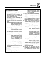
15
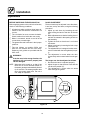
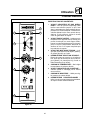
Standard Controls
4
6
5
1
3
7
8
2
Figure 12
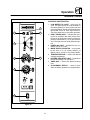
CONTROLS IDENTIFICATION
1. LOW WATER FILL LIGHT - during the fill
cycle, this light remains on until the water in
the steam generator is at the proper level and
up to temperature. During normal operation the
light should not be on. If the light comes on,
check the water level in the steam generator.
2. DON'T STEAM LIGHT - indicates the unit is
too hot to operate in the steam mode. Place
the unit in the Cool Down mode until the temĆ
perature is below 230_F (110_C) and open the
door. This light does not inhibit steam producĆ
tion.
3. POWER ON LIGHT - indicates the unit is in
Steam, Hot Air or Combi.
4. MODE SELECTOR SWITCH - turns power
to the oven on or off. Allows selection of
Steam, Hot Air, Combi or Cool Down Modes.
5. TEMPERATURE DIAL - used to set desired
cooking temperature.
6. HEATING INDICATOR LIGHT - lights when
the Hot Air heating is in operation.
7. TIMER DIAL - used to set desired cooking
time.
8. FLUSH/DRAIN SWITCH - used to flush/
drain the steam generator for decalcification.

Operation
16
Standard Controls
OPERATION
1. Turn the MODE SELECTOR Switch (4) to the
desired function.
The POWER ON Light (3) illuminates.
2. Set the TIMER (7) for the desired cooking time
or set it to STAY ON. The buzzer sounds and
the unit shuts off when the time has expired.
3. For the HOT AIR and COMBI modes, set the
TEMPERATURE Dial (5) to the desired cook
temperature. The HEATING INDICATOR Light
(6) illuminates and stays lit until the desired
temperature is reached. The temperature dial
does not operate during the STEAM portion of
the COMBI mode.
4. The selected mode operates automatically.
The temperature, time and mode can be alĆ
tered at any time during the cooking process.
The operation can be stopped by the use of
the Mode Selector Switch or by opening the
door.
5. At the end of the specified time period, the
buzzer sounds and the appliance shuts off auĆ
tomatically. Move the TIMER (7) to the STAY
ON position to stop the buzzer and restart the
unit.
6. To cool down the oven cavity, switch the
MODE SELECTOR Switch (4) to COOL
DOWN. In the Cool Down mode neither the
temperature dial or the timer will be operationĆ
al. The blower will function with the door open
or closed.
7. The mode selector switch is also the main
power switch. In the OFF position the apĆ
pliance is not operational.
La page est en cours de chargement...
La page est en cours de chargement...
La page est en cours de chargement...
La page est en cours de chargement...
La page est en cours de chargement...
La page est en cours de chargement...
La page est en cours de chargement...
La page est en cours de chargement...
La page est en cours de chargement...
La page est en cours de chargement...
La page est en cours de chargement...
La page est en cours de chargement...
La page est en cours de chargement...
La page est en cours de chargement...
La page est en cours de chargement...
La page est en cours de chargement...
La page est en cours de chargement...
La page est en cours de chargement...
La page est en cours de chargement...
La page est en cours de chargement...
La page est en cours de chargement...
La page est en cours de chargement...
La page est en cours de chargement...
La page est en cours de chargement...
La page est en cours de chargement...
La page est en cours de chargement...
La page est en cours de chargement...
La page est en cours de chargement...
La page est en cours de chargement...
La page est en cours de chargement...
La page est en cours de chargement...
-
 1
1
-
 2
2
-
 3
3
-
 4
4
-
 5
5
-
 6
6
-
 7
7
-
 8
8
-
 9
9
-
 10
10
-
 11
11
-
 12
12
-
 13
13
-
 14
14
-
 15
15
-
 16
16
-
 17
17
-
 18
18
-
 19
19
-
 20
20
-
 21
21
-
 22
22
-
 23
23
-
 24
24
-
 25
25
-
 26
26
-
 27
27
-
 28
28
-
 29
29
-
 30
30
-
 31
31
-
 32
32
-
 33
33
-
 34
34
-
 35
35
-
 36
36
-
 37
37
-
 38
38
-
 39
39
-
 40
40
-
 41
41
-
 42
42
-
 43
43
-
 44
44
-
 45
45
-
 46
46
-
 47
47
-
 48
48
-
 49
49
-
 50
50
-
 51
51


Blodgett COS-6 Mode d'emploi
- Taper
- Mode d'emploi
dans d''autres langues
Documents connexes
-
Blodgett BCM-102 Mode d'emploi
-
-
Blodgett COS6 spécification
-
Blodgett B14G spécification
-
-
-
Blodgett BCX -14G Mode d'emploi
-
-
-