Genius SPIN4 Articulated Beam Kit Mode d'emploi
- Taper
- Mode d'emploi
La page est en cours de chargement...
La page est en cours de chargement...

1
ITALIANO
Il kit articolazione è stato studiato per permettere la trasformazio-
ne delle sbarre rigide in sbarre articolate, con altezza massima di
accesso pari a 3 metri.
Il kit articolazione può essere applicato esclusivamente alle
sbarre per SPIN 4.
Per il montaggio seguire attentamente le istruzioni:
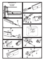
Calcolare la lunghezza delle due parti, A e B, secondo lo
schema di Fig. 1.
Togliere i due tappi rossi alle due estremità dell’asta e sfilare il
profilo in gomma.
Tagliare la sbarra ed il profilo in gomma secondo le lunghezze
calcolate.
Per il corretto funzionamento della sbarra è necessario
tagliare i due profili in gomma almeno 15mm più corti del
relativo spezzone di sbarra.
Inserire la dima n° 3 (Rif. C Fig. 2) nello spezzone A come indicato
in Fig. 2. Tracciare e forare con una punta ø5.5.
Inserire il particolare D ed avvitare le due viti F con le rispettive
rondelle E come indicato in Fig. 3.
Infilare il particolare I e fissarlo tramite il perno G ed il seeger
H come in Fig.4.
Posizionare sullo spezzone B la dima di foratura L, come in Fig.
5. Tracciare e forare con una punta di ø8.
1.
2.
3.
4.
5.
6.
7.
Inserire il particolare M nello spezzone appena forato, Fig. 6.
Inserire lo spezzone B nel particolare I, inserire nei rispettivi fori i
tiranti N e bloccarli utilizzando le rondelle O ed i dadi P come
in Fig. 7.
Rimontare i profili in gomma ed i tappi rossi sui rispettivi spez-
zoni.
In base all’apertura della sbarra posizionare la dima Q sul co-
fano Fig. 8. Tracciare e forare con una punta ø5.5.
Posizionare il particolare R e fissarlo con le viti S, Fig. 9. Per il
bloccaggio del particolare R posizionare, all’interno del cofano
i dadi e la rondelle da M5 fornite nel Kit.
Montare la sbarra al cofano come illustrato nel manuale d’in-
stallazione della barriera.
Fissare la fune metallica T al particolare U, Fig. 10, per mezzo
dell’occhiello V e del morsetto Z.
Per assicurare un corretto fissaggio del morsetto si consiglia
di rimuovere, nella zona di fissaggio, la plastica attorno alla
fune metallica.
Allineare i due spezzoni di sbarra A e B agendo sul dado W,
Fig. 10.
8.
9.
10.
11.
12.
13.
14.
15.
ENGLISH
The articulation kit was designed to convert rigid beams into arti-
culated beams, with maximum access height of 3 metres.
The articulation kit can be fitted only on beams for SPIN 4.
To install, carefully follow the instructions below:
Calculate the length of the two parts, A and B, according to
the diagram in Fig. 1.
Remove the two red plugs on the two ends of the rod and
withdraw the rubber profile.
Cut the beam and rubber profile according to the calculated
lengths.
To ensure the beam operates correctly, cut the two rubber
profiles at least 15 mm shorter than the relevant beam
section.
Insert template No. 3 (Ref. C Fig. 2) in section A as shown in Fig.
2. Mark and drill through with a ø5.5 bit.
Insert part D and screw the two screws F with their washers E
as shown in Fig. 3.
Fit part I and secure it with pin G and Seeger ring H as shown
in Fig. 4.
Locate the drilling template L on section B as shown in Fig. 5.
Mark and drill through with a ø8 bit.
Insert part M on the section you have just drilled, Fig. 6.
Insert section B on part I, insert tie-rods N in their holes and secure
1.
2.
3.
4.
5.
6.
7.
8.
9.
them with washers O and nuts P as shown in Fig. 7.
Re-fit the rubber profiles and the red plugs on the relevant
sections.
According to the beam opening, locate template Q on the
housing, Fig. 8. Mark and drill through with a ø5.5 bit.
Position part R and secure it with screws S, Fig. 9. To secure part
R, locate the nuts and M5 washer (supplied with the kit) inside
the housing.
Fit the beam to the housing as shown in the barrier installation
manual.
Fix the wire rope T to part U, Fig. 10, using eyelet V and clip Z.
To ensure the clamp is correctly secured, we advise you to
remove, in the securing zone, the plastic around the metal
rope.
Align the two beam sections A and B, using nut W, Fig.10.
10.
11.
12.
13.
14.
15.
FRANÇAIS
Le kit articulation a été étudié pour permettre la transformation
des lisses rigides en lisses articulées, avec une hauteur maximale
d’accès égale à 3 mètres.
Le kit articulation peut être exclusivement appliqué aux lisses
pour SPIN 4.
Pour le montage, suivre attentivement les instructions:
Calculer la longueur des deux parties, A et B, d’après le sché-
ma de la Fig. 1.
Enlever les deux bouchons rouges aux deux extrémités de la
lisse et retirer le profil en caoutchouc.
Couper la lisse et le profil en caoutchouc suivant les longueurs
calculées.
Pour le fonctionnement correct de la lisse, couper les deux
profils en caoutchouc d’au moins 15mm plus courts que le
tronçon de lisse correspondant.
Introduire le gabarit n° 3 (Réf. C Fig. 2) dans le tronçon A d’après
la Fig. 2. Tracer et percer avec un foret ø5,5.
Introduire la pièce D et visser les deux vis F avec les rondelles
correspondantes E et d’après la Fig. 3.
Enfiler la pièce I et la fixer par l’intermédiaire de l’axe G et
l’anneau de retenue H d’après la Fig. 4.
Positionner sur le tronçon B le gabarit de perçage L, d’après la
Fig. 5. Traccer et percer avec un foret de ø8.
1.
2.
3.
4.
5.
6.
7.
Introduire la pièce M dans le tronçon qu’on vient de percer,
Fig. 6.
Introduire le tronçon B dans la pièce I, introduire dans les trous
correspondants les tirants N et les bloquer en utilisant les ron-
delles O ainsi que les écrous P d’après la Fig. 7.
Remonter les profils en caoutchouc et les bouchons rouges sur
les tronçons correspondants.
Suivant l’ouverture de la lisse, positionner le gabarit Q sur le
coffret Fig. 8. Tracer et percer avec un foret ø5,5.
Positionner la pièce R et la fixer avec les vis S, Fig. 9. Pour le
blocage de la pièce R positionner, à l’intérieur du coffret les
écrous et la rondelle de M5 fournie dans le Kit.
Monter la lisse sur le coffret comme l’illustre le manuel d’instal-
lation de la barrière.
Fixer le câble d’acier T sur la pièce U, Fig. 10, au moyen de
l’œillet V et de l’étau Z.
Pour assurer une fixation correcte de la borne, on conseille
d’enlever, dans la zone de fixation, le plastique autour du
câble métallique.
Aligner les deux tronçons de lisse A et B en agissant sur l’écrou
W, Fig.10.
8.
9.
10.
11.
12.
13.
14.
15.
La page est en cours de chargement...
-
 1
1
-
 2
2
-
 3
3
-
 4
4


Genius SPIN4 Articulated Beam Kit Mode d'emploi
- Taper
- Mode d'emploi
dans d''autres langues
Documents connexes
-
Genius Articulation Kit Assembly Instructions
-
-
-
-
-
-
Genius RAINBOW 324 524 724 C Mode d'emploi
-
-
-