
OWNER’S MANUAL OM-274912A
2016−04
For SubArc Hinge Mounting Bracket (301136)
1. Safety Symbol Definitions
DANGER! − Indicates a hazardous situation which, if not
avoided, will result in death or serious injury. The possible
hazards are shown in the adjoining symbols or explained in
the text.
DANGER ! - Indique une situation dangereuse qui, si elle
n’est pas évitée, entraînera la mort ou des blessures graves.
Les éventuels risques sont représentés par les symboles
joints ou expliqués dans le texte.
Fsafe1 2013-10
Beware of electric shock from wiring. Disconnect input pow-
er before installing this kit. Reinstall all panels and covers.
Attention aux décharges électriques au contact des câbles.
Couper l’alimentation électrique avant d’installer ce kit. Ré-
installer tous les panneaux et couvercles.
Fsafe7 2013-10
Indicates a hazardous situation which, if not avoided, could
result in death or serious injury. The possible hazards are
shown in the adjoining symbols or explained in the text.
Indique une situation dangereuse qui, si elle n’est pas évitée,
entraînera la mort ou des blessures graves. Les éventuels
risques sont représentés par les symboles joints ou exp-
liqués dans le texte.
Fsafe2 2013-10
Wear safety glasses with side shields.
Porter des lunettes de sécurité avec écrans latéraux.
Fsafe8 2013-10
NOTICE
Indicates statements not related to personal injury.
Signale des consignes non associées aux dommages cor-
porels.
Indicates special instructions.
Fournit des instructions spéciales.
Fsafe3 2013-10
Have only trained and qualified persons install, operate, or
service this unit. Read the safety information at the begin-
ning of these instructions and in each section. Call your dis-
tributor if you do not understand the directions. For WELD-
ING SAFETY and EMF information, read owner’s manual(s).
Ne confiez l’installation, l’exploitation ou l’entretien de cet
appareil qu’à des personnes compétentes et qualifiées. Lire
les directives de sécurité au début de ces instructions et
dans chaque section. Appeler votre distributeur si vous
ne comprenez pas les directives. Lire le(s) manuel(s)
d’utilisateur pour des renseignements sur la SÉCURITÉ
DE SOUDAGE et les champs électromagnétiques.
Fsafe15 2013-10
CALIFORNIA PROPOSITION 65 WARNINGS
Welding or cutting equipment produces fumes or gases which contain chemicals known to the State of California to cause birth defects and, in some
cases, cancer. (California Health & Safety Code Section 25249.5 et seq.) This product contains chemicals, including lead, known to the state of Cali-
fornia to cause cancer, birth defects, or other reproductive harm. Wash hands after use.
Les équipements de soudage et de coupage produisent des fumées et des gaz qui contiennent des produits chimiques dont l’État de Californie recon-
naît qu’ils provoquent des malformations congénitales et, dans certains cas, des cancers. (Code de santé et de sécurité de Californie, chapitre
25249.5 et suivants) Ce produit contient des produits chimiques, notamment du plomb, dont l’État de Californie reconnaît qu’ils provoquent des
cancers, des malformations congénitales ou d’autres problèmes de procréation. Se laver les mains après utilisation.
Fsafe4 2013-10
2. Description
The mounting hinge bracket is designed to provide support for Miller®SubArc welding equipment or other welding equipment. This unit is intended to be
mounted on a fixed arm.
Contact the manufacturer of the fixed arm to ensure it is capable of supporting the weight of the mounting hinged bracket and attached
equipment.
3. Specifications
Product Type Overall Dimensions Weight
Mounting Hinge Bracket 16 in. in. X 10.125 in. X 10 in.
(406 mm x 257 mm x 254 mm)
66 lbs
(30 kg)
4. Tools Needed
3/8 in.
7/16, 9/16 in.

OM-274912 Page 2
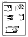
5. Dimensions
16.000 in.
(406 mm)
Top View
275 557-A
90° Position
10.000 in.
(254 mm)
Front View
90° Position
Back View
90° Position
10.125 in.
(257 mm)
15.000 in.
(381 mm)
7.125 in.
(181 mm)
Top View
180° Position

OM-274912 Page 3
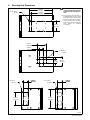
6. Mounting Hole Dimensions
275 558-A
! Turn Off power for boom and
column and all other electrical
equipment before working on
unit.
. The mounting hinge bracket is
provided with 1/2-13 x 2 in. socket
head cap screws for attaching the
bracket to a fixed arm or movable
slide. If desired, M12 x 51 hard-
ware may be used. In this case the
holes should be threaded
accordingly.
5.000 in.
(127 mm)
10.000 in.
(254 mm)
10.750 in.
(273 mm)
6 x ∅ .313 in.
(8 mm )
8 x ∅ .313 in.
(8 mm )
4.331 in.
(110 mm)
1.969 in.
(50 mm)
4.331 in.
(110 mm)
1.969 in.
(50 mm)
4 x ∅ .531 in.
(13 mm )
4 x ∅ .531 in.
(13 mm )
6.000 in.
(152 mm)
2.500 in.
(64 mm)
2.500 in.
(64 mm)
2.500 in.
(64 mm)
2.500 in.
(64 mm)
8.500 in.
(216 mm)

OM-274912 Page 4
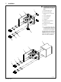
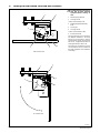
7. Installation
! Turn Off power for boom and
column and all other electrical
equipment before working on
unit.
1 Mounting Hinge Bracket
90° Position recommended.
2 1/2 - 13 x 2.00 in. Soc HD Cap
Screws
3 1/2 in. Lock Washers
4 1/2 in. Flat Washers
5 1/2 in. Hex Nuts
6 Locking Pin
Can be placed on top or bottom.
7 Knurled Set Screw
Can be placed on top or bottom.
8 Fixed Arm
. It is recommended that before
mounting the hinge bracket, be
sure the locking pin is in place, and
the knurled set screw is tightened.
The hinge bracket can be mounted to
a fixed arm using a 3/8 in. Allen wrench
to tighten the four 1/2 - 13 x 2.00 in.
screws and hardware. Torque hard-
ware to 75±2 ft. lbs. (102±3 N⋅M).
275 595-A
1
7
5
2
3
4
6
2
3
4
1
7
8

OM-274912 Page 5
8. Locking Pin And Knurled Set Screw Hole Locations
! Turn Off power for boom and col-
umn and all other electrica
l
equipment before working on
unit.
1 Mounting Hinge Bracket
2 Locking Pin Hole
Used to mount bracket at 90°.
3 Welding Equipment Mounting
Plate
4 Locking Pin
5 Locking Pin Hole
Used to mount bracket at 180°.
6 Knurled Set Screw
The hinge bracket can be mounted in
two different orientations. The hinge
bracket can be mounted so that the
mounting plate swings left hand from
180° to 90°, or flipped upside down to
swing right hand from 180° to 90°.
The locking pin and knurled set screw
can be placed on the top or bottom o
f
the hinge regardless of the orientation
of the hinge.
275 596-A
12
3
45
6
1
2
3
4
5
6
180° Position View
90° Position View

OM-274912 Page 6
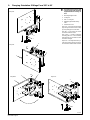
9. Changing Orientation Of Hinge From 1805 to 905
! Turn Off power for boom and
column and all other electrical
equipment before working on
unit.
1 Mounting Hinge Bracket
2 Locking Pin
3 Hole − Locking Pin
4 Welding Equipment Mounting
Plate
5 Knurled Set Screw
Step One − Unlock the hinge bracket
by pressing the button on the locking
pin, and pulling pin out of the hole.
Step two − Turn knurled set screw
counterclockwise to loosen.
Step Three − Position equipment
mounting plate 90° to the mounting
hinge bracket. Turn knurled set screw
clockwise until tight.
Step Four − Lock hinge bracket in po-
sition by inserting locking pin into the
same hole from which it was removed.
275 628-A
Step One
Step Two
Step Three Step Four
1
2
5
3
1
4
5
4
1
1
2
3

OM-274912 Page 7
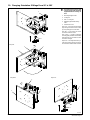
10. Changing Orientation Of Hinge From 905 to 1805
! Turn Off power for boom and
column and all other electrical
equipment before working on
unit.
1 Mounting Hinge Bracket
2 Locking Pin
3 Hole − Locking Pin
4 Welding Equipment Mounting
Plate
5 Knurled Set Screw
Step One − Unlock the hinge bracket
by pressing the button on the locking
pin, and pulling pin out of the hole.
Step two − Turn knurled set screw
counterclockwise to loosen.
Step Three − Position equipment
mounting plate parallel to the mounting
hinge bracket. Turn knurled set screw
clockwise until tight.
Step Four − Lock hinge bracket in po-
sition by inserting locking pin into the
same hole from which it was removed.
275 597-A
Step One
Step Two
Step Three Step Four
5
4
1
1
2
3
1
2
5
3
1
4

OM-274912 Page 8
11. Replacement Parts List
DescriptionPart No.
Item
No.
Quantity
1 275435 Pin, Quick Release T-Handle 1.................. ...... ................................
2 275438 Knob, Cast Iron Knurled Rim 1.................. ...... .................................
Use only Manufacturer’s Suggested Replacement Parts. Model number required when ordering parts.
Notes
-
 1
1
-
 2
2
-
 3
3
-
 4
4
-
 5
5
-
 6
6
-
 7
7
-
 8
8


Miller SUBARC HINGE MOUNTING BRACKET (301136) Le manuel du propriétaire
- Taper
- Le manuel du propriétaire
- Ce manuel convient également à
dans d''autres langues
Documents connexes
-
Miller INTELLX WIRE DRIVE ASSEMBLIES Le manuel du propriétaire
-
-
Miller MF170157G Le manuel du propriétaire
-
-
-
-
-
-
-